
Related Manuals for BEKA A504G-SS-PM


Summary of Contents for BEKA A504G-SS-PM
- Page 1 BA504G-SS-PM and BA524G-SS-PM general purpose loop-powered panel mounting indicators Issue 1 Issue: 1 11th September 2018...
-
Page 2: Table Of Contents
CONTENTS Description Maintenance Fault finding during commissioning Operation Fault finding after commissioning Controls Servicing Routine maintenance Applications Guarantee Transmitter loops Customer comments Remote indication Accessories Installation Units of measurement and instrument Location identification. Installation procedure Display backlight Units of measurement and tag marking 8.2.1 Loop powering the backlight on scale card. -
Page 3: Description
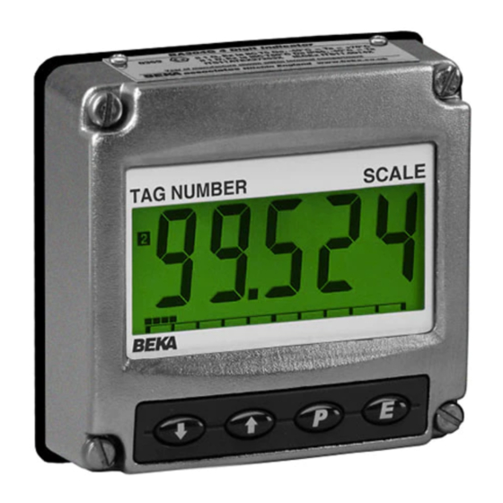
DESCRIPTION OPERATION These rugged panel mounting, general purpose Fig 1 shows a simplified block diagram of all digital indicators display the current flowing in a models. The 4/20mA input current flows through 4/20mA loop in engineering units. They are loop resistor R1 and forward biased diode D1. -
Page 4: Controls
Controls APPLICATIONS Both models are controlled and calibrated via four front panel push buttons. In the display mode i.e. Transmitter loops when the indicator is displaying a process variable, Both models may be connected in series with these push buttons have the following functions: almost any 4/20mA current loop and calibrated to display the measured variable or control signal in While this button is pushed the... -
Page 5: Installation
Fig 3 Indicator providing a remote display Fig 4 Recommended panel cut-out dimensions INSTALLATION 4.1 Location BA504G-SS-PM and BA524G-SS-PM indicators have a 316 stainless steel enclosure. Both have IP66 front of panel ingress protection after a 7J impact and have a thick armoured window which will withstand a 4J impact. -
Page 6: Emc
Custom printed scale cards are available from BEKA associates as an accessory. To remove the scale card from an indicator carefully pull the transparent tab at the rear of the... -
Page 7: Summary Of Configuration Functions
CONFIGURATION AND CALIBRATION Summary of configuration functions Both indicators are configured and calibrated via This section summarises each of the main four front panel push buttons. The configuration configuration functions and includes a cross functions are contained in an easy to use intuitive reference to a more detailed description. - Page 8 Display Summary of function Function of ( push button C--P The indicator may be configured to display the input current in milliamps, or the input current as a percentage of the 4/20mA input when the ( push button is operated in the display mode. See section 5.8 Tare function tArE...
-
Page 10: Indicator Function: Func
Indicator function: FunC Position of the decimal point: dP This configuration function defines the relationship A dummy decimal point can be positioned between between the indicator’s 4/20mA input current and any of the digits or it may be absent. To position the indicator’s display. -
Page 11: Calibration Using Internal References: 5Et
The indicator’s digital display at which the Calibration using internal reference: 5Et Using the 5Et function the indicator can be bargraph starts is defined by the bArLo sub- calibrated without the need to know the value of function which is selected by pressing the * the 4/20mA input current, or to disconnect the button followed by the ( button which will reveal indicator from the 4/20mA loop. -
Page 12: Security Code: Code
CodE prompt in the configuration menu. The appropriate end of the bargraph. revised security code will be activated when the indicator is returned to the display mode. Please contact BEKA associates sales department if the security code is lost. 5.11 Reset to factory defaults: r5Et... -
Page 13: Lineariser Calibration Using An External Current Source
LINEARISER Lineariser calibration using an external A sixteen segment, seventeen break-point (0 to 16) current source. lineariser may be selected in the FunC section of This method allows direct calibration of the the configuration menu. The position of each lineariser with an external current source and is the preferred method when traceability is required. -
Page 15: Example, Adding Break-Points
The delete break-point sub-function dEL operates required, using the * button select the new in exactly the same way as the Add sub-function highest break-point 2 : 2 and add the second described above. Once within the dEL sub- additional break-point by operating the ( push function each time the ( button is pressed a button which will result in a display of 2 : 3. -
Page 16: Example, Adding Break-Points To A New Indicator
To add a break-point using the & or * button Press ( and use the & or * button and the ( select 5Et from the configuration menu and press button to move between digits, to enter the required indicator display at the first break-point. ( which will result in the Add sub-function prompt being displayed. -
Page 17: Maintenance
Indicators which fail within the guarantee period No display Incorrect Check supply should be returned to BEKA associates or our local 0V between wiring or no voltage and voltage agent. It is helpful if a brief description of the fault terminals 1 &... -
Page 18: Accessories
ACCESSORIES 8.2.1 Loop powering the backlight Units of measurement & instrument The backlight is loop powered by connecting it in identification. series with the indicator’s 4/20mA input as shown New indicators are supplied with a printed scale in Fig 12, which increases the maximum indicator card showing the units of measurement and tag voltage drop from 1.2 to 5V. -
Page 19: Separately Powering The
8.2.2 Separately powering the backlight Alarms The optional backlight may also be powered from a Both models can be supplied with factory fitted separate power supply as shown in Fig 13. dual solid state, single pole, voltage free alarm outputs. Each alarm output may be independently configured as a high or low alarm with a normally open or normally closed output in the non-alarm condition. -
Page 20: Solid State Output
8.3.1 Solid state output Each alarm has a galvanically isolated single pole solid state switch output which is shown in Fig 15. The output is polarised and current will only flow in one direction. less than 5Ω + 0.7V Roff greater than 1MΩ... -
Page 22: Configuration And Adjustment
8.3.2 Configuration and adjustment Summary of alarm configuration functions When optional alarms are fitted to a loop powered indicator the configuration menu is extended as Display Summary of function shown in Fig 17. The additional functions appear between the 5Et and the C--P functions for the Alarm enable EnbL BA504G-SS-PM and between bAr and C--P for the... -
Page 23: Alarm Enable: Enbl
8.3.3 Alarm enable: EnbL This function allows each alarm to be enabled or To check or change the alarm output status, select disabled without altering any of the alarm no . nC from the alarm configuration menu and press parameters. To enable or disable the alarm select ( to reveal the setting. -
Page 24: Alarm Silence Time: 5Il
8.3.9 Alarm silence time: 5iL This function is primarily intended for use in small This direct setpoint access menu is enabled and installations where the alarm output directly the separate security code entered from the AC5P operates an alarm annunciator such as a sounder function in the alarm configuration menu as shown or beacon. -
Page 25: Ba524G-Ss-Pm Bargraph
8.3.13 Displaying setpoints on a BA524G-SS-PM bargraph. One of the selectable bargraph formats Alr5P allows a low or a high setpoint plus the displayed value to be represented, or a low and a high setpoint plus the displayed value to be represented by the bargraph as shown in Fig 19.
Need help?
Do you have a question about the A504G-SS-PM and is the answer not in the manual?
Questions and answers