
Related Manuals for BEKA BA507E-SS


Summary of Contents for BEKA BA507E-SS
- Page 1 BA507E-SS & BA527E-SS Rugged general purpose loop-powered panel mounting indicators Issue 2 Issue: 2 May 2017...
-
Page 2: Table Of Contents
8.3.12 Adjusting alarm setpoints from the display mode. 8.3.13 Displaying setpoints on bargraph. 8.4 Display backlight 8.4.1 Loop powering the backlight 8.4.2 Separately powering the backlight. The BA507E-SS & BA527E-SS are CE marked to show compliance with the European EMC Directive 2004/108/EC... -
Page 3: Description
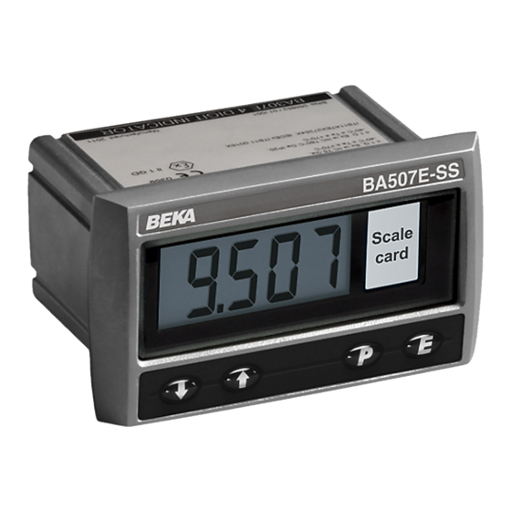
Model Display Each time a 4/20mA current is applied to the instrument, initialisation is performed during which BA507E-SS 4 digits 15mm high all segments of the display are activated, after five seconds the instrument displays the input current BA527E-SS... -
Page 4: Controls
Fig 3 shows points may not be 4 and 20mA. a typical application in which the 4/20mA output from a gas analyser is connected to a BA507E-SS loop powered indicator to provide a remote indication of the analyser’s output. Again it is... -
Page 5: Installation
Although the front of the indicators have IP66 protection, they should be shielded from continuous direct sunlight and severe weather conditions. The BA507E-SS and BA527E-SS may be located in any panel providing that the operating temperature is between –40°C and +70°C. -
Page 6: Indicator Earthing
A pack of self-adhesive scale cards printed with common units of measurement is available as an 4.3 Indicator earthing accessory from BEKA associates. Custom printed Both indicators have an M4 earth stud on the rear panel which should be electrically connected to the scale cards can also be supplied. - Page 7 Align the self-adhesive printed scale card onto the flexible strip and insert the strip into the indicator as shown below. Fig 7 Inserting flexible strip carrying scale card into slot at the rear of indicator.
-
Page 8: Configuration And Calibration
If calibration is not requested, indicators will be configured as follows: 'SEt' Calibration of display using internal references. BA507E-SS BA527E-SS Enables the zero and span of the Access code ‘CodE’ 0000 0000 indicator to be adjusted without the Function ‘FunC’... - Page 10 Display Summary of function 5.2 Indicator function: ‘FunC’ This configuration function defines the relationship 'C - - P' Function of P push-button between the indicator’s 4/20mA input current and The indicator may be configured to display the indicator’s display. Three alternatives are the input current in milliamps, or the input available: current as a percentage of the 4/20mA...
-
Page 11: Calibration Using An External
5.4 Position of the decimal point: ‘dP’ 5.6 Calibration using internal reference: ‘SEt’ A dummy decimal point can be positioned between Using the ‘SEt’ function the indicator can be any of the digits or it may be absent. To position the calibrated without the need for an accurate decimal point select 'dP' from the menu and press P. -
Page 12: Function Of The P Push Button
‘bAr’ prompt in the configuration menu. display mode. Please contact BEKA associates sales department if the security code is lost. Note: ‘bArLo’ must be set lower than ‘bArHi’, incorrect setting is indicated by the bargraph scale flashing with a single bargraph segment activated. - Page 13 6. LINEARISER 6.1 Lineariser calibration using an external A sixteen segment, seventeen break-point (0 to 16) current source. lineariser may be selected in the ‘FunC’ section of the This method allows direct calibration of the configuration menu. The position of each break-point lineariser with an external current source and is the is fully adjustable so that the slope of the straight line preferred method when traceability is required.
- Page 15 The delete break-point sub-function 'dEL' operates in add the second additional break-point by operating exactly the same way as the 'Add' sub-function the P push button which will result in a display of described above. Once within the ‘dEL’ sub-function '2:3'.
-
Page 16: Under And Over-Range
‘LtAb’ function described in section 5.11, button. the defaults conditions are: Indicator display The corresponding indicator display at each of the BA507E-SS BA527E-SS break-points can now be defined using the ‘diSP’ sub- First break-point '0:1' 0.00 Second break-point '1:1' 20mA 100.0 100.00... -
Page 17: Fault Finding During Commissioning
–ve sign numerical display. Indicators which fail within the guarantee period displayed or overrange. should be returned to BEKA associates or your Unstable display 4/20mA input is Reduce ripple on local agent. It is helpful if a brief description of the noisy. -
Page 18: Scale Card
8. ACCESSORIES 8.1 Scale card Both models have a window on the right hand side of the display through which to view a scale card showing the units of measurement such as C, mBar, RPM. New indicators are fitted with a scale card showing the units of measurement specified when the indicator was ordered, if the units are not specified a blank scale card will be fitted. -
Page 20: Configuration And Adjustment
Alarm delay time between the ‘SEt’ and the ‘C- - P’ functions for the Introduces adjustable delay between BA507E-SS and and between ‘bAr’ and ‘C- -P’ for the the display equalling the setpoint and BA527E-SS indicators. For simplicity, Fig 13 only the alarm output being activated. - Page 21 8.3.3 Alarm enable: ‘EnbL’ To check or change the alarm output status, select This function allows each alarm to be enabled or 'no.nC' from the alarm configuration menu and disabled without altering any of the alarm parameters. press P to reveal the setting. The function may be To enable or disable the alarm select 'EnbL' from the changed by pressing the ▲...
-
Page 22: Access Setpoint In Display
8.3.9 Alarm silence time: SiL function in the alarm configuration menu as shown This function is primarily intended for use in small in Fig 13. To change the menu parameters select installations where the alarm output directly operates 'ACSP' from the configuration menu and press P an alarm annunciator such as a sounder or beacon. -
Page 23: Displaying Setpoints On Bargraph
8.3.13 Displaying setpoints on bargraph One of the selectable bargraph formats ‘AlrSP’ allows a low or a high setpoint plus the displayed value to be represented, or a low and a high setpoint plus the displayed value to be represented by the bargraph as shown in Fig 16. -
Page 24: Display Backlight
8.4 Display backlight 8.4.2 Separately powering the backlight The BA507E-SS and the BA527E-SS loop powered The optional backlight may also be powered from a indicators can be supplied with a factory fitted separate safe area power supply via an intrinsically backlight that may be loop or separately powered.
Need help?
Do you have a question about the BA507E-SS and is the answer not in the manual?
Questions and answers