Table of Contents
Advertisement
Quick Links
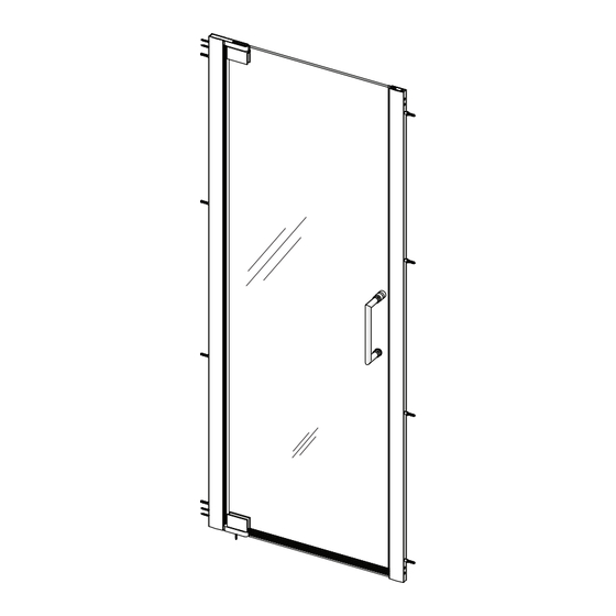
ELEGANCE/ELEGANCE-LS (STYLE A) SINGLE DOOR
S
HOWER
PLEASE REVIEW THIS ENTIRE MANUAL PRIOR TO INSTALLATION
Elegance
*left swing door installation shown
IMPORTANT!
DreamLine
reserves the right to alter, modify or redesign products at any time without prior notice for the
®
purpose of product improvement and customer experience. Please refer to the model's web page on
DreamLine.com for the latest technical drawings, installation manuals, warranty information or additional
product details.
Do Not Return Product to the Store. Contact DreamLine® with any questions
Please contact DreamLine Customer Support
Please contact DreamLine Customer Support
See DreamLine.com for hours of operation
See DreamLine.com for hours of operation
ELEGANCE/ELEGANCE-LS (Style A) Single Shower Door Manual Ver 2 Rev 1 112022
D
I
OOR
NSTALLATION
Model #s:
SHDR-4125720-##
SHDR-4127720-##
SHDR-4128720-##
SHDR-4130720-##
SHDR-4132720-##
SHDR-4134720-##
SHDR-4135720-##
I
NSTRUCTIONS
Elegance-LS
1-866-731-2244
1-866-731-2244
©2022 DreamLine® All Rights Reserved
Model #s:
SHDR-4325000-##
SHDR-4327000-##
SHDR-4328000-##
SHDR-4330000-##
SHDR-4332000-##
SHDR-4334000-##
SHDR-4335000-##
## = Finish:
01 = Chrome
04 = Brushed Nickel
06 = Oil-Rubbed Bronze
09 = Satin Black
Advertisement
Table of Contents

Related Manuals for Dreamline SHDR-4125720 Series


Summary of Contents for Dreamline SHDR-4125720 Series
- Page 1 ® purpose of product improvement and customer experience. Please refer to the model’s web page on DreamLine.com for the latest technical drawings, installation manuals, warranty information or additional product details. Do Not Return Product to the Store. Contact DreamLine® with any questions...
- Page 2 For best results, squeegee the glass after each use and dry with a soft cloth. Record the following purchase information for your records or in the event you need to contact DreamLine ® Purchase Order...
-
Page 3: Table Of Contents
Table of Contents Section Title Page # ® ClearMax Coating Information — Warnings and General Preparation Model Specific Preparation Tools Configurations Adjustable Wall Profile System Detailed Diagram of Shower Door Components Parts List Installation Steps 10-26 Strike Profile Installation Decorative Cover Installation Bottom Sweep Vinyl Installation Securing the Bottom Pivot Assembly to the Threshold (optional) Product Maintenance... -
Page 4: Warnings And General Preparation
• • DreamLine® reserves the right to alter, modify or redesign products any time without After opening all boxes and packages, read this introduction carefully. Check that all the prior notice for product improvement and customer experience. Please refer to the items are included in the package by marking off the components on the “Detailed... -
Page 5: Model Specific Preparation
Model Specific Preparation REQUIRED: 1” (25.4mm) maximum out-of-plumb adjustment per side. Verify finished ±0.0 ±0.0 walls with a level. Threshold must be level ±0.0 ±0.0 Tile Acrylic This model has an adjustable wall profile system that allows for up to 1” (25.4mm) per side for Contact the manufacturer of the base, tub or Out-of-Plumb wall conditions and threshold material with any questions regarding... -
Page 6: Tools
Diagram on page 7; and packing list in this manual as a reference. Before discarding the carton, check for small hardware bags that may have fallen to the bottom of the box. If any NOTE parts are damaged or missing, please contact DreamLine for replacement. The shipping ®... -
Page 7: Configurations
Single Door Elegance and Elegance-LS models are also available with inline panels in various widths. Panels 12” or larger include an L-Bar ™ . See all models at DreamLine.com *Left-Swing door installation shown This manual describes the single door installation of the ELEGANCE and ELEGANCE LS models. -
Page 8: Adjustable Wall Profile System
Two-Part Adjustable Wall Profile System Glass Pro le The Glass Profiles can be adjusted up to 1” Wall Pro le within the Wall Profiles for overall width or Vinyl to correct for out-of-plumb conditions within Insert the model size. Screw them together only after making final adjustments. -
Page 9: Detailed Diagram Of Shower Door Components
Detailed Diagram of Elegance Shower Door Components ©2022 DreamLine® All Rights Reserved ©2022 DreamLine® All Rights Reserved... -
Page 10: Parts List
Parts List Parts List bottom (Shorter) *handle styles may vary by model Elegance (Longer) bottom bottom 72”” 70-5/8”” ELEGANCE/ELEGANCE-LS (Style A) Single Shower Door Manual Ver 2 Rev 1 112022... - Page 11 Parts List The Pivot Assemblies are It is not necessary to fully disassemble paired and either one can be the Pivot Assemblies for installation. used as the top or bottom pivot depending on the Parts per Pivot Assembly-A handing of the door installation.
-
Page 12: Installation Steps
◾If no stud is present behind the wall: Tools Needed drill a Ø5/16”(7mm) hole and insert the Wall Anchors (#12) Large Truss Head Screw ST4.2 x 40 (#16) and use the Fig 1 ©2022 DreamLine® All Rights Reserved... - Page 13 Fig 2a Parts Needed Pivot Assembly-Top (#07) as viewed from outside bottom Tools Needed Fig 2b ©2022 DreamLine® All Rights Reserved...
- Page 14 Parts Needed bottom Tools Needed Fig 3 ©2022 DreamLine® All Rights Reserved...
- Page 15 NOTE NOTE (shorter) (#02), the Glass Profile used for the (#04), the Glass Profile used for the strike side hinge side of the shower door. of the shower door. Fig 4 left-swing door installation shown ©2022 DreamLine® All Rights Reserved...
- Page 16 NOTE Fig 5. The back of the Pivot Assembly and the bolts face the inside of the shower. Tools Needed The Glass Profile Hinge Side (#02) is the shorter of NOTE the two Glass Profiles. ©2022 DreamLine® All Rights Reserved...
- Page 17 Bottom Sweep Vinyl) (#11). Identify this difference to prevent installing the Door Glass upside-down. Tools Needed Use caution when handling the Door Glass (#03). left-swing door installation shown DO NOT lift the Door Glass with the Handle (#06). ©2022 DreamLine® All Rights Reserved...
- Page 18 Tools Needed Each two-piece wall profile system (consisting of the Glass Profiles (#02/04) and Wall Profiles (#01/05)) will allow for 1” of adjustment for overall width or an out-of-plumb condition within the model size. ©2022 DreamLine® All Rights Reserved...
- Page 19 Handle Assembly Installation: Elegance inside Parts Needed left-swing door installation shown Fig 8 Tools Needed Tighten both knobs to the Handle (#06) to ensure the handle is secured to the Door Glass (#03). (see Fig 7.3) ©2022 DreamLine® All Rights Reserved...
- Page 20 Handle Assembly Installation: Elegance-LS sideview inside Parts Needed Fig 8a left-swing door installation shown Tools Needed Tighten all four Handle (#06 LS) set screws to ensure the handle is secured to the Door Glass (#03). (see Fig 7.3)
- Page 21 Pivot Assembly (#07) down into the threshold. See Page 27 for specific instructions. left-swing door installation shown Tools Needed When installing the door along with an inline panel model, postpone this step until after aligning the panel glass. ©2022 DreamLine® All Rights Reserved...
-
Page 22: Strike Profile Installation
If installing this door along with an inline panel, stop here and refer to the manual that came with the panel glass for further installation instructions. Otherwise, for a single door, continue with Step 10 below. Glass Pro le Wall Pro le Parts Needed Fig 10 ©2022 DreamLine® All Rights Reserved... - Page 23 Fig 11 left-swing door installation shown ◾If no stud is present behind the wall: drill a Ø5/16”(7mm) hole and insert the Wall Anchors (#10) and use the ST4.0 x 40mm Pan Head Screws (#08). ©2022 DreamLine® All Rights Reserved...
- Page 24 Parts Needed Fig 12 Tools Needed ©2022 DreamLine® All Rights Reserved...
- Page 25 1” (25mm) Max. Dot not exceed Maximum Adjustment of 1” (25mm) per side Parts Needed left-swing door installation shown Fig 13 Tools Needed Use caution not to damage the edges of the door glass during adjustments. ©2022 DreamLine® All Rights Reserved...
-
Page 26: Decorative Cover Installation
Ø1/8” drill bit. Turn to Page 27 for instructions to screw the bottom Pivot Assembly (#7) to left-swing door installation the threshold if desired. Otherwise, continue on to the next step. shown from the inside ©2022 DreamLine® All Rights Reserved... -
Page 27: Bottom Sweep Vinyl Installation
Close the door, mark and notch the inner aspect only of the inner-side of the Bottom Sweep (#11) where it overlaps the Snap-in Anti-Water Strip (#10) when the door is in the closed position. (Fig 15b.1) Tools Needed ©2022 DreamLine® All Rights Reserved... - Page 28 Note that the strike side Glass Profile (longer) (#04) and Wall Profile Strike Side (longer) (#05) will not be used with the inline panel installation. Fig 16 Tools Needed Allow 24 hours for the silicone caulk to cure before using the shower. ©2022 DreamLine® All Rights Reserved...
-
Page 29: Securing The Bottom Pivot Assembly To The Threshold (Optional)
◾For installation into a Tile Threshold: drill a Ø3/16”(4mm) hole up to the stud, drill an Ø1/8”(3mm) Use caution not to scratch the hinge NOTE pilot hole and use the ST4.2×40mm Countersunk Screw surface. (#01.9 / 02.9). ©2022 DreamLine® All Rights Reserved... -
Page 30: Product Maintenance
To maximize the life of your door, it is important to regularly inspect the glass and other hardware for misalignment, proper attachment, NOTE and/or damage. Contact DreamLine with any questions or concerns. ® ELEGANCE / ELEGANCE-LS Single Door Maintenance Checklist ◻... -
Page 31: Troubleshooting
Suggested Solution Page(s) •Check all shipping/packaging material for missing parts/components. Missing Parts •If not found, contact DreamLine Customer Support [1-866-731-2244] to order —— factory part replacement. • Inspect the Bottom Sweep Vinyl (#11) and ensure the orientation of the vinyl is installed correctly. -
Page 32: Factory Parts Information
BOLD digit indicates finish color: 1 = Chrome 4 = Brushed Nickel 6 = Oil-Rubbed Bronze 9 = Satin Black Contact Support@DreamLine.com for Part replacement, installation assistance or additional information. Complete Warranty information is available on DreamLine.com. ©2022 DreamLine® All Rights Reserved... - Page 33 35-3/4" - 37-3/4" ELEGANCE {SHDR-4135720-##} FACTORY PARTS INFORMATION ITEM # FACTORY PART NUMBER ITEM DESCRIPTION 010071008 Door Glass 1 pc Contact Support@DreamLine.com for Part replacement, installation assistance or additional information. Complete Warranty information is available on DreamLine.com. ©2022 DreamLine® All Rights Reserved...
- Page 34 32-1/4" - 34-1/4" ELEGANCE {SHDR-4332000-##} FACTORY PARTS INFORMATION ITEM # FACTORY PART NUMBER ITEM DESCRIPTION 010071008 Door Glass 1 pc Contact Support@DreamLine.com for Part replacement, installation assistance or additional information. Complete Warranty information is available on DreamLine.com. ©2022 DreamLine® All Rights Reserved...
- Page 35 NOTES ©2022 DreamLine® All Rights Reserved...
- Page 36 TEL: 866-731-2244 FAX: 866-857-3638 DREAMLINE.COM For more information on DreamLine Shower Doors and Enclosures please visit DreamLine.com ® ©2022 DreamLine® All Rights Reserved...
Need help?
Do you have a question about the SHDR-4125720 Series and is the answer not in the manual?
Questions and answers