NEC DSX-160 Hardware Manual
Hide thumbs
Also See for DSX-160:
- Parts list (4 pages) ,
- Quick start manual (2 pages) ,
- Hardware manual (2 pages)
Table of Contents
Advertisement
Quick Links
Empowered by Innovation
Upgrading from DS2000 to DSX-80/160
If upgrading from DS2000 to DSX-80/160, be sure to carefully review Upgrading
DS2000 to DSX-80/160 (P/N 1093077) prior to the upgrade.
DSX-80/160 Hardware
Manual
P/N 1093096
Rev 2, June 2006
Printed in U.S.A
.
01.00.00
For additional resources, visit our Technical Support site on the web at
.
http://www.necdsx.com
Advertisement
Table of Contents

Related Manuals for NEC DSX-160


Summary of Contents for NEC DSX-160
- Page 1 Empowered by Innovation Upgrading from DS2000 to DSX-80/160 If upgrading from DS2000 to DSX-80/160, be sure to carefully review Upgrading DS2000 to DSX-80/160 (P/N 1093077) prior to the upgrade. DSX-80/160 Hardware Manual P/N 1093096 Rev 2, June 2006 Printed in U.S.A 01.00.00 For additional resources, visit our Technical Support site on the web at http://www.necdsx.com...
- Page 2 This manual has been developed by NEC Unified Solutions, Inc. It is intended for the use of its customers and service personnel, and should be read in its entirety before attempting to install or program the system. Any comments or suggestions for improving this manual would be appreciated.
-
Page 3: Table Of Contents
NEC / Plantronics Headsets ........ - Page 4 Table of Contents Installation ............21 System Preparation .
- Page 5 Table of Contents Reinstalling the Side Panel........... . 52 Reinstalling the Front Cover .
- Page 6 Table of Contents iv ◆ Table of Contents DSX-80/160 Hardware Manual...
-
Page 7: Components
DSX Telephones Components DSX Telephones DSX Telephones 22-Button Display Telephone with Speakerphone P/Ns 1090020 (Black) and 1090025 (White) Display: 3 line x 24 character Speakerphone: Built-in, half-duplex Soft Keys: 4 Wall Mount: Built-in Feature Keys: 12 Angle Adjustment: 2 position built-in Fixed Function Keys: 12 Backlit: No Speed Dial Bin Keys: 10... -
Page 8: 34-Button Backlit Display Telephone With Full-Duplex Speakerphone
DSX Telephones 34-Button Backlit Display Telephone with Full-Duplex Speakerphone P/Ns 1090022 (Black) and 1090027 (White) Display: 3 line x 24 character Speakerphone: Built-in, full-duplex Soft Keys: 4 Wall Mount: Built-in Feature Keys: 24 Angle Adjustment: 2 position built-in Fixed Function Keys: 12 Backlit: Yes Speed Dial Bin Keys: 10 Dual LEDs: Yes... -
Page 9: Single Line Telephones
Single Line Telephones Single Line Telephones DTH-1-1 Single Line Telephone P/N 780034 (Black) Fixed Function Keys: 5 Message Waiting: Yes Speed Dial Bin Keys: 4 Ring/Message Waiting Lamp: Yes Selectable Ring Tones: Yes Wall Mount: Built-in The DTH-1-1 is a cost-effective analog single line telephone that offers 5 fixed feature keys, 4 Speed Dial bin keys and Message Waiting. -
Page 10: Dsx Cordless Telephone
DSX Cordless Telephone DSX Cordless Telephone DSX Cordless Lite II P/N 730087 Display: 2 line x 16 character Transmission: 900 MHz Narrow Band FM Status Icons: 4 Range: 350 feet (site dependent) Feature Keys: 4 Max Units Per Site: 30 (12 in close proximity) Fixed Function Keys: 8 Battery Life: Up to 7 hours talk time Channels: 30... -
Page 11: Headsets
Corded Headsets for DSX Keysets and DTR/DTH SLTs The following corded headsets are compatible with DSX keysets and the DTR/DTH single line telephones. Check with your supplier for their latest offerings. NEC / Plantronics Headsets NEC / Plantronics Amplified Headsets Plantronics Model NEC P/N Description... - Page 12 Headsets NEC / Plantronics Non-Amplified Headsets Plantronics Model NEC P/N Description Style Microphone Type Number Voice Tube StarSet In-the-Ear Noise Canceling H31N Voice Tube Mirage On-the-Ear Noise Canceling H41N Voice Tube Supra Monaural Over-the-Head Noise Canceling H51N Voice Tube Supra Binaural...
-
Page 13: Gn Netcom Headsets
Headsets GN Netcom Headsets GN Netcom Non-Amplified Headsets Model Number Description Microphone Type Style GN 2110 STD01 2100 Sound Tube Monaural Sound-Tube Over-the-Head GN 2120 NCD01 2100 Flex Monaural Noise-Canceling Over-the-Head GN 2115 STD01 2100 SoundTube Binaural Sound-Tube Over-the-Head GN 2125 NCD01 2100 Flex Binaural Noise-Canceling Over-the-Head... -
Page 14: Headsets For Dsx Cordless Lite Ii Telephone
Headsets Headsets for DSX Cordless Lite II Telephone P/N 750637 (M175) P/N 750642 (MX150) The following headsets are available for the DSX Cordless Lite II Telephone: • M175 Headband Style (P/N 750637) • MX150 Earloop Style (P/N 750642) 8 ◆ Components DSX-80/160 Hardware Manual... -
Page 15: Desi Telephone Label System
- 22-Button Display Standard - 34-Button Display Standard - 34-Button Super Display Standard - 60-Button DSS Console Standard The following DESI labels are available for the NEC analog single line telephones. • For DTR-1-1 - Black (P/N 780400) - Metallic green (P/N 780401) - Page 16 DESI Telephone Label System • For DTR-1HM-1 - Black (P/N 780404) - Metallic green (P/N 780405) - Metallic silver (P/N 780406) - Lime green (P/N 780407) - Preprint (blank) (P/N 780460) • For DTH-1-1 - Metallic silver (P/N 780450) 10 ◆ Components DSX-80/160 Hardware Manual...
-
Page 17: Dsx-80/160 Common Equipment
DSX-80/160 Common Equipment DSX-80/160 Common Equipment DSX-80 4-Slot KSU P/N 1090002 Slots: 4 Analog extensions (max.): 48 Ports: 80 Analog lines (max): 48 Digital extensions (max.): 32 Digital (T1) lines (max.): 64 • Capacities determined by System Load Factor. • Always install a 16ESIU Card in the first universal slot. -
Page 18: Dsx-80/160 Cpu
DSX-80/160 CPU DSX-80/160 CPU DSX-80/160 CPU Card P/N 1090010 Audio Inputs: 2 RS 232 connector: Yes (for SMDR) Audio outputs: 1 Ethernet port: Yes USB connector: Yes CompactFlash interface: Yes The CPU Card is the system’s control center. It provides the system’s Linux operating system, central pro- cessing, stored program, and memory for the customer’s site-specific data. -
Page 19: Dsx-80/160 Station Cards
DSX-80/160 Station Cards DSX-80/160 Station Cards DSX-80/160 16 Port Digital Station (16ESIU) Card P/N 1091004 Digital station ports: 16 Status LED: Yes Mode switch: Yes Activity LED: Yes Max. installed in DSX-80: 2 (32 station Max. installed in DSX-160: 6 (96 station ports) ports) Each 16ESIU Card connects 16 digital extensions (i.e., DSX keysets). -
Page 20: Dsx-80/160 8 Port Analog Station (8Sliu) Card With Hv Message Waiting
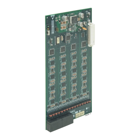
DSX-80/160 Station Cards DSX-80/160 8 Port Analog Station (8SLIU) Card with HV Message Waiting P/N 1091010 Analog station ports: 8 Activity LED: Yes High Voltage Message Waiting: Yes Mode switch: Yes Max. installed in DSX-80: 3 (24 station Status LED: Yes ports) Max. -
Page 21: Dsx-80/160 Line Cards
DSX-80/160 Line Cards DSX-80/160 Line Cards DSX-80/160 T1/E1/PRI Line Card P/N 1091006 Line ports: 24 Activity LED: Yes Mode switch: Yes Diagnostic LEDs: Yes Status LED: Yes CSU required: Yes Max. installed in DSX-80: 3 (64 line ports Max. installed in DSX-160: 3 (64 line ports in 3 T1/E1/PRI Cards, with 8 T1 circuits in 3 T1/E1/PRI Cards, with 8 T1 circuits disabled in programming) -
Page 22: Dsx-80/160 8 Port Co Line (8Coiu) Card With Caller Id
DSX-80/160 Line Cards DSX-80/160 8 Port CO Line (8COIU) Card with Caller ID P/N 1091009 Line ports: 8 Status LED: Yes Mode switch: Yes Activity LED: Yes Power Failure ports: 2 Caller ID: Built in Max. installed in DSX-80: 3 (24 line ports Max. -
Page 23: Intramail
IntraMail IntraMail DSX IntraMail 8 x 16 P/N 1091013 Ports: 8 Storage Hours: 16 Routing Mailboxes: 16 Subscirber Mailboxes: 128 Ring Group Mailboxes: 8 UCD Group Mailboxes: 8 Total Mailboxes: 160 DSX IntraMail 4 x 8 P/N 1091011 Ports: 4 Storage Hours: 8 Routing Mailboxes: 16 Subscirber Mailboxes: 128... -
Page 24: Miscellaneous Cards And Optional Equipment
Miscellaneous Cards and Optional Equipment Miscellaneous Cards and Optional Equipment DSX Analog Door Box P/N 922450 Requires 2PGDAD Module connected to DSX-80/160: No built-in Door Box ports. DSX Digital Station (16ESIU) PCB. The Analog Door Box is a self-contained Intercom unit typically used to monitor an entrance door. A visitor at the door can press the Door Box call button (like a door bell). -
Page 25: System Configuration
System Configuration System Configuration DSX-80/160 System Load Factor The combination of lines and extensions you can connect to your DSX system may be limited by the System Load Factor. Use the DSX-80/160 System Load Factor Worksheet on the next page to verify your system’s configuration. - Page 26 System Configuration DSX-80/160 System Load Factor Worksheet Load Type Description 5 VDC 40 VDC Load Total Load Total CPU Card 16ESIU Card 8SLIU Card 16SLIU Card 8COIU Card 16COIU Card T1/E1/PRI Card Item 1: Load Type Totals (Cannot exceed Item 2: Power Supply Capacity.) Item 2: Power Supply Capacity If you have one power supply installed, the capacity is: 5 VDC = 40...
-
Page 27: Installation
Installation System Preparation System Preparation Unpacking Unpack the equipment and check it against your equipment lists. Inspect for physical damage. If you are not sure about a component’s function, review Components (page 1). Contact your Sales Representative if you have additional questions. Have the appropriate tools for the job on hand, including: a test set, a punch down tool and a digital voltmeter. -
Page 28: Installing The Main Equipment Cabinet
Installing the Main Equipment Cabinet Installing the Main Equipment Cabinet Planning the Installation Before installing the common equipment, you should mount a Main Distribution Frame (MDF) plywood back- board in a centrally located spot. A 1/2 sheet of plywood (4’ x 4’) should be adequate for a DSX-80 4-Slot KSU. -
Page 29: Removing The Cover
Installing the Main Equipment Cabinet Line Blocks Note: The system will respond to telco ring signal in the range of 40-130 VAC @ 20 Hz. Station Station Blocks Blocks Dedicated AC Outlet Surge To telco To earth Protector ground ground Figure 2: Installation Layout, DSX-160 Removing the Cover Before wall-mounting, remove the cover on the Main Equipment Cabinet. -
Page 30: Unpacking The Wall Mount Bracket
Installing the Main Equipment Cabinet Unpacking the Wall Mount Bracket The wall mount bracket and screws are taped to the packing material in the Main Equipment Cabinet box. Unpack the wall mount bracket and mounting screws. Figure 4: Wall Mount Bracket Mounting the Wall Mount Bracket Mount the wall mount bracket on the MDF in a convenient location, about 12”... -
Page 31: Hanging The Cabinet
Installing the Main Equipment Cabinet Hanging the Cabinet To hang the cabinet: Hang the Main Equipment Cabinet on the wall mount hanger(s) as shown: - See Figure 6: Hanging the DSX-80 4-Slot KSU below when hanging a DSX-80 4-Slot KSU. - See Figure 7: Hanging the DSX-160 8-Slot KSU below when hanging an DSX-160 slot cabinet. -
Page 32: Grounding The Cabinet
Grounding the Cabinet Grounding the Cabinet Removing the Right Side Panel Remove the cabinet right side panel to gain easy access to the ground lugs and system cabling. The cabinet has two ground connections: ETH (Earth Ground) and PBXG (PBX Ground). To remove the right side panel: Remove the two screws that secure the right side panel to the cabinet. -
Page 33: Attaching The Ground Wire
Grounding the Cabinet Attaching the Ground Wire Important You must connect your system to a known earth ground. There are three ground terminations on the KSU: signal, earth, and PBX. You must connect all three termi- nations to a known good earth ground using 12 AWG stranded copper wire. To attach the ground wires: Remove the lugs on the earth and PBX ground terminations. -
Page 34: Installing The Rfi Suppressor Assembly
Grounding the Cabinet Installing the RFI Suppressor Assembly You must install an RFI Suppressor Assembly for the CPU audio and ethernet cables. The suppressor must be mounted inside the cabinet and as close the CPU Card as possible. Figure 10: Installing the RFI Suppressor Assembly 28 ◆... -
Page 35: Installing The Power Supply
Installing the Power Supply Installing the Power Supply Power Supply Installation The power supply provides the DC power sources required to operate the system. To install a power supply: Slide the power supply into the CN101 slot. Using a long-shaft phillips head screwdriver, tighten the two screws that secure the power supply. A DSX-160 may require up to 3 power supplies (depending on system configuration), using slots CN101, CN102 and CN103. -
Page 36: Installing Cards
The CPU Card installs in the CN0 slot in the Main Equipment Cabinet. To install the CPU Card: Insert the battery (Sony CR2032 or NEC P/N EX0254-0040) into the battery clips. Plug the CPU into slot CN0 . • Refer to Installing Optional Equipment (page 57) when connecting the audio inputs and outputs to the CPU Card. -
Page 37: Installing The 16Esiu Digital Station Cards
Installing Cards Installing the 16ESIU Digital Station Cards The 16ESIU provides the connection for 16 digital telephones. It also provides connection for DSS Consoles (four max per system). To install 16ESIU Cards: Plug the 16ESIU Card for extensions 300-315 into slot Plug in additional ESIU Cards as required. -
Page 38: Connecting 16Esiu Cards
Installing Cards Connecting 16ESIU Cards The 16ESIU Card, just like the COI and SLI Cards, uses 8-pin mod jacks to connect extensions. Using the Installation Cable (P/N 808920) makes it easy to connect the cards to standard 66M1-50 connecting blocks. These cables have six 8-pin modular jacks on one end and are unterminated on the other. -
Page 39: Installing 16Sliu And 8Sliu Analog Station Cards
Installing Cards Installing 16SLIU and 8SLIU Analog Station Cards The 16SLIU connects 16 analog telephones. The 8SLIU connects for 8 analog telephones. To install a SLIU Card: Turn to System Preparation (page 21) to be sure you haven’t exceeded the allowable system load factor. Plug a SLIU Card into any available slot from CN2-CN8 - You should reserve... -
Page 40: Connecting 16Sliu And 8Sliu Cards
Installing Cards Connecting 16SLIU and 8SLIU Cards The SLIU Card, just like the COI and16ESIU Cards, uses 8-pin mod jacks to connect extensions. Using the Installation Cable (P/N 808920) makes it easy to connect the cards to standard 66M1-50 connecting blocks. These cables have six 8-pin modular jacks on one end and are unterminated on the other. -
Page 41: Installing 16Coiu And 8Coiu Analog Line Cards
Installing Cards Installing 16COIU and 8COIU Analog Line Cards The 16COIU connects 16 analog loop start lines. The 8SCOIU connects 8 analog loop start lines. To install a COIU Card: Turn to System Preparation (page 21) to be sure you haven’t exceeded the allowable system load factor. Plug a COIU Card into any available slot from CN2-CN8 - You should reserve... -
Page 42: Connecting 16Coiu And 8Coiu Cards
Installing Cards Connecting 16COIU and 8COIU Cards The COIU Card, just like the SLI and16ESIU Cards, uses 8-pin mod jacks to connect extensions. Using the Installation Cable (P/N 808920) makes it easy to connect the cards to standard 66M1-50 connecting blocks. These cables have six 8-pin modular jacks on one end and are unterminated on the other. -
Page 43: Installing T1/E1/Pri Cards
Installing Cards Installing T1/E1/PRI Cards Normally you connect the T1/E1/PRI Card to a separately-purchased Channel Service Unit (CSU). Use a standard straight-through CAT 5 cable to connect the T1/E1/PRI Card to the CSU. The CSU in turn connects to the telco smart jack. The T1/E1/PRI Card also provides 32E1 support. -
Page 44: Connecting The T1/E1/Pri Card
Installing Cards Connecting the T1/E1/PRI Card To install the T1/E1/PRI Card: Turn to System Preparation (page 21) to be sure you haven’t exceeded the allowable system load factor. Set jumpers CN7 and CN9 to the T1 position. - CN7 and CN9 are not required for T1 installations. You can optionally leave them off. Plug in T1/E1/PRI Trunk Cards as required. -
Page 45: Securing The Cables
Installing Cards Securing the Cables After you have punched down your cables, route them through the side of the cabinet and secure them with the strain relief. Figure 21: Securing the Cables Making Your Own Cables Making Your Own Installation Cables The following products should help if you make your own cables. -
Page 46: Making A T1/E1/Pri Crossover Cable
Installing Cards Making a T1/E1/PRI Crossover Cable If you don’t have a T1 Tester, you can alternately test Tie Line operation between two T1/E1/PRI Cards in the same cabinet or facility using the cable shown below. Using this same setup, you can loop a Tie Line to a DID Line to test your DID routing before connecting to the CSU. -
Page 47: Connecting Extensions And Setting Up The Telephone
Connecting Extensions and Setting Up the Telephone Connecting Extensions and Setting Up the Telephone Connecting Extensions Each 16ESIU Card connects 16 digital extensions. Each 16SLIU Card connects 16 analog extensions, and each 8SLIU Card connects 8 analog extensions. To connect extensions: Using Figure 14: Connecting 16ESIU Digital Station Cards (page 32) and Figure 16: Connecting 16SLIU and 8SLIU Cards (page 34) as a guide, plug the installation cable mod jacks into the appropriate connectors on the station cards. -
Page 48: Installing The Dsx Keyset Handset And Line Cord
Connecting Extensions and Setting Up the Telephone Installing the DSX Keyset Handset and Line Cord. When installing the handset, plug the handset cord into the handset jack on the bottom of the telephone. The handset cord routes through the lower channel on the right side of the telephone base. The line cord does not use a channel and drapes down from the telephone line cord jack or connects to the telephone legs. -
Page 49: Installing The Dss Console Line Cord
Connecting Extensions and Setting Up the Telephone Installing the DSS Console Line Cord The DSS Console connects to an available port on an 16ESIU Card, just like a keyset. You can install four maximum per system. The DSS Console line cord does not use a channel and drapes down from the tele- phone line cord jack or connects to the telephone legs. -
Page 50: Keyset And Dss Console Two Position Angle Adjustment
Connecting Extensions and Setting Up the Telephone Keyset and DSS Console Two Position Angle Adjustment To set the low viewing angle position: Fold the legs all the way back. Figure 28: Setting the Low Viewing Angle To set the high viewing angle position: Flip up the two leg supports. -
Page 51: Removing The Faceplate
Connecting Extensions and Setting Up the Telephone Removing the Faceplate You’ll need to remove the telephone faceplate to write on the label or install a DESI custom label. To remove the faceplate: Put your finger in the recessed area under the faceplate and lift off the faceplate. Figure 30: Removing the Telephone Faceplate Installation ◆... - Page 52 Connecting Extensions and Setting Up the Telephone To reinstall the faceplate: Snap back into place as shown. Figure 31: Reinstalling the Telephone Faceplate 46 ◆ Installation DSX-80/160 Hardware Manual...
-
Page 53: Connecting Lines
Connecting Lines Connecting Lines Connecting Analog Lines Each 16COIU Card connects 16 loop start CO trunks. Each 8COIU Card connects 8 loop start CO trunks. To connect analog trunks: Using Figure 18: Connecting 16COIU and 8COIU Cards (page 36) as a guide, plug the installation cable mod jacks into the appropriate connectors on the COIU Cards. -
Page 54: Powering Up The System
Powering Up the System Powering Up the System Before Powering Up The system’s built-in Automatic Slot Configuration automatically sets up station and line cards when you initially power up the system. On power up, the system scans the cards from left to right and sets up the sta- tion and line numbering as follows: Extension numbers will begin with 300 in the first slot and increment from left to right. -
Page 55: System Leds
Powering Up the System System LEDs Power Supply LEDs + 5 V DC (Green) On: +5 V DC power present. Off: +5 V DC power not present. - 5 V DC (Green) On: -5 V DC power present. Off: -5 V DC power not present. - 40 V DC (Green) On: -40 V DC power present. -
Page 56: Digital Station (Esiu), Analog Station (Sliu), And Analog Line (Coiu) Card Leds
Powering Up the System Digital Station (ESIU), Analog Station (SLIU), and Analog Line (COIU) Card LEDs Sync Status (green) Fast Flash: PCB running, waiting for sync. Same as having the mode switch set to stop. System has an error. Slow Flash: PCB running, in sync. -
Page 57: T1/E1/Pri Card Leds
Powering Up the System T1/E1/PRI Card LEDs (Yellow) (Green) Port Activity PCB Running Off: All ports on PCB idle. Slow flash: T1 PCB running. Flash: Port(s) busy. The faster the flash, the more T1 PCB starting. ports are busy. (Green) Sync (Master) Off: T1 PCB is in the slave mode (i.e., getting the... -
Page 58: Finishing The Installation
Finishing the Installation Finishing the Installation Reinstalling the Side Panel To reinstall the side panel: Carefully realign the right side panel and slide it into position. Reattach the two screws that secure the right side panel to the cabinet. DSX-80 4-Slot KSU Shown Figure 37: Reinstalling the Side Panel 52 ◆... -
Page 59: Reinstalling The Front Cover
Finishing the Installation Reinstalling the Front Cover To reinstall the front cover: Hook the tabs on the rear of the cover into their associated slots. Push the front of the cover into place. Screw in the two captive screws that secure the cover to the cabinet. Figure 38: Reinstalling the Front Cover Installation ◆... -
Page 60: Resetting And Initializing The System
Resetting and Initializing the System Resetting and Initializing the System Resetting the System To reset the system: Important If the system’s RS-232 connection uses twisted pair cable, before resetting do one of the following: • Make sure the RS-232 cable is connected at both ends (i.e., PC and CPU). •... -
Page 61: Initializing The System
Resetting and Initializing the System Initializing the System To initialize (cold start) the system: - This erases all your stored programming and returns the system to its default settings. Turn off the system. Press and hold the Reset Switch on the CPU while turning on the system power. When all the LEDs on the CPU light and then go out, release the Reset Switch - The system will restart with the default settings. -
Page 62: Upgrading The System Software
Upgrading the System Software Upgrading the System Software Upgrade System Software To upgrade system software from a CompactFlash card: Remove the IntraMail CompactFlash card (if installed), then insert the CompactFlash card containing the system software into the CPU. - Although advisable, backing up the site programming is not required. Press and hold the Reset Switch on the CPU. -
Page 63: Installing Optional Equipment
Installing Optional Equipment Installing IntraMail Installing IntraMail Setting Up IntraMail for the First Time A default system (with no voice mail installed) provides the Built-In Automated Attendant. See Automated Attendant, ■ Built-In in the IntraMail section of the System Guide for more. If you have another (external) voice mail installed, you must disconnect and unprogram it before installing IntraMail. -
Page 64: Installing A Dsx Analog Door Box And 2Pgdad Module
Installing a DSX Analog Door Box and 2PGDAD Module Installing a DSX Analog Door Box and 2PGDAD Module Connecting a DSX Analog Door Box to the 2PGDAD Module The DSX Analog Door Box (P/N 922450) is a self-contained, weather-tight Intercom unit typically used to monitor an entrance door. -
Page 65: Connecting Door Boxes And Relays
Installing a DSX Analog Door Box and 2PGDAD Module Connecting Door Boxes and Relays To connect a Door Box: Find a suitable location for the DSX Analog Door Box. - The door box is a weather-tight unit and can be installed outdoors. Run one-pair 24 AWG station cable from the door box to the 2PGDAD Module. -
Page 66: Mounting The 2Pgdad Module And Connecting To The System
Installing a DSX Analog Door Box and 2PGDAD Module Mounting the 2PGDAD Module and Connecting to the System To mount and connect the 2PGDAD Module: Mount two suitable fasteners (such as #8 sheet metal screws) about 3 15/16” apart either horizontally (for horizontal mounting) or vertically (for vertical mounting). -
Page 67: External Paging
External Paging External Paging Installing External Paging The CPU provides an External Paging output. You connect the CPU Paging output to an audio input on a customer provided Paging system. Be sure the connected Paging equipment is compatible with the following page output specifications: External Paging Output Specifications Output Impedance:... -
Page 68: Music Source
Music Source Music Source Installing a Music Source Your system provides two connections for customer provided music sources. Use these music sources for Background Music and Music on Hold. Be sure the connected music sources are compatible with the follow- ing music input specifications: Music Input Specifications Input Impedance:... -
Page 69: Power Failure Telephone
Power Failure Telephone Power Failure Telephone Power Failure Cut-Through When AC power fails, the system can automatically cut through to a Power Failure Telephone connection. Each COIU Card has two power failure cut-though connections. To install Power Failure Cut-Through: Locate an available 8-pin jack in a line or station block. - Local codes may prevent you from using a connector on a line block for optional equipment. -
Page 70: Wall Mounting
Wall Mounting Wall Mounting Reversing the Handset Hanger Before wall mounting your DSX telephone, you should reverse the handset hanger. The hanger holds the handset in place while the telephone is mounted on the wall. To reverse the wall-mount handset hanger: Slide out the handset hanger. -
Page 71: Wall Mounting A Keyset
Wall Mounting Wall Mounting a Keyset Wall Mounting a Keyset on a Standard Wall Plate To mount the telephone on the standard wall plate: Locate and wire a standard wall plate in a convenient location. Fold the telephone legs into the wall mount position. Make sure the handset coil cord is routed through the lower channel in the base. -
Page 72: Wall Mounting A Keyset Directly On The Wall
Wall Mounting Wall Mounting a Keyset Directly on the Wall To mount the telephone directly on the wall: Mount two suitable fasteners (such as #8 sheet metal screws) about 3 15/16” apart vertically. - Leave the heads exposed about 1/4”. Fold the telephone legs into the wall mount position. -
Page 73: Wall Mounting A Dss Console
Wall Mounting Wall Mounting a DSS Console Wall Mounting a DSS Console on a Standard Wall Plate To mount the DSS Console on the standard wall plate: Locate and wire a standard wall plate in a convenient location. Fold the DSS Console legs into the wall mount position. Fold the two leg supports down flush with the legs. -
Page 74: Wall Mounting A Dss Console Directly On The Wall
Wall Mounting Wall Mounting a DSS Console Directly on the Wall To mount the DSS Console directly on the wall: Mount two suitable fasteners (such as #8 sheet metal screws) about 3 15/16” apart vertically. - Leave the heads exposed about 1/4”. Fold the DSS Console legs into the wall mount position. -
Page 75: Keyset Self Test
Keyset Self Test Keyset Self Test Testing the Keyset Each DSX keyset has a built-in Self Test Diagnostic. Use this diagnostic to verify that each key is working, check the lamps (LEDs) in each key, and play back some system tones. To start the Self Test Diagnostic Unplug the keyset’s line cord. -
Page 76: Connecting A Pc To The System
Connecting a PC to the System Connecting a PC to the System Connections for PC Programming (System Administrator) and SMDR Use the USB or Ethernet port when connecting a PC locally for the System Administrator. Use the serial port only for SMDR. Adaptor, DB9 Female to Mod 6 Jack Ethernet (auto-sensing) Serial Port Standard A-B... -
Page 77: Specifications And Parts
Specifications and Parts Specifications Specifications (Page 1 of 2) System Capacities Cabinets: Talk Timeslots (Intercom/line): Non-blocking Ports Lines: Digital Telephones: DSX-80: 32 DSX-160: 96 Analog Telephones: DSX-80: 48 DSX-160: 80 DSS Consoles: 4 max. per system Plugs into a digital station port Power Failure Telephones: 2 per COIU Card Internal Paging Zones:... - Page 78 Specifications (Page 2 of 2) System Capacities 16ESIU Digital Station Card Refer to System Configuration (page 19) for 16SLIU Analog Station Card capacities. 8SLIU Analog Station Card 16COIU Analog CO Line Card 8COIU Analog CO Line Card T1/E1/PRI Card CPU Card: Environmental Requirements Meeting established environmental standards maximizes the life of the system.
- Page 79 Specifications Telephone and Line Voltages Keyset Voltages DC voltage measured at the MDF (between tip Minimum: 36 VDC and ring) Maximum: 44 VDC Minimum operating DC voltage measured at 24 VDC station jack (between tip and ring) 8/16SLIU Card Single Line Telephone Voltages DC voltage measured at the MDF (between tip On-Hook Idle State Minimum: 44 VDC and ring)
- Page 80 Specifications Mechanical Specifications Equipment Width Depth Height Weight 4 Slot KSU: 10 3/4” 5 7/8” 13 11/16” 4 lbs 5 oz 8 Slot KSU 19 1/2” 5 7/8” 13 11/16” 6 lbs 12 oz Display Keyset: 7 5/8” 9 1/2” 4 3/4”...
- Page 81 Specifications FCC Registration Information Model: DX7NA-80M and DSX7NA-160M Manufacturer: NEC Infrontia FCC Part 15 Registration: Class A FCC Registration Number: US:NIFKF00BDSX US:NIFMF00BDSX US:NIFPF00BDSX Industry Canada Certificate (DOC) Number: IC: 140k-DSX Reg. Status Mfrs. Port ID Network Jacks Original 02LS2 1091005 REN 0.6B...
-
Page 82: Parts List
Parts List Parts List Station Equipment Description Part Number 22-Button Display Telephone with Speakerphone 1090020 (Black) 1090025 (White) 34-Button Backlit Display Telephone with Speakerphone 1090021 (Black) 1090026 (White) 34-Button Backlit Display Telephone with Full-Duplex Speaker- 1090022 (Black) phone 1090027 (White) 34-Button Backlit Super Display Telephone with Half-Duplex 1090030 (Black) Speakerphone... - Page 83 Parts List DESI Labels Description Part Number DSX Telephone Labels DSX 22-Button Display Telephone (White) 1093086 DSX 22-Button Display Telephone (Black) 1093085 DSX 34-Button Display Telephone (White) 1093084 DSX 34-Button Display Telephone (Black) 1093083 DSX 34-Button Super Display Telephone (White) 1093082 DSX 34-Button Super Display Telephone (Black) 1093081...
- Page 84 Parts List Common Equipment Description Part Number DSX-80 4-Slot KSU 1090002 DSX-160 8-Slot KSU 1090003 DSX Power Supply 1091008 Installation Cable 808920 DSX Serial Adaptor 1091014 (requires customer-provided 6-conductor line cord) Cards Description Part Number CPU Card 1090010 16 Port Digital Station Card (16ESIU) 1091004 16 Port Analog Station Card with HV Message Waiting 1091007...
- Page 85 Parts List Replacement Parts Description Part Number Handset and Cord Assembly 1091016 22 Button Clear Plastic Cover 1091018 34 Button Clear Plastic Cover 1091019 34 Button Super Display Clear Plastic Cover 1091020 60 Button DSS Clear Plastic Cover 1091021 RFI Bead Kit 88901 Replacement Battery for CPU Card EX0254-0040...
- Page 86 Parts List 80 ◆ Specifications and Parts DSX-80/160 Hardware Manual...
- Page 87 NEC Unified Solutions, Inc. 4 Forest Parkway, Shelton, CT 06484 Tel: 800-365-1928 Fax: 203-926-5458 www.necunifiedsolutions.com Other Important Telephone Numbers Sales: ........203-926-5450 Customer Service: .
- Page 88 NEC Unified Solutions, Inc. 4 Forest Parkway, Shelton, CT 06484 TEL: 203-926-5400 FAX: 203-929-0535 www.necunifiedsolutions.com (1093096) June 9, 2006, Rev 2 Printed in U.S.A.
Need help?
Do you have a question about the DSX-160 and is the answer not in the manual?
Questions and answers