NEC DSX-40 Hardware Manual
Hide thumbs
Also See for DSX-40:
- Feature handbook (188 pages) ,
- Quick start manual (2 pages) ,
- Software manual (984 pages)

Related Manuals for NEC DSX-40


Summary of Contents for NEC DSX-40
- Page 1 Empowered by Innovation DSX-40 Hardware Manual P/N 1093097 Rev 1, October 2006 Printed in U.S.A 01.01.09 For additional resources, visit our Technical Support site on the web at http://www.necdsx.com...
- Page 2 This manual has been developed by NEC Unified Solutions, Inc. It is intended for the use of its customers and service personnel, and should be read in its entirety before attempting to install or program the system. Any comments or suggestions for improving this manual would be appreciated.
-
Page 3: Table Of Contents
NEC / Plantronics Headsets ........ - Page 4 Table of Contents Attaching the Ground Wire ........... 23 Removing the Top Panel .
- Page 5 Table of Contents Power Failure Cut-Through ........... 56 Wall Mounting .
- Page 6 Table of Contents iv ◆ Table of Contents DSX-40 Hardware Manual...
-
Page 7: Components
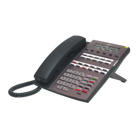
DSX Telephones Components DSX Telephones DSX Telephones 22-Button Display Telephone with Speakerphone P/Ns 1090020 (Black) and 1090025 (White) Display: 3 line x 24 character Speakerphone: Built-in, half-duplex Soft Keys: 4 Wall Mount: Built-in Feature Keys: 12 Angle Adjustment: 2 position built-in Fixed Function Keys: 12 Backlit: No Speed Dial Bin Keys: 10... -
Page 8: 34-Button Backlit Display Telephone With Full-Duplex Speakerphone
DSX Telephones 34-Button Backlit Display Telephone with Full-Duplex Speakerphone P/Ns 1090022 (Black) and 1090027 (White) Display: 3 line x 24 character Speakerphone: Built-in, full-duplex Soft Keys: 4 Wall Mount: Built-in Feature Keys: 24 Angle Adjustment: 2 position built-in Fixed Function Keys: 12 Backlit: Yes Speed Dial Bin Keys: 10 Dual LEDs: Yes... -
Page 9: Single Line Telephones
Single Line Telephones Single Line Telephones DTH-1-1 Single Line Telephone P/N 780034 (Black) Fixed Function Keys: 5 Message Waiting: Yes Speed Dial Bin Keys: 4 Ring/Message Waiting Lamp: Yes Selectable Ring Tones: Yes Wall Mount: Built-in The DTH-1-1 is a cost-effective analog single line telephone that offers 5 fixed feature keys, 4 Speed Dial bin keys and Message Waiting. -
Page 10: Dsx Cordless Telephone
DSX Cordless Telephone DSX Cordless Telephone DSX Cordless Lite II P/N 730087 Display: 2 line x 16 character Transmission: 900 MHz Narrow Band FM Status Icons: 4 Range: 350 feet (site dependent) Feature Keys: 4 Max Units Per Site: 30 (12 in close proximity) Fixed Function Keys: 8 Battery Life: Up to 7 hours talk time Channels: 30... -
Page 11: Headsets
Corded Headsets for DSX Keysets and DTR/DTH SLTs The following corded headsets are compatible with DSX keysets and the DTR/DTH single line telephones. Check with your supplier for their latest offerings. NEC / Plantronics Headsets NEC / Plantronics Amplified Headsets Plantronics Model NEC P/N Description... - Page 12 Headsets NEC / Plantronics Non-Amplified Headsets (http://www.plantronics.com) Plantronics Model NEC P/N Description Style Microphone Type Number Voice Tube Polaris StarSet In-the-Ear Noise Canceling H31N Voice Tube Polaris Mirage On-the-Ear Noise Canceling H41N Voice Tube Polaris Supra Monaural Over-the-Head Noise Canceling...
- Page 13 Headsets Accessories and Replacement Parts for Polaris Headsets NEC P/N Description Plantronics Item Number Polaris Extension Cable (10 ft.) 750655 40703-01 • For all Polaris headset models. Clothing Clip Replacement (1) 29961-01 or 750657 • For all Polaris Mirage, Tristar, and Encore headset 29961-13 models.
-
Page 14: Gn Netcom Headsets
Headsets GN Netcom Headsets GN Netcom Non-Amplified Headsets (http://www.gnnetcom.com/us/en) Model Number Description Microphone Type Style GN 2110 STD01 2100 Sound Tube Monaural Sound-Tube Over-the-Head GN 2120 NCD01 2100 Flex Monaural Noise-Canceling Over-the-Head GN 2115 STD01 2100 SoundTube Binaural Sound-Tube Over-the-Head GN 2125 NCD01 2100 Flex Binaural Noise-Canceling... -
Page 15: Headsets For Dsx Cordless Lite Ii Telephone
Headsets Headsets for DSX Cordless Lite II Telephone P/N 750637 (M175) P/N 750642 (MX150) P/N 730602 (EXP9530) The following headsets are available for the DSX Cordless Lite II Telephone: • M175 Headband Style (P/N 750637) • MX150 Earloop Style (P/N 750642) •... -
Page 16: Desi Telephone Label System
DESI Telephone Label System DESI Telephone Label System DESI Plus Labeling Software DESI Plus Labeling Software DESI Plus Labeling Software is a Windows-compatible application for printing customized key data on spe- cially designed DESI telephone labels. Use DESI Plus Labeling Software to create quick, professional cus- tom labels that can be printed on virtually any office ink jet or laser printer. -
Page 17: Desi Telephone Labels
• 34-Button Super Display Preprint (pkg 25) - P/N 1093070 • 60-Button DSS Console Preprint (pkg 25) - P/N 1093069 The following DESI labels are available for the NEC analog single line telephones. • For DTR-1-1 - Black (P/N 780400) - Metallic green (P/N 780401) -
Page 18: Dsx-40 Common Equipment
DSX-40 Common Equipment DSX-40 Common Equipment DSX-40 4x8x2 Key Telephone System with 2 Door Box Ports and Caller-ID P/N 1090001 Digital extension ports: Analog line ports: Built-in: 8 Built-in: 4 Fully expanded: 24 Total: 8 Analog extension ports: Expansion slots: Built-in: 2 Station expansion slots: 2 Fully expanded: 18... -
Page 19: Dsx-40 Pcbs
DSX-40 PCBs DSX-40 PCBs DSX-40 8-Port Digital Station (8ESIU) Card P/N 1091002 Digital station ports: 8 Installs in either the top or middle DSX-40 expansion slot. Max. cards installed: 2 (16 additional digi- Can be mixed with 8-Port Analog Station tal station ports) Cards in any combination in the top and middle expansion slots. -
Page 20: Dsx-40 4 Port (4Coiu) Line Pcb With Caller Id
DSX-40 PCBs DSX-40 4 Port (4COIU) Line PCB with Caller ID P/N 1091001 Line ports: 4 Installs only in the bottom expansion slot. Max. line cards installed: 1 (4 additional Caller ID: Built in CO line ports) Max. line ports: 8 (4 in the CO line card Message Waiting: FSK only plus 4 built-in) The 4-Port CO Line Card with Caller ID is an expansion card that provides four additional CO line ports... -
Page 21: Intramail
IntraMail IntraMail DSX IntraMail 8 x 16 P/N 1091013 Ports: 8 Storage Hours: 16 Routing Mailboxes: 16 Subscirber Mailboxes: 8 Announcement DSX-40: 34 8 Call Routing Ring Group Mailboxes: 8 UCD Group Mailboxes: 8 Total Mailboxes: DSX-40: 66 DSX IntraMail 4 x 8 P/N 1091011 Ports: 4 Storage Hours: 8... -
Page 22: Miscellaneous Cards And Optional Equipment
Miscellaneous Cards and Optional Equipment Miscellaneous Cards and Optional Equipment DSX Analog Door Box P/N 922450 DSX-40: • 2 built-in door box ports • Additional door box ports requires 2PGDAD Modules connected to Digital Station ports • The Analog Door Box is a self-contained Intercom unit typically used to monitor an entrance door. A visitor at the door can press the Door Box call button (like a door bell). -
Page 23: Dsx System Administrator (Pc Program)
Miscellaneous Cards and Optional Equipment DSX System Administrator (PC Program) Free Download Download the DSX System Administrator from http://www.necdsx.com The DSX System Administrator is a Windows -based application you can use for programming the telephone system and maintaining site databases, instead of using the conventional telephone programming. - Page 24 Miscellaneous Cards and Optional Equipment 18 ◆ Components DSX-40 Hardware Manual...
-
Page 25: Installation
Installation System Preparation System Preparation Unpacking Unpack the equipment and check it against your equipment lists. Inspect for physical damage. If you are not sure about a component’s function, review Components (page 1). Contact your Sales Representative if you have additional questions. Have the appropriate tools for the job on hand, including: a test set, a punch down tool and a digital voltmeter. -
Page 26: Installing The Main Equipment Cabinet
Installing the Main Equipment Cabinet Installing the Main Equipment Cabinet Planning the Installation Before installing the common equipment, you should mount a Main Distribution Frame (MDF) plywood back- board in a centrally located spot. A 1/2 sheet of plywood (4’ x 4’) should be adequate. Be sure to mount the backboard using suitable fasteners, taking care to adhere to standard installation practices and local codes. -
Page 27: Removing The Cover
Installing the Main Equipment Cabinet Removing the Cover You must remove the Main Equipment Cabinet cover to access the extension, line and auxiliary connections. To remove the cover: Slide the cover button to OPEN Press down and slide the cover away from the Main Equipment Cabinet. Push button to "OPEN"... -
Page 28: Hanging The Cabinet
Installing the Main Equipment Cabinet Hanging the Cabinet To hang the cabinet: Screw suitable fasteners 11 3/16” apart in a convenient location on the MDF. Be sure to leave the fasten- ers “backed out” about 3/16” from the MDF backboard. Hang the cabinet as shown. -
Page 29: Grounding The Cabinet
Grounding the Cabinet Grounding the Cabinet Attaching the Ground Wire Important You must connect your system to Electrical Service Ground. To attach the ground wire: Loosen the lug on the cabinet’s ground connection. Run a 12 AWG stranded copper wire from the ground lug to Electrical Service Ground. Firmly retighten the lug loosened in step 1 above. -
Page 30: Removing The Top Panel
Removing the Top Panel Removing the Top Panel Top Panel Removal You must remove the top panel in order to install the system battery and Expansion Cards (if required), or to replace the power supply AC input fuses. To remove the top panel: Be sure your system’s power cord is unplugged, then unscrew the 2 captive screws that secure the cabinet top panel to the base. -
Page 31: Installing Expansion Cards, The Battery, And Replacement Fuses
Installing Expansion Cards, the Battery, and Replacement Fuses Installing Expansion Cards, the Battery, and Replacement Fuses Installing Expansion Cards The DSX-40 accepts up to 3 Expansion Cards: two for stations and one for lines. The following expansion Cards are available: 8-Port Digital Station Card ((P/N 1091002) ❥... -
Page 32: Installing And Replacing The Battery
Installing Expansion Cards, the Battery, and Replacement Fuses Installing and Replacing the Battery In the event of commercial AC power failure, the battery provides short-term (14 day) backup of the Real Time Clock and station parameters. To install the battery: Insert the battery into the battery clips as shown below. -
Page 33: Power Supply Ac Input Fuses
Following Figure 7, gently push down on the battery and remove it. Replace the battery with a Sony CR2032 3-volt Lithium cell battery or equivalent. (This battery is avail- able from NEC as P/N EX0254-0040.) Verify that the Real Time Clock and station parameters data is intact. -
Page 34: Connecting Extensions And Lines
Connecting Extensions and Lines Connecting Extensions and Lines Extension and Line Connections Important Install station equipment connected to Digital Station and Analog Station Cards as on-premises extensions only. The Main Equipment Cabinet provides 8-pin mod jacks for connecting extensions and lines. Using the Installation Cable (P/N 808920) makes it easy to connect the mod jacks to standard 66M1-50 connecting blocks. - Page 35 Connecting Extensions and Lines Line Block Cable 1 Cable 2 Cable 3 Station Station Block Block Figure 8: Extension and Line Cabling Installation ◆ 29 DSX-40 Hardware Manual...
-
Page 36: Punch Down For Extensions
Connecting Extensions and Lines Punch Down for Extensions To punch down the cables for extensions: For each 66M1-50 block, punch down the Installation Cable in standard color-code order. Extensions 300-323 Shown 25-PAIR CABLE BLOCK COLOR RJ61X FUNCTION RJ61X TERM CODE To make your own cables, see Making WHT-BLU 300 T... -
Page 37: Punch Down For Lines
Connecting Extensions and Lines Punch Down for Lines To punch down the cable for lines: For each 66M1-50 block, punch down the Installation Cable in standard color-code order. Lines 1-8 25-PAIR CABLE To make your own cables, see Making BLOCK COLOR RJ61X FUNCTION... -
Page 38: Securing The Cables
Connecting Extensions and Lines Securing the Cables Securing the Ground Wires and Station Cables After you have punched down your cables, route them down the side of the cabinet and secure them with the strain relief. Figure 11: Securing the Cables Securing the AC Power Cord Snap in the provided power cord strain relief and install the cord as shown below. -
Page 39: Making Your Own Cables
Connecting Extensions and Lines Making Your Own Cables Making Your Own Installation Cables The following products should help if you make your own cables. The connector is generally referred to as a RJ45 connector wired in an RJ61X configuration. Check with your local supplier for other compa- rable products. -
Page 40: Dss Console
Connecting Extensions and Lines 25-PAIR CABLE BLOCK COLOR RJ61X FUNCTION RJ61X TERM CODE ESIU WHT-BLU 300 T BLU-WHT 300 R WHT-ORN 301 T ORN-WHT 301 R ESIU WHT-GRN 302 T GRN-WHT 302 R WHT-BRN 303 T BRN-WHT 303 R BLU-WHT WHT-BLU WHT-SLT 304 T... -
Page 41: Connecting Lines
Connecting Extensions and Lines Connecting Lines A fully expanded DSX-40 can connect up to 8 analog loop-start lines with built-in Caller ID. The basic Main Equipment Cabinet provides 4 lines. By adding a 4-Port Line Card you can connect the system to 8 lines. See Installing Expansion Cards (page 25) for more. -
Page 42: Setting Up The Telephone And Dss Console
Setting Up the Telephone and DSS Console Setting Up the Telephone and DSS Console Installing the DSX Keyset Handset and Line Cord. When installing the handset, plug the handset cord into the handset jack on the bottom of the telephone. The handset cord routes through the lower channel on the right side of the telephone base. -
Page 43: Installing The Dss Console Line Cord
Setting Up the Telephone and DSS Console Installing the DSS Console Line Cord The DSS Console connects to an available port on an 16ESIU Card, just like a keyset. You can install four maximum per system. The DSS Console line cord does not use a channel and drapes down from the tele- phone line cord jack or connects to the telephone legs. -
Page 44: Keyset And Dss Console Two Position Angle Adjustment
Setting Up the Telephone and DSS Console Keyset and DSS Console Two Position Angle Adjustment To set the low viewing angle position: Fold the legs all the way back. Figure 19: Setting the Low Viewing Angle To set the high viewing angle position: Flip up the two leg supports. -
Page 45: Removing The Faceplate
Setting Up the Telephone and DSS Console Removing the Faceplate You’ll need to remove the telephone faceplate to write on the label or install a DESI custom label. To remove the faceplate: Put your finger in the recessed area under the faceplate and lift off the faceplate. Figure 21: Removing the Telephone Faceplate Installation ◆... - Page 46 Setting Up the Telephone and DSS Console To reinstall the faceplate: Snap back into place as shown. Figure 22: Reinstalling the Telephone Faceplate 40 ◆ Installation DSX-40 Hardware Manual...
-
Page 47: Powering Up The System
Powering Up the System Powering Up the System Power Up Now that you have cabled the system, it is time to power-up. To power up the system: Make sure the system is properly grounded. Plug the AC Power Cord into the Main Equipment Cabinet Install a surge protector in the AC outlet. - Page 48 Powering Up the System Figure 23: Power Switch and AC Power Cord Power LED Figure 24: Power LED 42 ◆ Installation DSX-40 Hardware Manual...
-
Page 49: Finishing The Installation
Finishing the Installation Finishing the Installation Reinstalling the Cover Now that your cabling is complete and the system is up and running, you should reinstall the cover. To reinstall the cover: Slide the cover onto the Main Equipment Cabinet as shown. Slide the cover button to LOCK. -
Page 50: Resetting And Initializing The System
Resetting and Initializing the System Resetting and Initializing the System Resetting the System To reset the system: Important If the system’s RS-232 connection uses twisted pair cable, before resetting do one of the following: • Make sure the RS-232 cable is connected at both ends (i.e., PC and CPU). •... -
Page 51: To Initialize System
Resetting and Initializing the System Initializing the System To initialize (cold start) the system: - This erases all your stored programming and returns the system to its default settings. Turn off the system. Press and hold the Reset Switch on the Main Equipment Cabinet while turning on the system power. When the LED on the cabinet lights blue and then goes out, release the Reset Switch •... -
Page 52: Upgrading The System Software
Upgrading the System Software Upgrading the System Software Upgrade System Software To upgrade system software from a CompactFlash card: Remove the IntraMail CompactFlash card (if installed), then insert the CompactFlash card containing the system software into the Main Equipment Cabinet. - Although advisable, backing up the site programming is not required. -
Page 53: Installing Optional Equipment
Installing Optional Equipment Installing IntraMail Installing IntraMail Setting Up IntraMail for the First Time A default system (with no voice mail installed) provides the Built-In Automated Attendant. See Automated Attendant, ■ Built-In in the IntraMail section of the Software Manual for more. If you have another (external) voice mail installed, you must disconnect and unprogram it before installing IntraMail. - Page 54 Installing IntraMail To set up IntraMail: Plug the IntraMail CompactFlash card into the Main Equipment Cabinet. Reset the system. The IntraMail automatically installs. - If updating from the Built-In Automated Attendant, just rerecord your Instruction Menu Messages. Your Answer Schedule and Dial Action Table programing remain intact. - By default, the first 16 (300-315) mailboxes are active/enabled and the IntraMail Automated Atten- dant does not answer outside calls.
-
Page 55: Installing A Dsx Analog Door Box On A Built-In Door Box Port
Installing a DSX Analog Door Box on a Built-In Door Box Port Installing a DSX Analog Door Box on a Built-In Door Box Port Connecting a DSX Analog Door Box to a Built-In Door Box Port Do not connect a DSX Analog Door Box to a digital station port. The DSX Analog Door Box (P/N 922450) is a self-contained Intercom unit typically used to monitor an entrance door. - Page 56 Installing a DSX Analog Door Box on a Built-In Door Box Port 25-PAIR CABLE BLOCK COLOR RJ61X FUNCTION RJ61X TERM CODE WHT-BLU 324 T BLU-WHT 324 R WHT-ORN 325 T ORN-WHT 325 R WHT-GRN GRN-WHT WHT-BRN BRN-WHT WHT-SLT Door 1T Door 1 SLT-WHT Door 1R...
-
Page 57: Installing A Dsx Analog Door Box And 2Pgdad Module
Installing a DSX Analog Door Box and 2PGDAD Module Installing a DSX Analog Door Box and 2PGDAD Module Connecting a DSX Analog Door Box to the 2PGDAD Module The DSX Analog Door Box (P/N 922450) is a self-contained, weather-tight Intercom unit typically used to monitor an entrance door. -
Page 58: Connecting Pgdad Door Boxes And Relays
Installing a DSX Analog Door Box and 2PGDAD Module Connecting PGDAD Door Boxes and Relays To connect a Door Box: Find a suitable location for the DSX Analog Door Box. - The door box is a weather-tight unit and can be installed outdoors. Run one-pair 24 AWG station cable from the door box to the 2PGDAD Module. -
Page 59: Mounting The 2Pgdad Module And Connecting To The System
Installing a DSX Analog Door Box and 2PGDAD Module Mounting the 2PGDAD Module and Connecting to the System To mount and connect the 2PGDAD Module: Mount two suitable fasteners (such as #8 sheet metal screws) about 3 15/16” apart either horizontally (for horizontal mounting) or vertically (for vertical mounting). -
Page 60: External Paging
External Paging External Paging Installing External Paging The Main Equipment Cabinet provides an External Paging output. You connect the Main Equipment Cabinet Paging output to an audio input on a customer provided Paging system. Be sure the connected Paging equip- ment is compatible with the following page output specifications: External Paging Output Specifications Output Impedance:... -
Page 61: Music Source
Music Source Music Source Installing a Music Source Your system provides two connections for customer provided music sources. Use these music sources for Background Music and Music on Hold. Be sure the connected music sources are compatible with the follow- ing music input specifications: Music Input Specifications Input Impedance:... -
Page 62: Power Failure Telephone
Power Failure Telephone Power Failure Telephone Power Failure Cut-Through When AC power fails, the system can automatically cut through to a Power Failure Telephone connection. Analog stations 25 and 26 (extensions 324 and 325) are the permanent power failure extensions. When power fails: Analog extension 324 (station 25) automatically cuts through to line 1. -
Page 63: Wall Mounting
Wall Mounting Wall Mounting Reversing the Handset Hanger Before wall mounting your DSX telephone, you should reverse the handset hanger. The hanger holds the handset in place while the telephone is mounted on the wall. To reverse the wall-mount handset hanger: Slide out the handset hanger. -
Page 64: Wall Mounting A Keyset
Wall Mounting Wall Mounting a Keyset Wall Mounting a Keyset on a Standard Wall Plate To mount the telephone on the standard wall plate: Locate and wire a standard wall plate in a convenient location. Fold the telephone legs into the wall mount position. Make sure the handset coil cord is routed through the lower channel in the base. -
Page 65: Wall Mounting A Keyset Directly On The Wall
Wall Mounting Wall Mounting a Keyset Directly on the Wall To mount the telephone directly on the wall: Mount two suitable fasteners (such as #8 sheet metal screws) about 3 15/16” apart vertically. - Leave the heads exposed about 1/4”. Fold the telephone legs into the wall mount position. -
Page 66: Wall Mounting A Dss Console
Wall Mounting Wall Mounting a DSS Console Wall Mounting a DSS Console on a Standard Wall Plate To mount the DSS Console on the standard wall plate: Locate and wire a standard wall plate in a convenient location. Fold the DSS Console legs into the wall mount position. Fold the two leg supports down flush with the legs. -
Page 67: Wall Mounting A Dss Console Directly On The Wall
Wall Mounting Wall Mounting a DSS Console Directly on the Wall To mount the DSS Console directly on the wall: Mount two suitable fasteners (such as #8 sheet metal screws) about 3 15/16” apart vertically. - Leave the heads exposed about 1/4”. Fold the DSS Console legs into the wall mount position. -
Page 68: Keyset Self Test
Keyset Self Test Keyset Self Test Testing the Keyset Each DSX keyset has a built-in Self Test Diagnostic. Use this diagnostic to verify that each key is working, check the lamp (LED) in each key, and play back some system tones. To start the Self Test Diagnostic Unplug the keyset’s line cord. -
Page 69: Connecting A Pc To The System
Connecting a PC to the System Connecting a PC to the System Connections for PC Programming (System Administrator) and SMDR Use the USB or Ethernet port when connecting a PC locally for the System Administrator. Use the serial port only for SMDR. Ethernet (auto-sensing) CAT 5 Cable... - Page 70 Connecting a PC to the System 64 ◆ Optional Equipment DSX-40 Hardware Manual...
-
Page 71: Specifications And Parts
Specifications and Parts Specifications Specifications DSX Telephone System Specifications DSX-40 System Capacities (Page 1 of 2) Cabinets: Talk Timeslots (Intercom/line): Non-blocking Ports Lines: Digital Telephones: Analog Telephones: DSS Consoles: 4 max. per system Plugs into a digital station port DSX Analog Door Box Ports (Built-In) DSX Analog Door Boxes Max. - Page 72 Specifications (Page 2 of 2) DSX-40 System Capacities Music Inputs: Conference Circuits: 32 Conference circuits dynamically allocated, with 8 parties max per Conference. Conference circuits provided on CPU. 8-Port Digital Station Card (Expansion) 2 max. 8-Port Analog Station Card (Expansion) 2 max.
- Page 73 Specifications DSX-40 Electrical Specifications Power Supply: 120 VAC + 10% @ 50-60 Hz Output Power: 83 Watts @ 100% full load Input Current: 1.1A 132 VA Kwh: 0.132 KwH BTU: 450 Btu Grounding Requirements: 12 AWG copper wire Telephone and Line Voltages Keyset Voltages DC voltage measured at the MDF (between tip Minimum: 36 VDC...
- Page 74 Specifications Mechanical Specifications Equipment Width Depth Height Weight DSX-40 Cabinet 13 3/16” 2 3/4” 10 1/2” 3 lbs 9.5 oz Display Keyset: 7 5/8” 9 1/2” 4 3/4” 2 lb. 5.7 oz. Super Display Keyset: 7 5/8” 9 1/2” 4 3/4” 2 lb.
- Page 75 Specifications FCC Registration Information Model: DX7NA-40M Manufacturer: NEC Infrontia FCC Part 15 Registration: Class A FCC Registration Number: US:NIFKF00BDSX US:NIFMF00BDSX US:NIFPF00BDSX Industry Canada Certificate (DOC) Number: IC: 140k-DSX Reg. Status Mfrs. Port ID Network Jacks Original 02LS2 1090001 REN 0.6B...
-
Page 76: Dsx Intramail Specifications
Specifications DSX IntraMail Specifications Built-In Automated Attendant Capacities Mailboxes Routing Mailboxes: ....8 Call Routing: ..8 Announcement: . -
Page 77: Parts List
Parts List Parts List Station Equipment Description Part Number 22-Button Display Telephone with Speakerphone 1090020 (Black) 1090025 (White) 34-Button Backlit Display Telephone with Speakerphone 1090021 (Black) 1090026 (White) 34-Button Backlit Display Telephone with Full-Duplex Speaker- 1090022 (Black) phone 1090027 (White) 34-Button Backlit Super Display Telephone with Half-Duplex 1090030 (Black) Speakerphone... - Page 78 Parts List DESI Labels Description Part Number DSX Telephone Labels The following DESI labels are available for DSX telephone “replacement” applications (pkg 20 with 10 backers) DSX 22-Button Display Telephone (White) 1093086 DSX 22-Button Display Telephone (Black) 1093085 DSX 34-Button Display Telephone (White) 1093084 DSX 34-Button Display Telephone (Black) 1093083...
- Page 79 Parts List DSX Telephone Headsets Description Part Number See Headsets (page 5). Common Equipment Description Part Number DSX-40 DSX-40 Main Equipment Cabinet 1090001 Additional Common Equipment Installation Cable 808920 DSX SMDR Adaptor 1091014 (requires customer-provided 6-conductor line cord) Cards Description Part Number DSX-40 8-Port Digital Station Card (Expansion)
- Page 80 Parts List Replacement Parts Description Part Number Handset and Cord Assembly (black) 1091016 Handset and Cord Assembly (white) 1091038 22 Button Clear Plastic Cover (pkg 5) 1091018 34 Button Clear Plastic Cover (pkg 5) 1091019 34 Button Super Display Clear Plastic Cover (pkg 5) 1091020 60 Button DSS Clear Plastic Cover (pkg 5) 1091021...
- Page 81 NEC Unified Solutions, Inc. 4 Forest Parkway, Shelton, CT 06484 Tel: 800-365-1928 Fax: 203-926-5458 www.necunifiedsolutions.com Other Important Telephone Numbers Sales: ........203-926-5450 Customer Service: .
- Page 82 NEC Unified Solutions, Inc. 4 Forest Parkway, Shelton, CT 06484 TEL: 203-926-5400 FAX: 203-929-0535 www.necunifiedsolutions.com (1093097) October 26, 2006, Rev 1 Printed in U.S.A.
Need help?
Do you have a question about the DSX-40 and is the answer not in the manual?
Questions and answers