Table of Contents
Advertisement
Quick Links
TigerSwitch 10G
10 Gigabit Ethernet Switch
◆ 8 10GBASE XFP slots
◆ Non-blocking switching architecture
◆ Support for a redundant power unit
◆ Spanning Tree Protocol, RSTP, and MSTP
◆ Up to 4 LACP or static 8-port trunks
◆ Layer 2/3/4 CoS support through eight priority queues
◆ Layer 3/4 traffic priority with IP Precedence and IP DSCP
◆ Full support for VLANs with GVRP
◆ IGMP multicast filtering and snooping
◆ Support for jumbo frames up to 9 KB
◆ Manageable via console, Web, SNMP/RMON
Installation Guide
SMC8708L2
Advertisement
Table of Contents

Related Manuals for SMC Networks 8708L2


Summary of Contents for SMC Networks 8708L2
-
Page 1: Installation Guide
TigerSwitch 10G 10 Gigabit Ethernet Switch ◆ 8 10GBASE XFP slots ◆ Non-blocking switching architecture ◆ Support for a redundant power unit ◆ Spanning Tree Protocol, RSTP, and MSTP ◆ Up to 4 LACP or static 8-port trunks ◆ Layer 2/3/4 CoS support through eight priority queues ◆... - Page 3 TigerSwitch 10G Installation Guide From SMC’s Tiger line of feature-rich workgroup LAN solutions 38 Tesla Irvine, CA 92618 May 2005 Phone: (949) 679-8000 Pub. # 149100024300A...
- Page 4 Information furnished by SMC Networks, Inc. (SMC) is believed to be accurate and reliable. However, no responsibility is assumed by SMC for its use, nor for any infringements of patents or other rights of third parties which may result from its use. No license is granted by implication or otherwise under any patent or patent rights of SMC.
- Page 5 All SMC products carry a standard 90-day limited warranty from the date of purchase from SMC or its Authorized Reseller. SMC may, at its own discretion, repair or replace any product not operating as warranted with a similar or functionally equivalent product, during the applicable warranty term.
- Page 6 RIGHTS, WHICH MAY VARY FROM STATE TO STATE. NOTHING IN THIS WARRANTY SHALL BE TAKEN TO AFFECT YOUR STATUTORY RIGHTS. * SMC will provide warranty service for one year following discontinuance from the active SMC price list. Under the limited lifetime warranty, internal and external power supplies, fans, and cables are covered by a standard one-year warranty from date of purchase.
-
Page 7: Japan Vcci Class A
OMPLIANCES FCC - Class A This equipment generates, uses, and can radiate radio frequency energy and, if not installed and used in accordance with the instruction manual, may cause interference to radio communications. It has been tested and found to comply with the limits for a Class A computing device pursuant to Subpart B of Part 15 of FCC Rules, which are designed to provide reasonable protection against such interference when operated in a commercial environment. - Page 8 OMPLIANCES CE Mark Declaration of Conformance for EMI and Safety (EEC) SMC contact for these products in Europe is: SMC Networks Europe, Edificio Conata II, Calle Fructuós Gelabert 6-8, 2 08970 - Sant Joan Despí, Barcelona, Spain. This information technology equipment complies with the requirements of the Council...
- Page 9 OMPLIANCES Australia AS/NZS 3548 (1995) - Class A SMC contact for products in Australia is: SMC Communications Pty. Ltd. Suite 18, 12 Tryon Road, Lindfield NSW2070, Phone: 61-2-94160437 Fax: 61-2-94160474 Safety Compliance Warning: Fiber Optic Port Safety When using a fiber optic port, never look at the transmit laser while it is powered on.
- Page 10 OMPLIANCES • This unit operates under SELV (Safety Extra Low Voltage) conditions according to IEC 60950. The conditions are only maintained if the equipment to which it is connected also operates under SELV conditions. France and Peru only This unit cannot be powered from IT †...
- Page 11 OMPLIANCES Veuillez lire à fond l'information de la sécurité suivante avant d'installer le Switch: AVERTISSEMENT: L’installation et la dépose de ce groupe doivent être confiés à un personnel qualifié. • Ne branchez pas votre appareil sur une prise secteur (alimentation électrique) lorsqu'il n'y a pas de connexion de mise à...
- Page 12 OMPLIANCES Cordon électrique - Il doit être agréé dans le pays d’utilisation Suisse: La prise mâle d’alimentation doit respecter la norme SEV/ASE 1011. Europe La prise secteur doit être conforme aux normes CEE 7/7 (“SCHUKO”) LE cordon secteur doit porter la mention <HAR> ou <BASEC> et doit être de type HO3VVF3GO.75 (minimum).
-
Page 13: Warnings And Cautionary Messages
OMPLIANCES Warnings and Cautionary Messages Warning: This product does not contain any serviceable user parts. Warning: Installation and removal of the unit must be carried out by qualified personnel only. Warning: When connecting this device to a power outlet, connect the field ground lead on the tri-pole power plug to a valid earth ground line to prevent electrical hazards. -
Page 14: End Of Product Life Span
OMPLIANCES End of Product Life Span This product is manufactured in such a way as to allow for the recovery and disposal of all included electrical components once the product has reached the end of its life. Manufacturing Materials There are no hazardous nor ozone-depleting materials in this product. Documentation All printed documentation for this product uses biodegradable paper that originates from sustained and managed forests. -
Page 15: Table Of Contents
ABLE OF ONTENTS About the TigerSwitch 10G ..... . .1-1 Overview ........... 1-1 Switch Architecture . - Page 16 ABLE OF ONTENTS Connecting to the Console Port ....... . 3-10 Wiring Map for Serial Cable .
- Page 17 ABLE OF ONTENTS PPENDICES Troubleshooting ....... A-1 Diagnosing Switch Indicators ........A-1 Diagnosing Power Problems with the LEDs .
- Page 18 ABLES Table 1-1 Port Status LEDs ........1-5 Table 1-2 System Status LEDs .
- Page 19 IGURES Figure 1-1 Front and Rear Panels ......1-1 Figure 1-2 Port LEDs ........1-4 Figure 1-3 System LEDs .
- Page 20 IGURES...
-
Page 21: Figure 1-1 Front And Rear Panels
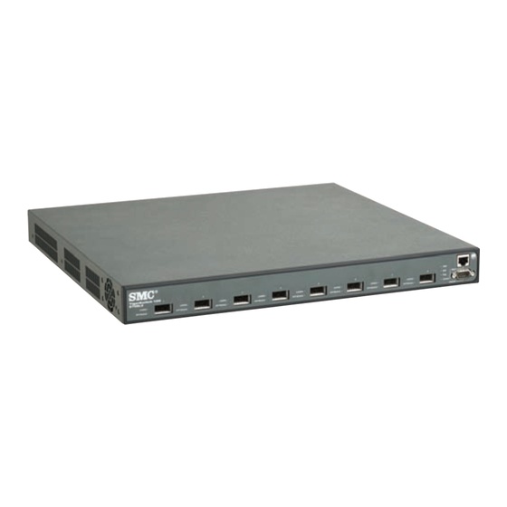
HAPTER BOUT THE IGER WITCH Overview The SMC8708L2 is a 10 Gigabit Ethernet switch with 8 10GBASE XFP slots , and 1 10/100BASE-TX RJ-45 management port. The switch also includes an SNMP-based management agent, which provides both in-band and out-of-band access for managing the switch. This switch provides a broad range of powerful features for Layer 2 switching, delivering reliability and consistent performance for your network traffic. -
Page 22: About The Tigerswitch 10G
BOUT THE IGER WITCH Switch Architecture The SMC8708L2 switch employs a wire-speed, non-blocking switching fabric. This permits simultaneous wire-speed transport of multiple packets at low latency on all ports. The switch also features full-duplex capability on all ports, which effectively doubles the bandwidth of each connection. This switch uses store-and-forward switching to ensure maximum data integrity. -
Page 23: Management Port (Rj-45)
ESCRIPTION OF ARDWARE Management Port (RJ-45) The SMC8708L2 contains one 10/100BASE-TX management port (labeled Mgmt) that operates at 10 Mbps or 100 Mbps, half or full duplex. This port is provided only for management access, and does not allow pass-through or data traffic. Note: It is also possible to manage the switch through the switch’s XFP transceiver slots. -
Page 24: Port And System Status Leds
BOUT THE IGER WITCH Port and System Status LEDs The SMC8708L2 includes a display panel for key system and port indications that simplify installation and network troubleshooting. The LEDs, which are located on the front panel for easy viewing, are described in the following figures and tables.. -
Page 25: Table 1-1 Port Status Leds
ESCRIPTION OF ARDWARE Table 1-1 Port Status LEDs Condition Status 10 Gigabit Ethernet Ports (Ports 1-8) Link/Act On/Flashing Port has established a valid 10 Gbps network Green connection. Flashing indicates activity. Yellow/Green The port has been administratively disabled. Alternate There is no valid link on the port. Green There is an XFP transceiver present in the slot. -
Page 26: Table 1-2 System Status Leds
BOUT THE IGER WITCH System LEDs Figure 1-3 System LEDs Table 1-2 System Status LEDs Condition Status On Green The unit’s internal power supply is operating normally. On Yellow The unit’s internal power supply has failed. The unit has no power connected or has failed. -
Page 27: Optional Redundant Power Unit
Alternating overheated. Optional Redundant Power Unit SMC supports an optional Redundant Power Supply (RPS), that can supply power to the switch in the event of failure of the internal power supply. Power Supply Sockets There are two power sockets on the rear panel of the switch. The standard power socket is for the AC power cord. -
Page 28: Features And Benefits
BOUT THE IGER WITCH Features and Benefits Connectivity • 8 10GBASE XFP slots for 10 Gbps Ethernet connections – supports all 10G standard XFP transceivers • One 100BASE-TX management port - Auto-negotiation enable the RJ-45 management port to automatically select the optimum communication mode (half or full duplex) if this feature is supported by the attached device;... -
Page 29: Management
EATURES AND ENEFITS Management • “At-a-glance” LEDs for easy troubleshooting • Network management agent: - Manages switch in-band or out-of-band - Supports console, Telnet, SSH, SNMP v1/v2c/v3, RMON 4 groups and web-based interface... - Page 30 BOUT THE IGER WITCH 1-10...
-
Page 31: Network Planning
HAPTER ETWORK LANNING Introduction to Switching A network switch allows simultaneous transmission of multiple packets via non-crossbar switching. This means that it can partition a network more efficiently than bridges or routers. The switch has, therefore, been recognized as one of the most important building blocks for today’s networking technology. -
Page 32: Application Examples
ETWORK LANNING Application Examples The TigerSwitch 10G is not only designed to segment your network, but also to provide a wide range of options in setting up network connections. Some typical applications are described below. Network Aggregation Plan With 8 parallel bridging ports (i.e., 8 distinct collision domains), the TigerSwitch 10G can collapse a complex network down into a single efficient bridged node, increasing overall bandwidth and throughput. -
Page 33: Remote Connections With Fiber Cable
PPLICATION XAMPLES Remote Connections with Fiber Cable Fiber optic technology allows for longer cabling than any other media type. A 10GBASE-SR (MMF) link can connect to a site up to 300 meters away, a 10GBASE-LR (SMF) link can connect to a remote site up to 10 km away and a 10GBASE-ER(SMF) link can connect to a site up to 40 km away. -
Page 34: Making Vlan Connections
ETWORK LANNING Making VLAN Connections This switch supports VLANs which can be used to organize any group of network nodes into separate broadcast domains. VLANs confine broadcast traffic to the originating group, and can eliminate broadcast storms in large networks. This provides a more secure and cleaner network environment. -
Page 35: Application Notes
PPLICATION OTES Application Notes 1. Full-duplex operation only applies to point-to-point access (such as when a switch is attached to a workstation, server or another switch). When the switch is connected to a hub, both devices must operate in half-duplex mode. 2. - Page 36 ETWORK LANNING...
-
Page 37: Installing The Switch
HAPTER NSTALLING THE WITCH Selecting a Site TigerSwitch 10G units can be mounted in a standard 19-inch equipment rack or on a flat surface. Be sure to follow the guidelines below when choosing a location. • The site should: - be at the center of all the devices you want to link and near a power outlet. -
Page 38: Ethernet Cabling
NSTALLING THE WITCH Ethernet Cabling To ensure proper operation when connecting to the management port, make sure the current cable is suitable for 10BASE-T or 100BASE-TX operation. Check the following criteria against the current installation of your network: • Cable type: Unshielded twisted pair (UTP) or shielded twisted pair (STP) cables with RJ-45 connectors;... -
Page 39: Equipment Checklist
• RS-232 console cable • This Installation Guide • Management and Installation Guide CD • SMC Warranty Registration Card—be sure to complete and return to Optional Rack-Mounting Equipment If you plan to rack-mount the switch, be sure to have the following equipment available: •... -
Page 40: Mounting
NSTALLING THE WITCH Mounting This switch can be mounted in a standard 19-inch equipment rack or on a desktop or shelf. Mounting instructions for each type of site follow. Rack Mounting Before rack mounting the switch, pay particular attention to the following factors: •... -
Page 41: Figure 3-2 Attaching The Brackets
OUNTING To rack-mount devices: 1. Attach the brackets to the device using the screws provided in the Bracket Mounting Kit. Figure 3-2 Attaching the Brackets 2. Mount the device in the rack, using four rack-mounting screws (not provided). Figure 3-3 Installing the Switch in a Rack... - Page 42 NSTALLING THE WITCH 3. If installing a single switch only, turn to “Connecting to a Power Source” at the end of this chapter. 4. If installing multiple switches, mount them in the rack, one below the other, in any order. 5.
-
Page 43: Desktop Or Shelf Mounting
OUNTING Desktop or Shelf Mounting 1. Attach the four adhesive feet to the bottom of the first switch. Figure 3-4 Attaching the Adhesive Feet 2. Set the device on a flat surface near an AC power source, making sure there are at least two inches of space on all sides for proper air flow. 3. -
Page 44: Installing An Xfp Transceiver
NSTALLING THE WITCH Installing an XFP Transceiver Figure 3-5 Installing an XFP Transceiver The XFP slots support the following XFP transceivers: • 10GBASE-SR • 10GBASE-LR • 10GBASE-ER To install an XFP transceiver, do the following: 1. Consider network and cabling requirements to select an appropriate XFP transceiver type. -
Page 45: Connecting To A Power Source
ONNECTING TO A OWER OURCE Connecting to a Power Source To connect a switch to a power source: 1. Insert the power cable plug directly into the AC socket located at the back of the switch. 100-240V~ 50-60Hz 2A Figure 3-6 Power Socket 2. -
Page 46: Connecting To The Console Port
NSTALLING THE WITCH Connecting to the Console Port The DB-9 serial port on the switch’s rear panel is used to connect to the switch for out-of-band console configuration. The command-line-driven configuration program can be accessed from a terminal or a PC running a terminal emulation program. -
Page 47: Making Network Connections
HAPTER AKING ETWORK ONNECTIONS Connecting Network Devices The TigerSwitch 10G is designed to interconnect multiple segments (or collision domains). It includes a 100BASE-TX port for management access, and 8 XFP ports for high-speed connections to your data network. XFP transceivers can be connected to any network device that supports the required 10 Gigabit Ethernet media type, such as network cards in PCs and servers, as well as to switches, routers, or remote devices. -
Page 48: Connecting Devices To The Management Port
AKING ETWORK ONNECTIONS Caution: Do not plug a phone jack connector into an RJ-45 port. This will damage the switch. Use only twisted-pair cables with RJ-45 connectors that conform to FCC standards. Connecting Devices to the Management Port 1. Attach one end of a twisted-pair cable segment to the device’s RJ-45 connector. -
Page 49: Network Wiring Connections
ONNECTING TO THE ANAGEMENT Network Wiring Connections Today, the punch-down block is an integral part of many of the newer equipment racks. It is actually part of the patch panel. Instructions for making connections in the wiring closet with this type of equipment follows. -
Page 50: Fiber Optic Xfp Devices
AKING ETWORK ONNECTIONS Fiber Optic XFP Devices A 10 Gigabit XFP transceiver (10GBASE-SR, 10GBASE-LR, or 10GBASE-ER) can be used for a backbone connection between switches, or for connecting to a high-speed server. For information on installing fiber optic XFP transceivers, refer to the following description. Each single-mode fiber port requires 9/125 micron single-mode fiber optic cable with an LC connector at both ends. -
Page 51: Figure 4-3 Making Fiber Port Connections
XFP D IBER PTIC EVICES 2. Check that the fiber terminators are clean. You can clean the cable plugs by wiping them gently with a clean tissue or cotton ball moistened with a little ethanol. Dirty fiber terminators on fiber optic cables will impair the quality of the light transmitted through the cable and lead to degraded performance on the port. -
Page 52: Connectivity Rules
AKING ETWORK ONNECTIONS Connectivity Rules 10 Gigabit Ethernet Collision Domain Table 4-1 Maximum 10GBASE-SR 10 Gigabit Ethernet Cable Length Fiber Diameter Fiber Maximum Cable Connector Bandwidth Length 62.5/125 micron 160 MHz/km 2-26 m multimode fiber (6.56-85.3 ft.) 62.5/125 micron 200 MHz/km 2-33 m multimode fiber (6.56-108.26 ft.) -
Page 53: 100 Mbps Fast Ethernet Collision Domain
ABLE ABELING AND ONNECTION ECORDS 100 Mbps Fast Ethernet Collision Domain Table 4-4 Maximum Fast Ethernet Cable Length Type Cable Type Max. Cable Length Connector 100BASE-TX Category 5 or better 100 m (328 ft) RJ-45 100-ohm UTP or STP 10 Mbps Ethernet Collision Domain Table 4-5 Maximum Ethernet Cable Length Type Cable Type... - Page 54 AKING ETWORK ONNECTIONS • Use sequential numbers for cables that originate from the same equipment. • Differentiate between racks by naming accordingly. • Label each separate piece of equipment. • Display a copy of your equipment map, including keys to all abbreviations at each equipment rack.
-
Page 55: Troubleshooting
PWR LED is Off • Check connections between the switch, the power cord, and the wall outlet. • Contact SMC Technical Support. PWR LED is Yellow • Internal power supply has failed. Contact your local dealer for assistance. Diag LED is Yellow •... -
Page 56: Diagnosing Power Problems With The Leds
ROUBLESHOOTING Diagnosing Power Problems with the LEDs The PWR and RPS LEDs work in combination to indicate power status as follows. Table A-2 Power/RPS LEDs PWR LED RPS LED Status Green Yellow Internal power functioning normally; RPS plugged in but faulty, such as a thermal or fan failure. -
Page 57: In-Band Access
CCESS In-Band Access You can access the management agent in the switch from anywhere within the attached network using Telnet, a Web browser, or other network management software tools. However, you must first configure the switch with a valid IP address, subnet mask, and default gateway. If you have trouble establishing a link to the management agent, check to see if you have a valid network connection. - Page 58 ROUBLESHOOTING...
-
Page 59: Cables
PPENDIX ABLES Twisted-Pair Cable and Pin Assignments For 10BASE-T/100BASE-TX connections to the management port, a twisted-pair cable must have two pairs of wires. Each wire pair is identified by two different colors. For example, one wire might be green and the other, green with white stripes. -
Page 60: 10Base-T/100Base-Tx Pin Assignments
ABLES 10BASE-T/100BASE-TX Pin Assignments Use unshielded twisted-pair (UTP) or shielded twisted-pair (STP) cable for RJ-45 connections: 100-ohm Category 3 or better cable for 10 Mbps connections, or 100-ohm Category 5 or better cable for 100 Mbps connections. Also be sure that the length of any twisted-pair connection does not exceed 100 meters (328 feet). -
Page 61: Crossover Wiring
WISTED ABLE AND SSIGNMENTS EIA/TIA 568B RJ-45 Wiring Standard 10/100BASE-TX Straight-through Cable White/Orange Stripe Orange White/Green Stripe End A End B Blue White/Blue Stripe Green White/Brown Stripe Brown Figure B-2 Straight-through Wiring Crossover Wiring If the twisted-pair cable is to join two ports and either both ports are labeled with an “X”... -
Page 62: Fiber Standards
ABLES Fiber Standards The current TIA (Telecommunications Industry Association) 568-A specification on optical fiber cabling consists of one recognized cable type for horizontal subsytems and two cable types for backbone subsystems. Horizontal 62.5/125 micron multimode (two fibers per outlet). Backbone 62.5/125 micron multimode or single mode. TIA 568-B will allow the use of 50/125 micron multimode optical fiber in both the horizontal and backbone in addition to the types listed above. -
Page 63: Specifications
PPENDIX PECIFICATIONS Physical Characteristics Ports 8 XFP slots, with auto-negotiation 1 10/100BASE-TX, with auto-negotiation Network Interface XFP Slots: 10GBASE-SR, 10GBASE-LR and 10GBASE-ER standard XFP transceivers Management Port: RJ-45 connector, auto MDI/X 10BASE-T: RJ-45 (100-ohm, UTP cable; Category 3 or better) 100BASE-TX: RJ-45 (100-ohm, UTP cable;... -
Page 64: Switch Features
PECIFICATIONS Size 44.0 x 41.0 x 4.3 cm (17.32 x 16.14 x 1.69 in.) Temperature Operating: 0 to 50 °C (32 to 122 °F) Storage: -40 to 70 °C (-40 to 158 °F) Humidity Operating: 5% to 95% (non-condensing) AC Input 100 to 240 V, 50-60 Hz, 2A Power Supply Internal, auto-ranging transformer: 100 to 240 VAC, 50 to 60 Hz... -
Page 65: Standards
TANDARDS Out-of-Band Management RS-232 DB-9 console port Software Loading TFTP in-band, or XModem out-of-band Standards IEEE 802.3-2002 Ethernet, Fast Ethernet, Gigabit Ethernet IEEE 802.3ae 10 Gigabit Ethernet IEEE 802.1D Spanning Tree Protocol IEEE 802.1w Rapid Spanning Tree Protocol IEEE 802.1s Multiple Spanning Tree Protocol Compliances CE Mark Emissions... -
Page 66: Warranty
PECIFICATIONS Warranty Limited Lifetime... -
Page 67: Table D-1 Tigerswitch 10G Products And Accessories
PPENDIX RDERING NFORMATION Table D-1 TigerSwitch 10G Products and Accessories Product Number Description SMC8708L2 8-port 10G managed Layer 2 switch Redundant power unit with cables, supports one SMCRPU14 device * Also available in models for Continental Europe and the UK. -
Page 68: Ordering Information
RDERING NFORMATION... -
Page 69: Glossary
LOSSARY 10BASE-T IEEE 802.3 specification for 10 Mbps Ethernet over two pairs of Category 3 or better UTP cable. 100BASE-TX IEEE 802.3u specification for 100 Mbps Fast Ethernet over two pairs of Category 5 or better UTP cable. 10GBASE-SR IEEE 802.3ae specification for 10 Gigabit Ethernet over two strands of 50/125 micron core multimode fiber cable. - Page 70 LOSSARY Bandwidth The difference between the highest and lowest frequencies available for network signals. Also synonymous with wire speed, the actual speed of the data transmission along the cable. Collision A condition in which packets transmitted over the cable interfere with each other.
- Page 71 LOSSARY Full Duplex Transmission method that allows two network devices to transmit and receive concurrently, effectively doubling the bandwidth of that link. IEEE Institute of Electrical and Electronic Engineers. IEEE 802.3 Defines carrier sense multiple access with collision detection (CSMA/CD) access method and physical layer specifications.
- Page 72 LOSSARY Light emitting diode used for monitoring a device or network condition. Local Area Network (LAN) A group of interconnected computers and support devices. Media Access Control (MAC) A portion of the networking protocol that governs access to the transmission medium, facilitating the exchange of data between network nodes.
- Page 73 LOSSARY Telecommunications Industry Association Transmission Control Protocol/Internet Protocol (TCP/IP) Protocol suite that includes TCP as the primary transport protocol, and IP as the network layer protocol. Unshielded twisted-pair cable. Virtual LAN (VLAN) A Virtual LAN is a collection of network nodes that share the same collision domain regardless of their physical location or connection point in the network.
- Page 74 LOSSARY Glossary-6...
-
Page 75: Index
NDEX Numerics EMC C-3 safety C-3 10 Gbps connectivity rules 4-6 connectivity rules 10 Mbps connectivity rules 4-7 10 Gbps 4-6 100 Mbps connectivity rules 4-7 10 Mbps 4-7 1000BASE-LR fiber cable lengths 4-6 100 Mbps 4-7 1000BASE-SR fiber cable lengths 4-6 console port 100BASE-TX pin assignments 3-10... - Page 76 NDEX web-based 1-2 mounting the switch IEEE 802.3 Ethernet 1-8 in a rack 3-4 IEEE 802.3ae 10 Gigabit Ethernet 1-8 on a desktop or shelf 3-7 IEEE 802.3ak 10 Gigabit Ethernet 1-8 multimode fiber optic cables 4-4 IEEE 802.3u Fast Ethernet 1-8 IEEE 802.3x flow control 1-3 indicators, LED 1-4 installation...
- Page 77 NDEX installing on a desktop 3-7 switch architecture 1-2 optional redundant power unit 1-7 switching RS-232 port 1-2 introduction to 2-1 rubber foot pads, attaching 3-7 method 1-2 screws for rack mounting 3-3 temperature within a rack 3-4 serial port 1-2 troubleshooting single-mode fiber optic cables 4-4 in-band access A-3...
- Page 78 NDEX Index-4...
- Page 80 81-45-224-2332; Fax 81-45-224-2331 Australia: 61-2-8875-7887; Fax 61-2-8875-7777 India: 91-22-8204437; Fax 91-22-8204443 If you are looking for further contact information, please visit www.smc.com, www.smc-europe.com, or www.smc-asia.com. 38 Tesla Model Numbers: SMC8708L2 Irvine, CA 92618 Pub. Number: 149100024300A E052005-R01 Phone: (949) 679-8000...
Need help?
Do you have a question about the 8708L2 and is the answer not in the manual?
Questions and answers