BOSE CineMate II / GS II Series Manual
- Owner's manual (122 pages) ,
- Guía de usuario (32 pages) ,
- Service manual (21 pages)
Advertisement
- 1 SPECIFICATIONS
- 2 PRODUCT DESCRIPTION
- 3 ELECTROSTATIC DISCHARGE SENSITIVE (ESDS) DEVICE HANDLING
- 4 PART LIST NOTES
- 5 MAIN PART LIST
- 6 ACCESSORY KIT PACKING LIST
- 7 PACKAGING PART LIST
- 8 SPEAKER ARRAY ASSEMBLY PART LIST
- 9 ELECTRICAL PART LIST
- 10 DISASSEMBLY PROCEDURES
- 11 TEST PROCEDURES
- 12 SAFETY INFORMATION
- 13 Documents / Resources
SPECIFICATIONS
System Specifications:
| Power Rating: | |
| US/Canada: | 100 - 240VAC, 50/60 Hz, 300W |
| Europe/UK/Aus: | 100 - 240VAC, 50/60 Hz, 300W |
| Japan: | 100 - 240VAC, 50/60 Hz, 300W |
| Dual Voltage: | 100 - 240VAC, 50/60 Hz, 300W |
| Maximum Ambient Temperature: | 45 degrees C |
| Low Frequency Cut-off (typical): Basic System: | |
| Arrays: | 180 Hz |
| Bass Module: | 45 Hz |
| GS System: | |
| Arrays: | 220 Hz |
| Bass Module: | 45 Hz |
| Woofer Impedance: | 1.5 Ohms nominal DC resistance single woofer |
| Weights: | |
| Bass Module: | 24.9 lb (11.77 kg) |
| Arrays, each: | 3.0 lb (1.40 kg) |
| IR Remote Control (batteries installed): | 0.44 lb (0.20 kg) |
| Interface Module | .65 lb (0.29 kh) |
| Total Packaged System: | 38.35 lb (17.39 kg) |
| Dimensions: | |
| Bass Module: | 14 x 8.8 x 19.2 inches (35.6 x 18.4 x 51.1 cm) |
| Bass Module internal volume: | 1205 cubic inches (19.7 liters) |
| Arrays Basic: | 7.9 x 5.3 x 3.4 inches (200 x 134 x 86 mm) |
| Arrays Premium: | 5.6 x 2.6 x 4.2 inches (142 x 65 x106 mm) |
| IR Remote Basic: | 3.9 x 1.5 x.70 inches (101.4 x 39.0 x 17.9 mm) |
| IR Remote Premium: | 9.0 x 2.6 x 1.2 inches (229.6 x 64.8 x 31.2 mm) |
| Interface Module: | 3.2 x 2.1 x 1.0 inches ( 82.5 x 53.8 x 25.4mm) |
| Distortion and Noise: | -78 dB FS THD+N, unweighted, 22-22 kHz for a 1kHz signal at FS -1dB -90 dB FS THD+N, unweighted, 22-22 kHz for a 1kHz signal at FS -10dB |
| Dynamic Range: | -90 dB FS THD+N, unweighted, 22-22 kHz for a 1 kHz signal at FS -60 dB |
| Distortion: | < 0.1% @ 0.5 W |
| Noise when Muted: | < 400 uVrms, A-weighted |
| DC Offset: | < 50 mVdc, all channels |
| Channel Balance: | +/- 1.5 dB for all volume settings |
| Channel Separation: | > 40 dB @ 1 kHz, > 30 dB @ 10 kHz, stereo mode |
| Input Impedance: | 100k Ohms nominal +/- 10% |
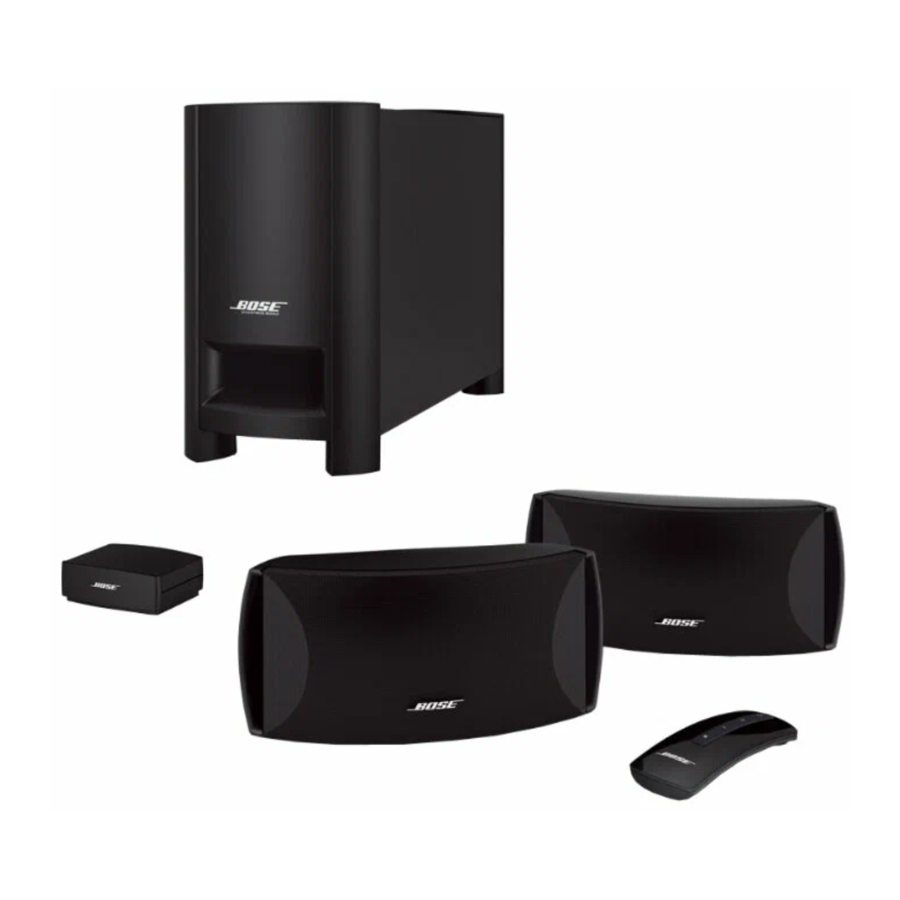
PRODUCT DESCRIPTION
CineMate® Series II is a refresh of CineMate that includes two array speakers, Acoustimass® module, interface module with digital and analog audio input and a remote control. The system offers digital audio for an impactful, spacious audio experience and a simple remote control that avoids the need for programming. It also has a fresh industrial design for its array speakers and interface module.
Two versions of the CineMate Series II are available:
- CineMate Series II - includes two standard array speakers and a basic remote.
- CineMate GS Series II - includes two gem stone array speakers and premium remote.
ELECTROSTATIC DISCHARGE SENSITIVE (ESDS) DEVICE HANDLING
This unit contains ESDS devices. We recommend the following precautions when repairing, replacing or transporting ESDS devices:
- Perform work at an electrically grounded work station.
- Wear wrist straps that connect to the station or heel straps that connect to conductive floor mats.
- Avoid touching the leads or contacts of ESDS devices or PC boards even if properly grounded. Handle boards by the edges only.
- Transport or store ESDS devices in ESD protective bags, bins, or totes. Do not insert unprotected devices into materials such as plastic, polystyrene foam, clear plastic bags, bubble wrap or plastic trays.
PART LIST NOTES
- This part is not normally available from Customer Service. Approval from the Field Service Manager is required before ordering.
- The individual parts located on the PCBs are listed in the Electrical Part List.
![warning]() This part is critical for safety purposes. Failure to use a substitute replacement with the same safety characteristics as the recommended replacement part might create shock, fire and/or other hazards.
This part is critical for safety purposes. Failure to use a substitute replacement with the same safety characteristics as the recommended replacement part might create shock, fire and/or other hazards.- This part is referenced for informational purposes only. It is not stocked as a repair part. Refer to the next higher assembly for a replacement part.
MAIN PART LIST

Figure 1. CineMate Series II System Packaging View
| Item Number | Description | Part Number | Qty. | Note |
| 1 | QUICK START GUIDE, CINEMATE® SERIES II GS | 323022-0010 | 1 | 4 |
| 2 | LITERATURE KIT, 120V, INCLUDES | - | 1 | 4 |
| BATTERY, AA, BAGGED & LABELED | 194392 | 1 | ||
| BUMPER, RECESSED, FOOT, .88" | 142839 | 4 | ||
| CARD, REGISTRATION AND WARRANTY | 262933 | 1 | ||
| GUIDE, OWNER, CINEMATE SERIES II, US/AIM GUIDE, OWNER, CINEMATE SERIES II, APAC | 323023-0010 323025-0010 | 1 | ||
| DVD SET-UP DISC, CINEMATE, NTSC | 318861 | 1 | ||
| SHEET SLIP COMPONENT AUDIO | 255805 | 1 | ||
| 3 | BAG, FOAM, 28"X24"X.03" | 322279-0010 | 1 | |
| 4 | PACKING, INSERT, EPS, BASSMOD, CINEMATE PACKING,INSERT, EPS, BASSMOD, CINEMATE GS | 319347-001 370944-0010 | 2 | |
| 5 | ACCESSORY KIT | - | ||
| 6 | ARRAY ASSY, BLK, CINEMATE ARRAY ASSY, BLK, CINEMATE, GEMSTONE | 255198-103 320560-0010 | 2 | |
| 7 | CARTON, RSC, 23.75X19.38X12.25, CINEMATE II CARTON, RSC, 23.75X19.4X12.25, CINEMATE II GS | 319345-001 320576-0001 | 1 | |
| 8 | ASSY, BASS MODULE, 120-240V, CINEMATE II ASSY, BASS MODULE, 100V, CINEMATE II | 362020-110S 362020-310S | 1 |
ACCESSORY KIT PACKING LIST

Figure 2. Accessory Kit Packing List
| Item Number | Description | Part Number | Qty. | Note |
| 1 | LINE CORD, 120V, POL, DET, BLK, 96" LINE CORD, 120V, POL, DET, BLK, 60" | 260082-001 262814-0310 | 1 | 3
|
| 2 | LINE CORD, 230V, UKS, DET, BLK, 96" LINE CORD, 230V, UKS, DET, BLK, 60" | 280138-001 280138-0310 | 1 | |
| 3 | LINE CORD, EURO, DETACHABLE, 96" LINE CORD, EURO, DETACHABLE, 60" | 148203 280135-0310 | 1 | |
| 4 | LINE CORD, 240V, AUS, DET, BLK, 96" LINE CORD, 240V, AUS, DET, BLK, 60" | 284243-001 284243-0310 | 1 | |
| 5 | LINE CORD, 100V, JP, POL, DET, BLK, 96" LINE CORD, 100V, JP, POL, DET, BLK, 60" | 260086-001 280136-0310 | 1 | |
| 6 | CABLE, RCA, 6 FT | 185931-101 | 1 | |
| 7 | ADAPTER, SCART | 266221-001 | 1 | |
| 8 | CABLE, INTERFACE MODULE, BLK | 318638-1030 or 318638-101 | 1 | |
| 9 | BUMPER, RECESSED, FOOT, .88" | 142839 | 1 | |
| 10 | FOOT, CLEAR, .312x.085, 4' | 178321-04 | ||
| 11 | REMOTE, CINEMATE II (PREMIUM) REMOTE, CINEMATE II EURO (PREMIUM) REMOTE, IR, CINEMATE, 1SR, BLK (PREMIUM) REMOTE, CINEMATE II (BASIC) | 323075-1100 323075-1200 342835-1210 323715-0010 | 1 | |
| 12 | CABLE, ARRAY, 9PIN, BLK CABLE, GS, ARRAY, 9PIN, BLK | 255123-003 269984-004 | 1 | |
| 13 | CABLE, OPTICAL, 2 METER | 288629-002 or 347411-0010 | 1 | |
| 14 | PACKING, INSERT | 267071 | 1 | |
| 15 | CARTON, D/C | 286868 | 1 |
PACKAGING PART LIST

Figure 3. Bass Module Exploded View
| Item Number | Description | Part Number | Note |
| 1 | SCREW, TT, 8-32X0.5,PAN, XREC/SQ | 289393-008 | 4 |
| 2 | ENCLOSURE, REAR, PAINTED, BLK | 318960-403 | 1 |
| 3 | SCREW, TAPP, 6-32, PAN, TORX | 279948-08 | 4 |
| 4 | SHIELD, POWER SUPPLY | 319739-0010 | 1 |
| 5 | CINEMATE II, PS, SERVICE BOM | 361720-001S | 1 |
| 6 | SCREW, TAPP, 8-11x.75, PAN, XRC/SQ | 289388-012 | 4 |
| 7 | GASKET, EMI, HEATSINK, 33MM | 276873-002 | |
| 8 | PAD, THERMAL | 323653-0010 | |
| 9 | BRACKET, POWER SUPPLY | 319738-0010 | |
| 10 | CABLE ASSY, SECONDARY PWR SUPPLY | 319494-0010 | |
| 11 | CABLE ASSY, PRIMARY, PWR SUPPLY | 319486-1020 | |
| 12 | GASKET, FOAM, .32"X12.0"X.125" | 255202 | 2 |
| 13 | BRACKET, COVER, BASS MODULE | 255179 | |
| 14 | GRILLE, VENT, AMP, BLK,KAISER | 255178-203 | |
| 15 | SCREW, TAPP, 8-11x.437, PAN, XRC/S | 289388-007 | 1 |
| 16 | SHIM, DSP PCB, SNAP HEATSINK | 319839-0010 | |
| 17 | CINEMATE II, DSP, SERVICE BOM | 318878-011S | |
| 18 | BRACKET, HEATSINK,SNAP | 304144-001 | |
| 19 | SCREW, 6-13x.5, PAN, XREC/SQ | 288374-008 | |
| 20 | BRACKET, PCB | 267182-001 | |
| 21 | CINEMATE II, IO, SERVICE BOM | 361719-001S | See Service Bulletin SB-4 |
| 22 | PAD, FOAM, .25" X.75" X.06" | 278144-001 | |
| 23 | CABLE, ARRAY, 10 CONDUCTOR | 271561-0190 | |
| 24 | CABLE, I/O, DIGITAL | 322528-001 | |
| 25 | CLIP, SPRING, KNOB | 262542 | |
| 26 | KNOB, VOLUME CONTROL, BLACK | 318324-001 |
SPEAKER ARRAY ASSEMBLY PART LIST

Figure 4. Basic Speaker Array Assembly
| Item Number | Description | Part Number | Qty. | Note |
| 1 | GRILLE, ASSEMBLY | 323211-0010 | 1 | |
| 2 | NAMEPLATE, BOSELOGO | 319457-0010 | 1 |
 Note: Only the parts listed above are replaceable.

Figure 5. Premium Speaker Array Assembly
| Item Number | Description | Part Number | Qty. | Note |
| 1 | GRILLE, ARRAY, BLK | 302256-004 | 1 | 3
|
| 2 | NAMEPLATE, BOSE®LOGO | 319457-0010 | 1 | |
| 3 | SCREW, HILO, 4-16 x.375, PAN, XREC | 288372-006 | 8 | |
| 4 | TWIDDLER™ DRIVER ASSY, 50MM | 291636-001 | 2 | 3
|
ELECTRICAL PART LIST
Bass Module DSP PCB Assembly
Resistors


Capacitors


Inductors
| Reference Designator | Description | Part Number | Note |
| L1 | 400 OHM, CHIP, 0805 | 188587-401 | 4 |
| L2 | 100uH, SMD, 20% | 256773-101 | 4 |
| L50 | 400 OHM, CHIP, 0805 | 188587-401 | 4 |
| L71 | 400 OHM, CHIP, 0805 | 188587-401 | 4 |
| L73 | 400 OHM, CHIP, 0805 | 188587-401 | 4 |
Diodes
| Reference Designator | Description | Part Number | Note |
| D2 | DIODE, SCHOTTKY, 40V, 3A, SMB | 193847-001 | 4 |
| D258 | PAD, THERMAL, COMPLIANT | 266954-001 | 4 |
| D450 | DIODE, ZEN, SOT-235.1V, 225MW, 5% | 135247-5231 | 4 |
| D4500 | DIODE, SOT-23, BAV 99 | 147239 | 4 |
| D4501 | DIODE, SOT-23, BAV 99 | 147239 | 4 |
| D4503 | DIODE, SOT-23, BAV 99 | 147239 | 4 |
| D4505 | DIODE, SOT-23, BAV 99 | 147239 | 4 |
| D4509 | DIODE, SOT-23, BAV 99 | 147239 | 4 |
| D4510 | DIODE, SOT-23, BAV 99 | 147239 | 4 |
| D4511 | DIODE, SOT-23, BAV 99 | 147239 | 4 |
| D4512 | DIODE, SOT-23, BAV 99 | 147239 | 4 |
Transistors
| Reference Designator | Description | Part Number | Note |
| Q2 | XSISTOR, MFET, P, 40V, 3.0A, SOT23 | 303215-001 | 4 |
| Q450 | XSISTOR, BPLR, N, 50V, 100mA, SOT23 | 146817 | 4 |
| Q451 | XSISTOR, BPLR, N, 50V, 100mA, SOT23 | 146817 | 4 |
| Q0452 | XSISTOR, BPLR, PNP, 500MA, SOT23 | 189290-001 | 4 |
| Q7200 | XSISTOR, BPLR, N, 50V, 100mA, SOT23 | 146817 | 4 |
Integrated Circuits
| Reference Designator | Description | Part Number | Note |
| U2 | IC, PWM, V, CNTRLLR, TPS40200 | 303218-001 | 4 |
| U3 | IC, VOLT REG, ADJ, 500MA, DPAK | 258496-001 | 4 |
| U150 | IC, PWR AMP, PSO-20, TDA8566TH | 257975 | 4 |
| U250 | IC, PWR AMP, PSO-20, TDA8566TH | 257975 | 4 |
| U350 | IC, PWR AMP, PSO-20, TDA8566TH | 257975 | 4 |
| U4000 | IC, CODEC, 24-BIT, CS4228A-KS, TS | 254192-003 | 4 |
| U4400 | IC, RCVR, DIG AUD, CS8415A, TSSOP | 267616-002 | 4 |
| U6000 | IC, RESET, 3.3V, SOT23, 5-PIN | 256123-001 | 4 |
| U6100 | IC, INVERTER, 5V, 74VCHU04 | 258464-004 | 4 |
| U7000 | IC, DSP, QFP208, ADSP21065LKS_264 | 254191-003 | 4 |
| U7200 | IC, PROM, FLASH, 4MBIT (not programmed) | 260332-002 | 4 |
| U7300 | IC, SDRAM, 64MBIT, 2MX32, 3.3V | 254182-010 | 4 |
Miscellaneous
| Reference Designator | Description | Part Number | Note |
| FB70 | BEAD, FERRITE, CHIP, 1806 | 256116-181 | 4 |
| J0005 | CONNECTOR, HEADER, RTANGLE | 190552-03 | 4 |
| J150 | CONN, HEADER, RTANG, 2.5MM, 10 POS | 145402-10 | 4 |
| J350 | CONN, THRU BOARD, TH, 4 POS | 266952-04 | 4 |
| J7100 | CONN, HEADER, 2.5MM, THRU, 16 POS | 270584-016 | 4 |
Bass Module Power Supply PCB Assembly
Resistors

Capacitors


Inductors
| Reference Designator | Description | Part Number | Note |
| L702 | 3.30mH, CHOKE, 1.2A, 250V | 321518-001 | 4,3
|
| L703 | 2.2uH, COM MODE | 187598-2R2 | |
| L704 | 2.2uH, COM MODE | 187598-2R2 | |
| L705 | 2.2uH, COM MODE | 187598-2R2 |
Diodes
| Reference Designator | Description | Part Number | Note |
| BR701 | DIODE, BRIDGE, RECT, 3A, 600V | 311102-0600 | 4 |
| D701 | DIODE, RECT, FAST, 600V, 1A | 317066-600 | 4 |
| D702 | DIODE, SWITCHING, SOD123, 1N4148W | 257662 | 4 |
| D703 | DIODE, PWR SCHOTTKY, D2PAK, 8A, 100V | 319763-100 | 4 |
| D706 | DIODE, SCHTKY, SC70, 30V, SERIES | 268381-004 | 4 |
| D707 | DIODE, SCHTKY, SC70, 30V, SERIES | 268381-004 | 4 |
| Z701 | DIODE, ZENER, SMT, IN5262, 51V | 174265-5262 | 4 |
| Z702 | DIODE, ZEN, SOT-23, 15V, 225MW, 5% | 135247-5245 | 4 |
| ZR701 | TVS, UNI-DIR, SMCJ130A, 1500W, 130V, 200A | 320498-1300 | 4 |
Transistors
| Reference Designator | Description | Part Number | Note |
| Q701 | XSISTOR, MFET, N-CH, 600V | 310519-001 | 4 |
| Q702 | XSISTOR, MFET, N-CH, 600V | 310519-001 | 4 |
| Q703 | XSISTOR, SOT-23, N, MFET, 2.5V | 252043 | 4 |
| Q704 | XSISTOR, SOT23, BPLR, N, 40V, 200mA | 146819 | 4 |
| Q705 | XSISTOR, SOT23, BPLR, N, 40V, 200mA | 146819 | 4 |
| Q706 | FET, P-CHANNEL, BSS84 | 269693 | 4 |
| Q707 | XSISTOR, TO-92AP, PWR, NPN, 500V,1.5A | 320835-002 | 4 |
| Q708 | IC, OPTOISOLATOR, CNY17F1X007 | 254120-002 | 4,3
|
| Q709 | IC, OPTOISOLATOR, CNY17F1X007 | 254120-002 | |
| Q701 | XSISTOR, MFET, N-CH, 600V | 310519-001 | 4 |
| Q702 | XSISTOR, MFET, N-CH, 600V | 310519-001 | 4 |
Integrated Circuits
| Reference Designator | Description | Part Number | Note |
| U701 | IC, PWM CONTROLLER, 80% DUTY CY | 317119-001 | 4 |
| U702 | IC, HALF-BRIDGE GATE DRIVER | 317085-001 | 4 |
| U703 | IC, VREF, SHUNT, ADJ, 1.24V, SOT23-3 | 322217-001 | 4 |
Miscellaneous
| Reference Designator | Description | Part Number | Note |
| T701 | TRANSFORMER, PWR, EER BOBBIN, 40AWG | 322253-0003 | 4,3
|
| J701 | CONN, SIDE ENTRY, W/PCB STAB | 258436 | |
| J702 | CONNECTOR, HEADER, RTANGLE | 190552-03 |
Bass Module I/O PCB Assembly
Resistors
| Reference Designator | Description | Part Number | Note |
| R600 | POTENTIOMETER, 10K, 20% | 273741-001 | 4,3
|
| R601 | 470K, 0805, 1/10W, 5% | 133626-4745 | 4 |
| R602 | 470K, 0805, 1/10W, 5% | 133626-4745 | 4 |
| R603 | 470K, 0805, 1/10W, 5% | 133626-4745 | 4 |
| VR701 | VARISTOR, bMET OX, 14mm DISC, 300V, 125J | 361431-0020 | 3
|
Capacitors
| Reference Designator | Description | Part Number | Note |
| C601 | 4.7uF, EL, 85C, 35V, 20% | 177902-4R7V | 4 |
| C602 | 2.2uF, EL, 85C, 50V, 20% | 177902-2R2H | 4 |
| C603 | 2.2uF, EL, 85C, 50V, 20% | 177902-2R2H | 4 |
| C604 | 0.1uF, FILM, X2, 275VAC, 10MM | 268166-104A | 4,3
|
| C605 | CAP, 0603, X7R, 50V, 4700pF | 191470-472 | 4 |
Miscellaneous
| Reference Designator | Description | Part Number | Note |
| F600 | FUSE, TIME LAG, 4A, 250V | 310538-4000A | 4,3
|
| J600 | CONN, HEADER, PC MNT, KEYED | 271899-010 | |
| J601 | CONN, D-SUB, R/A, 9 PIN, SOCKET | 285805-09 | |
| J602 | CONN, DUAL ROW, 16-P, 0.1mm, SHRT LATCH | 323689-016S | |
| J603 | CONN, D-SUB, R/A, FEMALE, 9 PIN | 285818-001 | |
| J604 | CONN, HEADER, LOCKING, TOP, KEYED | 271897-002 | |
| J605 | AC CONN, SINGLE PIECE LEADS | 301125-001 |
DISASSEMBLY PROCEDURES
Bass Module Procedures
- Rear Enclosure Removal
- Place the bass module on its side. Using a phillips-head screwdriver, remove the four screws that secure the rear enclosure to the bass module cabinet.

- Lift the rear enclosure partially off of the bass module.
- Unplug the three cables connecting to the I/O board.

- Place the bass module on its side. Using a phillips-head screwdriver, remove the four screws that secure the rear enclosure to the bass module cabinet.
- I/O PCB Removal
- Remove the two screws securing the I/O PCB and lift the board away from the rear enclosure.
![]()
- Remove the two screws securing the I/O PCB and lift the board away from the rear enclosure.
- Power Supply PCB Removal
- Remove the four screws securing the power supply PCB and shield, then lift the shield away from the bass module.

- Remove the two cables connected to the power supply board.

- Remove the four screws securing the power supply PCB and shield, then lift the shield away from the bass module.
- DSP PCB Removal
- Release the bracket holding the DSP board by placing a flat blade screw driver into the gap shown in the picture to the right.

- Once the bracket is released, the DSP can be pulled away from the heat sink.

- Release the bracket holding the DSP board by placing a flat blade screw driver into the gap shown in the picture to the right.


Standard Satellite Array Procedures
Notes:
- The standard satellite arrays are non repairable. These arrays have cloth grilles, and are larger than the GemstoneTM arrays.
- The only parts that can be replaced on the standard arrays are the grille and the nameplate.
- Grille Removal
- Place the satellite array on its back on a bench. Use your thumb to press down on the array grille at the center of the curve near the side. Use a flat tip screwdriver to pry the end of the grille off of the array enclosure. Repeat this at the other end of the grille.

![warning]() Re-Assembly Note: Align the grille so that the Bose® logo is facing the same direction as the arrows on the front of the array enclosure. Press the grille in place. It should latch to the enclosure at each end.
Re-Assembly Note: Align the grille so that the Bose® logo is facing the same direction as the arrows on the front of the array enclosure. Press the grille in place. It should latch to the enclosure at each end.
- Place the satellite array on its back on a bench. Use your thumb to press down on the array grille at the center of the curve near the side. Use a flat tip screwdriver to pry the end of the grille off of the array enclosure. Repeat this at the other end of the grille.

Gemstone Satellite Array Procedures
- Grille Removal
- Using a scribe or small flat-tip screw-driver, grasp the edge of the grille. Gently pull the grille away from the enclosure.

- Using a scribe or small flat-tip screw-driver, grasp the edge of the grille. Gently pull the grille away from the enclosure.
- Driver Removal
- Perform procedure 1.
- Remove the four screws that secure the driver to the enclosure. Lift the driver out of the enclosure and cut the wires as close to the driver as possible.


Functional Test Setup
Equipment required:
- CineMate® Series II Interface Module cable
- CineMate Series II IR Remote control
- CineMate Speaker Array Cable
- CineMate Speaker Array, Qty. 2
- CineMate Line cord
- Digital Multimeter (DMM)
- Audio Signal Generator
- CD Player with Optical Output
- S/PDIF to Optical Converter
- Bass Module Air Leak Test
- Set up the system for normal operation, connect the speaker cable, speaker arrays, interface cable and power cord.
- Point the CineMate remote control at the interface module and press power. The green LED should turn on.
- Press and hold the volume down button for 10 Seconds to confirm volume is set to zero.
- Apply a 750 mV, 45 Hz signal to the left and right analog inputs on the CineMate interface cable.
- Press and hold the volume + buttonf or 20 seconds. This will ensure the volume is adjusted to Maximum.
- Listen for air leaks around all cabinet seams and joints to a minimum of five seconds. Verify that no leaks can be heard at a distance greater than or equal to 1 foot from the bass module cabinet.
- System Frequency Sweep Test
- Set up the system for normal operation, connect the speaker cable, speaker arrays, interface cable and power cord.
- Point the CineMate remote control at the interface module and press power. The green LED should turn on.
- Press and hold the volume down button for 10 Seconds to confirm volume is set to zero.
- Apply a 750 mV, 10 Hz signal to the left and right analog inputs on the CineMate interface cable.
- Press and hold the volume + button for 20 seconds. This will ensure the volume is adjusted to Maximum.
- Sweep the input frequency from 10 Hz to 500 Hz while listening for any extraneous noises such as buzzes, rattles, ticks, port noise or distortion.
- Optical Digital Audio Test
- Connect a CD player with digital optical connection.
- Power on the CineMate system and select the digital optical input.
- Play a familiar audio CD and adjust audio volume to a comfortable listening level.
- Listen for distortion, pops, ticks and confirm audio quality is correct.
TEST PROCEDURES
Satellite Array Procedures
Notes:
- The satellite arrays are non-repairable.
- The grills can be replaced using the disassembly/assembly procedures.
- Each satellite array contains two identical drivers that are wired independently.
- You must test each of them separately
- DC Resistance Test
- Using a DMM, measure the DC resistance of each of the array drivers. Each should measure 3.2 Ohms + 10%.
- Phase Test
- Remove the array grille using array disassembly procedure 1.
- Observing polarity, apply a +6 Vdc level to one driver on the array input connector.
- Observe the driver under test. When the DC level is applied, the driver should move outward. If it does, the driver is wired correctly. If not, it is wired incorrectly. Repeat steps 2.2 and 2.3 for the other driver in the array.
- Air Leak Test
- Apply a 180 Hz, 3 V rms signal to one of the Twiddler drivers in the satellite array for 5 seconds minimum.
- Listen for air leaks around all enclosure seams, joints and the input connector. Air leaks will be heard as a hissing or sputtering noise. Repair any air leaks. All repairs must be hidden.
- Listen for air leaks around all enclosure seams, joints and the input connector. Air leaks will be heard as a hissing or sputtering noise. Repair any air leaks. All repairs must be hidden.
- Listen for any rubbing or ticking noise from the Twiddler. Replace any driver that is defective.
![warning]() Note: There is a normal suspension noise. To distinguish between a rub or tick and suspension noise, displace the cone slightly with your finger. If the rubbing can be made to go away or get worse, then it is a rub or tick. If the noise stays the same, it is suspension noise.
Note: There is a normal suspension noise. To distinguish between a rub or tick and suspension noise, displace the cone slightly with your finger. If the rubbing can be made to go away or get worse, then it is a rub or tick. If the noise stays the same, it is suspension noise. - Repeat steps 3.1 to 3.3 for the other driver in the array.
- Frequency Sweep Test
- Jumper both of the drivers in a single array together. Both center pins of the array connector are negative (-). The two outer pins are the positive (+) pins.
- Apply a 100 Hz, 3.0 V rms signal to both of the array drivers.
- Slowly sweep the signal generator from100 Hz to 2.0 kHz. Listen for any extraneous noises such as buzzes, rattles, ticks, port noise or distortion. Replace any array with an extraneous noise that can be heard at a distance greater than 1 foot (0.3m).
SPECIFICATIONS AND FEATURES SUBJECT TO CHANGE WITHOUT NOTICE
SAFETY INFORMATION
- Parts that have special safety characteristics are identified by the
![warning]() symbol on schematics or by special notes on the parts list. Use only replacement parts that have critical characteristics recommended by the manufacturer.
symbol on schematics or by special notes on the parts list. Use only replacement parts that have critical characteristics recommended by the manufacturer. - Make leakage current or resistance measurements to determine that exposed parts are acceptably insulated from the supply circuit before returning the unit to the customer. Use the following checks to perform these measurements:
- Leakage Current Hot Check-With the unit completely reassembled, plug the AC line cord directly into a 120V AC outlet. (Do not use an isolation transformer during this test.) Use a leakage current tester or a metering system that complies with American National Standards Institute (ANSI) C101.1 "Leakage Current for Appliances" and Underwriters Laboratories (UL) 60065 / IEC 60056 paragraph 9.1.1. With the unit AC switch first in the ON position and then in OFF position, measure from a known earth ground (metal water pipe, conduit, etc.) to all exposed metal parts of the unit (antennas, handle bracket, metal cabinet, screw heads, metallic overlays, control shafts, etc.), especially any exposed metal parts that offer an electrical return path to the chassis. Any current measured must not exceed 0.5 milliamp. Reverse the unit power cord plug in the outlet and repeat test. ANY MEASUREMENTS NOT WITHIN THE LIMITS SPECIFIED HEREIN INDICATE A POTENTIAL SHOCK HAZARD THAT MUST BE ELIMINATED BEFORE RETURNING THE UNIT TO THE CUSTOMER.
- Insulation Resistance Test Cold Check-(1) Unplug the power supply and connect a jumper wire between the two prongs of the plug. (2) Turn on the power switch of the unit. (3) Measure the resistance with an ohmmeter between the jumpered AC plug and each exposed metallic cabinet part on the unit. When testing 3 wire products, the resistance measured to the product enclosure should be between 2 and infinite MOhms. Also, the resistance measured to exposed input/output connectors should be between 4 and infinite MOhms. When testing 2 wire products, the resistance measured to exposed input/output connectors should be between 4 and infinite MOhms. If it is not within the limits specified, there is the possibility of a shock hazard, and the unit must be repaired and rechecked before it is returned to the customer.

The CineMate® Series II contains no user-serviceable parts. To prevent warranty infractions, refer servicing to warranty service stations or factory service.

Danger of explosion if remote battery is incorrectly replaced. Replace with only Duracell, Eveready, Energizer, Maxell or Toshiba CR2032 or DL2032 3-volt lithium battery.
Documents / Resources
References
Download manual
Here you can download full pdf version of manual, it may contain additional safety instructions, warranty information, FCC rules, etc.
Advertisement


Need help?
Do you have a question about the CineMate II Series and is the answer not in the manual?
Questions and answers