Bose Lifestyle 28, Lifestyle 35 Installation Guide
- Operating manual (72 pages) ,
- Troubleshooting manual (32 pages) ,
- Installation manual (113 pages)
Advertisement
- 1 Introduction
-
2
System Installation
- 2.1 Getting started
- 2.2 Cables and accessories
- 2.3 Placing your speakers
- 2.4 Placing your media center
- 2.5 Connecting the speakers to the Acoustimass module
- 2.6 Connecting the Acoustimass module to the media center
- 2.7 Connecting the antennas
- 2.8 Connecting your TV to the system
- 2.9 Connecting your VCR to the system
- 2.10 Connecting your cable/satellite box to the system
- 2.11 Installing the TV on/off detector
- 2.12 Connecting the system to power
- 2.13 Installing the remote control batteries
- 2.14 Turning off the internal speakers in your TV
- 2.15 Checking your installation
- 3 Reference
- 4 Important Safety Instructions
- 5 Safrty Information
- 6 Contacting customer service
- 7 Documents / Resources
Introduction
Region numbers
Region numbers are assigned to DVD players and discs according to where they are sold. Look for the region number marked on the carton or on the bottom of the media center.
For example, a region 1 DVD player should be marked like this:

Your system can play only DVD discs marked with the same region number.
Types of discs you can play
The DVD player in your system ca play the following types of discs:
| Video DVDs |  |
| Audio CDs |  |
| CD-Rs or CD-R/Ws | |
| MP3 CDs |
System Installation
Getting started
After unpacking your new system, save all packing materials. The original packing materials provide the safest way to transport your system if necessary. If any part of your system is missing or appears damaged, contact your authorized Bose® dealer immediately, or contact Bose directly.
The instructions in this section tell you how to connect your system as shown in Figure 1. For alternate system connections, see the Reference section.
 Note: You should not connect the video output of your Lifestyle® system to a VCR, since playing copy-protected DVDs may result in poor picture quality.

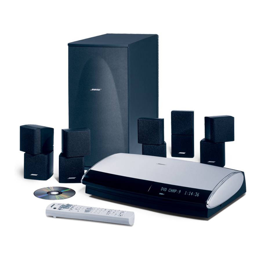
Figure 1 System connection diagram System connection diagram
Cables and accessories
The following accessories are included with your system.

Figure 2 Accessories included with your system
Placing your speakers
When you place your speakers according to the guidelines below, a combination of reflected and direct sound provides the audio atmosphere of a home theater. You may experiment with the placement and orientation of the speakers to produce the sound most pleasing to you.

Choose a stable and level surface for your speakers. Vibration can cause the speakers to move, particularly on smooth surfaces like marble, glass, or highly polished wood If you are placing the center speaker on top of the television, use the smaller of the two sets of rubber feet provided. You may obtain additional rubber feet (part number 178327) by contacting Bose® Customer Service.
Note: Do not place a cube speaker on its side, as this diminishes performance.
Left and right front speaker placement
To best match sound and picture, the left and right front speakers should be placed at the edge of the TV picture (Figure 3).

Figure 3 Recommended speaker locations
- Place the speakers up to 3 feet (1 m) from the edge of the TV screen and line them up with the center Of the TV screen.
Bose recommends ä maximum distance of 3 feet (1 m) from the edge of the TV screen so that the sound does not become too separated from the picture. You may wish to vary this distance based on room conditions and personal preference. The front cables allow the cube speakers to be placed up to 20 feet (6.1 m) from the Acoustimass® module. - Direct one cube of each speaker array forward. Direct the other cube toward the wall or in a different direction to create reflected sound. See the illustration of reflected sound patterns in Figure 4.

Figure 4 Speaker placement and reflection rays

Center speaker placement
The sound from the center speaker should appear to come directly from the center of the picture. The center speaker cable allows up to 20 feet (6.1 m) distance from the Acoustimase module.
- Place the center speaker directly above or below the center of the TV screen, or at the closest convenient location.
- Align the speaker with the front of the screen (not pushed to the back of the TV).
- Direct each of the cubes slightly away from center, to create a wider area of direct sound.
Note: If you put the speakers in a bookcase unit, be sure to place them at the front edge of the shelf. Placing speakers in an enclosed space can change the tonal quality of the sound.
Surround speaker placement
The rear surround speakers create an area of sound around the listener. Place them in the back half of your room. Direct the cubes slightly away from the listeners so that you cannot pinpoint the exact location of the sound source. The surround cables allow up to 50 feet (15.2 m) distance from the Acoustimass module.
- Place the speakers at ear height (when seated) or higher, if possible.
- Adjust the rear surround speakers to direct the sound to the front and back of the listener.
Acoustimass® module placement
Follow these guidelines to select a location for the Acoustimass module:
Note: To avoid interference with the TV picture, place the Acoustimass module at least 18 inches (45 cm) from the TV
- Place the Acoustimass module along the same wall as the TV, or close to the same end of the room as the front speakers (see Figure 4).
- Place the Acoustimass module so that the grille with the Bose® emblem faces into the room or along the wall to avoid blocking the sound output or creating too much bass.
- For best bass performance, DO NOT place the Acoustimass module at equal distances from any two walls or from a wall and the ceiling.
- For convenience, you may want to slide the Acoustimass module under a table or behind a sofa. However, DO NOT allow furniture or drapes to block the ventilation openings of the module.
- Place the Acoustimass module within reach of the audio input cable, speaker cables, and an AC power (mains) outlet.
- Place the Acoustimass module on the floor on its long edge or lay it down on its largest side. DO NOT stand it on either end. See figures below:
BEST

For proper ventilation, place it on the long edge, with connectors facing the floor.
ALTERNATE

Place it on its largest side. This may allow you to slide it under a chair or sofa.
DO NOT

stand the module on the back end. This surface is slightly curved and the slightly curved and the module may tip over.
DO NOT

stand the module on the front grille. The weight of the module can damage the grille.
Figure 5 Right and wrong placements for the Acoustimass module
- Once you have selected a position for the module, place the four self-adhesive rubber feet near the corners of the bottom surface. The rubber feet provide increased stability and protection from scratches.
DO NOT cover the ventilation openings of the Acoustimass module, The slots on the end provide ventilation for the built-in electronic circuitry, and should not be blocked.
The magnetic field from the Acoustimass module is not an immediate risk to your video tapes, audio tapes, and other magnetic media. However, you should not store tapes directly on or near the Acoustimass module.
Placing your media center
Select a location for the media center, keeping in mind the following guidelines:
- Do not block the front of the media center. Make sure you allow enough room to lift up the front cover and open the CD tray of the CD/DVD player. Also, position the media center so that you can clearly view the display window to the right of the CD tray cover. See Figure 6 for a description of the front of the media center.
- Place the media center close enough to other sound sources (W and VCR) to allow for easy cable connections. If you need additional audio and/or video cables to connect all of your components, see your dealer or call Bose® Customer Service.
- Place the media center within 30 feet (9.1 m) of the Acoustimass® module (the length of the audio input cable).

Figure 6 Front features of media center
Connecting the speakers to the Acoustimass module
Note: Before you start making system connections, make sure that the media center, the Acoustimass module, and any additional equipment are not connected to AC power.
The five dual-cube speakers that come with your system will either have a two-wire cable connector (Figure 7)

Figure 7 A two-wire connection type speaker
or a plug-in cable connector (Figure 8).

Figure 8 A plug-in cable type speaker
Identify your type of speaker and then follow the corresponding instructions.
Note: To lengthen the speaker cables, use heavy-duty RCA extension cables, or splice in 18-gauge or thicker cord (connecting + to + and - to -). To purchase extension cables, see your dealer or electronics store, or call Bose Customer Service.
Making a two-wire speaker connection
In a two-wire connection, the wire marked with a red collar is positive (+) and the plain one is negative. These wires match the positive (red) and negative (black) terminals on the back of each speaker.
Note: The surround speaker cables are joined together for your convenience, providing an easy-to-use cable for connecting the surround speakers. To run the cables in different directions from the Acoustimass module, simply pull apart the cables as needed.
- Match the correct cable to the corresponding speaker location. Front speaker cables have blue connectors at one end, with L, R, or C molded into the connectors. The red collars on the + wire are labeled Left, Right, and Center. Surround speaker cables have orange connectors at one end, with L or R molded into the connectors. The red collars on the + wire are labeled Left and Right.
- Connect the wire end of one speaker cable to the terminals on the rear of the matching speaker. Press the terminal tab on the back of the speaker and insert the marked wire (+) into the red terminal and the plain wire (-) into the black terminal. Release the tab to secure the wire. Repeat this step for each of the five speakers.
- Connect each cable to the corresponding jack on the Acoustimass module (Figure 9). Plug the blue connectors into the matching left front, center, and right front jacks. Plug the orange connectors into the matching left surround and right surround jacks.

Figure 9 Speaker connections to the Acoustimass module

Making a plug-in cable speaker connection
- Match the correct cable to the corresponding speaker location. Front speaker cables have blue RCA connectors at one end, with L, R, or C molded into both the RCA connectors and the speaker connectors at the other end. Surround speaker cables have orange RCA connectors at one end, with L or R molded into both the RCA connectors and the speaker connectors at the other end.
- Insert the speaker connector of each cable fully into the jack on the rear of each of the five speakers. Match the ridge of the connector to the notch at the top of the jack.
- Connect each cable to the corresponding jack on the Acoustimass® module (Figure 9). Plug the blue connectors into the matching left front, center, and right front jacks. Plug the orange connectors into the matching left surround and right surround jacks.
Connecting the Acoustimass® module to the media center
Connect the Acoustimass module to the media center with the audio input cable (Figure 10).

Figure 10 Acoustimass connection to media center
Note: Be sure that each connector is fully inserted into each jack.
- Plug the small black multi-pin connector (flat side facing up) into the SPEAKER ZONES Jack labeled "1 " on the back of the media center.
- Insert the telephone-style RJ-45 connector on the other end of the audio input cable into the AUDIO INPUT jack on the Acoustimass module. Align the connector at the angle shown in Figure 10. When properly connected, it should lock in place.
Note: Refer to "Setting up a second listening zone" for information on connecting a second zone.
Do not place strain on the audio input cable, especially on the connection to the Acoustimass module. Placing excessive strain on the cable may cause damage to the cable connection at the Acoustimass module. When disconnecting the cable from the Acoustimass module, be sure to press the tab on the connector.
Connecting the antennas
The rear panel of the media center provides connections for AM and FM antennas (Figure 11). Be sure to unwind the wires of each antenna to ensure the best reception.

Figure 11 Connections for the AM and FM antennas
Note: Outdoor antennas may be used. To install an outdoor antenna, consult a qualified installer. Follow all safety instructions supplied with the antenna.
Connecting an FM antenna
Plug the connector on the FM dipole antenna lead into the FM antenna jack. Spread out the antenna arms. Change the orientation of the antenna arms to get optimum FM reception. Place the antenna as far from the media center and other external equipment as possible.
Connecting the AM antenna
Note: To mount the AM antenna on a wall, follow the instructions enclosed with the antenna.
- Plug the connector on the AM antenna lead into the AM antenna jack.
- Stand the loop antenna on the base, following the instructions enclosed with the AM antenna.
- Move the AM loop antenna as far as possible (at least 20 inches [50 cm]) from the media center, and at least 4 feet (1.2 m) from the Acoustimasse module. Experiment with the orientation of the loop for optimum AM reception.
Connecting to a cable radio provider
Some cable TV providers make FM radio signals available through the cable service to your home, This connection is made to the external FM jack on the back panel of the media center. To connect to this service, contact your cable TV provider for assistance.
Note: Make sure that the cable radio installation includes a signal splitter so that only the FM radio band, not the cable TV band, is received by the media center. If necessary, contact a qualified installer.
Connecting your TV to the system
The media center provides audio and video connections for your TV. See Figure 12.

Figure 12 Media center-to-TV video and audio connections
Making audio connections
Using the supplied stereo audio cable, connect the left (L) and right (R) audio outputs on the rear panel of your TV to the L and R TV audio inputs on the rear panel of the media center.
Making video connections
Using the supplied video cable (with yellow connectors), connect the COMPOSITE video output on the rear panel of the media center to the VIDEO INPUT on the rear panel of your TV.
Note: If you prefer to use S-video or component video connections, see the following information on alternate video connections.
Alternate video connections
Before using either of these alternate video connections, you will need to change the video output setting in your system. See your operating guide for instructions.
S-VIDEO
The S-VIDEO OUTPUT provides a higher quality picture on your "TV than the COMPOSITE VIDEO OUTPUT. This jack is provided on many TVs. To make this connection you will need to use the S-video cable which is included with your system.
Component video
Some newer televisions are equipped with component video input jacks. Component video consists of three separate video signals (Y, Pb, and Pr) which deliver a very high quality picture to your TV.
To make component video connections, you will need video-grade cables for the Y, Pb, and Pr jacks and the Bose® component video adapter (Figure 13).

Figure 13 Component video adapter connections
This adapter plugs into the S-VIDEO and COMPOSITE outputs. Your system will send the correct signals to these jacks when you change the video output setting to YPbPr. See your Lifestyle® 28/35 Operating Guide for instructions on how to change system settings.
Note: Component video jacks are often color-coded and it is essential that you match the color-coded connections with the cables.
Connecting your VCR to the system
Note: If your VCR did not come with the stereo audio and video cables required to connect it to your Lifestyle® system, contact your local electronics store or authorized Bose dealer:
Note: The type of video connection used with your TV must match the type of connection used with your VCR If you connected your TV to the COMPOSITE VIDEO OUTPUT connect your VCR output to the COMPOSITE VIDEO INPUT If you connected your TV to the S-VIDEO OUTPUT, connect your VCR to the S-V/DEO INPUT If your VCR does not have an S-V/DEO output, you may be able to connect your VCR composite video output directly to your TV.
The rear panel of the media center provides audio and video connections for your VCR.
- Using the supplied stereo audio cable, connect the left (L) and right (R) audio outputs on the rear panel of your VCR to the L and R VCR audio inputs on the rear panel of the media center.
- Using the supplied video cable, connect the COMPOSITE video input on the rear panel of the media center to the VIDEO OUT on the rear panel of your VCR.

Figure 14 Media center-to-VCR video and audio connections

Connecting your cable/satellite box to the system
Note: If your cable/satellite box did not come with the stereo audio and video cables required to connect it to your Lifestyle® system, contact your local electronics store or authorized Bose dealer.
Note: The type of video connection used with your TV and VCR must match the type of connection used with your cable/satellite box. If you connected your TV to the COMPOSITE VIDEO OUTPUT connect your cable/satellite box output to the COMPOSITE VIDEO INPUT. If you connected your TV to the S- VIDEO OUTPUT, connect your cable/satellite box to the S-VIDEO INPUT.
The rear panel of the media center provides audio and video connections for your cable/satellite box.
- Using a stereo audio cable, connect the left (L) and right (R) audio outputs (if available) on the rear panel of your cable/satellite box to the L and R AUX audio inputs on the rear panel of the media center.
- Using a video cable, connect the VIDEO OUT on the rear panel of your cable/satellite box to the COMPOSITE video input on the rear panel of your VCR. You may also connect the VIDEO OUT from your cable/satellite box directly to your media center's COMPOSITE video input (as shown in Figure 15) if your VCR is not using it.

Figure 15 Media center-to-cable/satellite box video and audio connections (if VCR not used)

Installing the TV on/off detector
The TV on/off detector senses whether your TV is on or off and enables the media center to automatically switch your TV on and off as needed. If this device is not installed, you will need to turn your TV on and off using the remote control that came with your TV.
- Attach the TV on/off detector to the back of your using the mounting strip included with your new system (Figure 16).

Figure 16 TV on/off detector installed on your TV
- Plug the connector on the end of the cord into the TV SENSOR jack on the back of the media center.

Note: This device will work correctly only after your system is programmed to operate your brand of TV. See "Programming your remote control to control your TV" in your operating guide.
Note: If you have a projection TV, mount this device on the lower back portion of the enclosure opposite the connector panel.
Note: This device will not work with LCD and plasma TVs.
Connecting the system to power
- Plug the small end of the Acoustimass® power cord into the AC power jack on the connector panel of the Acoustimass module (Figure 17). Plug the other end of the power cord into an AC (mains) outlet.

Figure 17 Power connection to Acoustimass module
- Plug the small round connector of the media center power supply cable into the DC POWER jack on the back of the media center (Figure 18). Plug one end of the power supply line cord into the power supply, and plug the other end into an AC (mains) outlet.
 Figure 18 Power connection to media center
- Turn the Acoustimass POWER switch to on ( I ).

 Figure 18 Power connection to media center
Installing the remote control batteries
Slide the battery compartment cover off of the back of the remote. Find the polarity markings (+ and —) inside the compartment and install the four batteries accordingly. Slide the cover back on the remote and snap it closed.
Replace the batteries when the remote control stops operating or its range seems reduced. Alkaline batteries are recommended.
Note: Do not change the settings of the factory-preset miniature switches. See your Operating Guide for information on how to prevent conflicts with other Lifestyle® music systems.

Figure 19 Remote control battery installation
Turning off the internal speakers in your TV
When you listen to TV sound through your Lifestyle® system, the speakers in your TV should not be on. Use the on-screen menus in your TV to select "INTERNAL SPEAKERS: OFF" (the exact on-screen message may be different for different TVs). You can also lower the volume of your TV to its lowest setting. Refer to your TV owner's guide for detailed instructions.
Checking your installation
Before you reach for your operating guide, Bose® recommends that you take the time to play the Lifestyle® Home Entertainment System Setup DVD. The setup DVD provides an audiovisual guide for checking your system connections.
To get started:
- Turn your television on.
- Lift up the media center front cover and press Open/CIose
![]() .
. - Insert the DVD into the tray (label side up) and press Open/CIose
![]() again.
again. - Press CD/DVD
![]() on the remote.
on the remote. - If the DVD disc does not start to play automatically, press Play
![]() .
.
 .
. again.
 on the remote.
 .
.Reference
Using alternate system connections
The following describes alternate ways to connect your VCR and TV to your Lifestyle® home entertainment system.
To play VCR audio (not TV audio) through your system
Connect the VCR audio outputs to the TV inputs of the media center as in Figure 1, but do not connect the TV audio outputs.
In this configuration, your VCR audio is played through your system, but the TV audio is played directly from the TV. You must have the VCR turned on to hear any surround sound effects.

Figure 19 Diagram of a typical system
To play TV audio through your system with VCR audio fed to the TV
Connect the VCR audio outputs to the audio inputs of the TV. Connect the TV audio outputs to the TV inputs on the media center.
In this configuration, the VCR can be off, but the Lifestyle® system TV source must always be selected.

Figure 20 Diagram of a typical system
Setting up a second listening zone
Your Lifestyle® home entertainment system can direct sound from one or two sound sources (such as CD, AM/FM tuner, TAPE, or AUX) to two different listening zones at the same time.
What is a zone?
Each listening area, whether a room or a group of rooms (including outdoor areas), is called a zone. Your primary listening area is set up as zone 1.
What do I need for setting up a second zone?
- A Bose® powered speaker system that is compatible with your home entertainment system. An existing stereo system can also be connected (special adapter required).
- The appropriate Lifestyle® system cable to connect the zone 2 speaker system to the SPEAKER ZONES 2 connector on the rear panel of the media center.
- A second Lifestyle® system remote control to operate the zone 2 sound.
See your dealer or contact Bose for information on obtaining additional powered speakers, remote controls, cables, and adapters for connecting additional equipment.
How do I set up a speaker system in a second zone?
- Set up a speaker system in zone 2.
- Connect the audio input cable from the zone 2 system to the SPEAKER ZONE 2 output on the rear panel of the media center.
- When power is connected and you are ready to set up your second remote control, see "Setting up a second listening zone" in your Lifestyle® system operating guide.

Figure 21 Media center-to-Zone 2 connections

Note: For zone 2, use only cables that have a mini-DIN connector marked 'FIX". Cables marked "VAR ' should not be used.
Connecting external equipment
Other equipment can be connected to your system using standard RCA audio cables. Be sure to match the red connector to the R (right) channel and the white (or black) connector to the L (left) channel. A Y adapter can be used to connect mono sources. The appropriate cables are available at most electronic stores.
Connecting record/playback equipment
The rear panel of the media center provides input (TAPE) and output (RECORD) connections for a cassette tape deck.

Figure 22 Record/playback connections
Connecting other playback equipment
Other playback components such as an audio CD changer can be connected to the AUX inputs on the rear panel of the media center.

Figure 23 AUX input connections
Using digital audio connections
If your TV, VCR, tape deck, or AUX component has electrical digital audio connections, you may connect them to the media center using the corresponding DIGITAL connector. You will need a 750 cable with RCA connectors (such as a video cable).
Using optical digital audio connections
If your TV, VCR, tape deck, or AUX component has an optical digital audio connection, you may connect it to the media center using the OPTICAL INPUT/OUTPUT connectors. You will need an optical digital cable to make this connection.
Note: Before you can listen to a source through the OPTICAL input, you need to assign the OPTICAL connection to TV, VCR, TAPE or AUX. See your operating guide for instructions on using the system settings menus.
Technical information
Media center power pack rating: USA/Canada: 120V, 60 Hz, 66W
Speaker system power rating: USA/Canada: 120\/, 50/60 Hz, 350W
Media center inputs:
- TAPE: 2Vrms, maximum
- AUX: 2Vrms, maximum
- VCR: 2Vrms, maximum
- TV: 2Vrms, maximum
- DIGITAL: SPDIF (1 each for TV, VCR, TAPE, and AUX)
- COMPOSITE VIDEO: NTSC or PAL format 1 vp-p with sync 75 Q
- S-VIDEO: Luminance IVp-p, Chrominance 0.3Vp p
- Component video: NTSC or PAL IVp-p with sync on Y
- OPTICAL INPUT: SPDIF digital, mapped to input
- FM antenna: 75 Q
- AM antenna: 12pH
- TV SENSOR: NTSC/PAUHDTV/480p compatible
Media center outputs:
- SPEAKER ZONES 1 and 2: Variable audio, user selectable
- RECORD L and R: Fixed audio
- RECORD DIGITAL: SPDIF
- OPTICAL OUTPUT: SPDIF, -15 to -21 dbm
- COMPOSITE VIDEO: NTSC or PAL IVp-p with sync 75 Q
- S-VIDEO: Luminance IVp-p, Chrominance 0.3Vp-p
Remote control range: 65 ft (20 m)
Dimensions/Weights:
| Media Center: | 15.8" W x 11.0" D x 3.5" H (40.1 cm x 27.9 cm x 8.9 cm) | 8.2 1b (3.7 kg) |
| Cube speakers: (2-wjre conn.) | 3.1" W x 4.0" D x 6.2" H (7.8 cm x 10.2 cm x 15.7 cm) | 2.4 1b (1.1 kg) |
| Cube speakers: (plug-in conn.) | 2.2" W x 3.2" D x 4.4" H (5.6 cm x 8.1 cm x 11.2 cm) | 1.0 1b (0.5 kg) |
| Acoustimass® module: | 8.0" W x 24.5" D x 16.0" H (20.3 cm x 62.2 cm x 40.6 cm) | 35.9 Eb (16,3 kg) |
Finish:
Media center: Aluminum
Cube speakers: Polymer painted
Acoustimass module: Vinyl veneer, Poiymer
Important Safety Instructions
- Read these instructions - for all components before using this product.
- Keep these instructions - for future reference.
- Heed all warnings — on the product and in the owner's guide.
- Follow all instructions.
- Do not use this apparatus near water or moisture - Do not use this product near a bathtub, washbowl, kitchen sink, laundry tub, in a wet basement, near a swimming pool, or anywhere else that water or moisture are present.
- Clean only with a dry cloth - and as directed by Bose® Corporation. Unplug this product from the wall outlet before cleaning.
- Do not block any ventilation openings. Install in accordance with the manufacturer's instructions — To ensure reliable operation of the product and to protect it from overheating, put the product in a position and location that will not interfere with its proper ventilation. For example, do not place the product on a bed, sofa, or similar surface that may block the ventilation openings. Do not put it in a built-in system, such as a bookcase or a cabinet that may keep air from flowing through its ventilation openings.
- Do not install near any heat sources, such as radiators, heat registers, stoves or other apparatus (including amplifiers) that produce heat.
- Do not defeat the safety purpose of the polarized or grounding-type plug. A polarized plug has two blades with one wider than the other. A grounding-type plug has two blades and a third grounding prong. The wider blade or third prong are provided for your safety. If the provided plug does not fit in your outlet, consult an electrician for replacement of the obsolete outlet.
- Protect the power cord from being walked on or pinched, particularly at plugs, convenience receptacles, and the point where they exit from the apparatus.
- Only use attachments/accessories specified by the manufacturer.
![]()
Use only with the cart, stand, tripod, bracket or table specified by the manufacturer or sold with the apparatus. When a cart is used, use caution when moving the cart/apparatus combination to avoid injury from tip-over.- Unplug this apparatus during lightning storms or when unused for long periods of time - to prevent damage to this product.
- Refer all servicing to qualified service personnel. Servicing is required when the apparatus has been damaged in any way: such as power supply cord or plug is damaged; liquid has been spilled or objects have fallen into the apparatus; the apparatus has been exposed to rain or moisture, does not operate normally, or has been dropped - Do not attempt to service this product yourself. Opening or removing covers may expose you to dangerous voltages or other hazards. Please call Bose to be referred to an authorized service center near you.
- To prevent risk of fire or electric shock, avoid overloading wall outlets, extension cords, or integral convenience receptacles.
- Do not let objects or liquids enter the product — as they may touch dangerous voltage points or short-out parts that could result in a fire or electric shock.
- See product enclosure bottom for safety related markings.

- Use proper power sources - Plug the product into a proper power source, as described in the operating instructions or as marked on the product.
- Avoid power lines — Use extreme care when installing an outside antenna system to keep from touching power lines or circuits, as contact with them may be fatal. Do not install external antennas near overhead power lines or other electric light or power circuits, nor where an antenna can fall into such circuits or power lines.
- Ground all outdoor antennas - If an external antenna or cable system is connected to this product, be sure the antenna or cable system is grounded. This will provide some protection against voltage surges and built-up static charges.
Section 810 of the National Electrical Code ANSI/ NFPA No.70 provides information with respect to proper grounding of the mast and supporting structure, grounding of the lead-in wire to an antenna discharge unit, size of grounding conductors, location of antenna-discharge unit, connection to grounding electrodes, and requirements for the ground electrode. Refer to the antenna grounding illustration below.
Note: Unauthorized modification of the reciewer or radio remote control could void the user's authority to operate this equipment.
This product complies with the Canadian ICES-003 Class B specifications.
Antenna grounding
Example of antenna grounding as per National Electrical code, ANSI/NFPA 70.

Note to CATV system installer
This reminder is provided to call the CATV system installer's attention to Article 820-40 of the NEC (of USA) that provides guidelines for proper grounding. In particular, it specifies that the cable ground shall be connected to the grounding system of the building, as close to the point of cable entry as is practical.
Safrty Information

To reduce the risk of fire or electric shock, do not expose the system to rain or moisture.

RISK OF ELECTRIC SHOCK
DO NOT OPEN
TO REDUCE THE RISK OF ELECTRIC SHOCK, DO NOT REMOVE COVER (OR BACK). NO USER-SERVICABLE PARTS INSIDE. REFER SERVICING TO QUALIFIED PERSONNEL.
These CAUTION marks may be located on the back and bottom panels of your Lifestyle® media center and on the bottom panel of your Acoustimass® module:
 The lightning flash with arrowhead symbol, within an equilateral triangle, is intended to alert the user to the presence of uninsulated dangerous voltage within the system enclosure that may be of sufficient magnitude to constitute a risk of electric shock.
The exclamation point within an equilateral triangle, as marked on the system, is intended to alert the user to the presence of important operating and maintenance instructions in this owner's guide.
To prevent electric shock, match wide blade of plug to wide slot, insert fully.
Class 1 laser product
The DVD player contained within the media center is classified as a Class 1 Laser Product according to EN 60825-1: 1 994 + Al 1. The Class 1 Laser Product label is located on the bottom of the media center.
Use of controls or adjustments or performance of procedures other than those specified herein may result in hazardous radiation exposure. The compact disc player should not be adjusted or repaired by anyone except properly qualified service personnel.
Class B emissions limits
This Class B digital apparatus meets all requirements of the Canadian Interference-Causing Equipment Regulations.
Additional safety information
See the additional instructions on the Important Safety Information sheet enclosed in the shipping carton.
Please read this owner's guide
Please take the time to follow this owner's guide carefully. It will help you set up and operate your system properly, and enjoy all of its advanced features. Save your owner's guide for future reference.
For your records
For your records Serial numbers are located on the bottom of the media center and the bottom panel of the Acoustimass module. Serial numbers are located on the bottom of the media center and the bottom panel of the Acoustimass module.
Contacting customer service
USA
1-800-367- 4008
Phone hours— ET (Eastem Time):
Weekdays 8:30 a.rn. to 8 p.m.
Saturdays to 3 p.m.
Canada
1-800-465-2673
Phone hours— ET (Eastem Time):
Weekdays 9 a.rn. to 5 p.m..
United Kingdom
TEL 0870-741-4500
FAX 0870-741-4545
World Wide Web
www.bose.com
Documents / Resources
References
Download manual
Here you can download full pdf version of manual, it may contain additional safety instructions, warranty information, FCC rules, etc.
Advertisement


Need help?
Do you have a question about the Lifestyle 28 and is the answer not in the manual?
Questions and answers