Thermador Professional Series, PH30HWS, PH36HWS, PH48HWS Manual
- Recipes (148 pages) ,
- Use and care manual (104 pages) ,
- Installation manual (76 pages)
Advertisement
- 1 Before you begin
- 2 Installation requirements and clearances
- 3 Preparing the installation
-
4
Installation
- 4.1 Installation height
- 4.2 Cutout for vertical discharge
- 4.3 Cutout for horizontal discharge
- 4.4 Wall mount installation
- 4.5 Cabinet installation
- 4.6 Blower motor installation
- 4.7 Make-up air damper relay switch (optional)
- 4.8 Built-in remote control accessory (optional)
- 4.9 Installing a duct cover (optional)
- 4.10 Installing the grease trays and filters
- 4.11 Heat lamps (PHxxGWS only)
- 5 Installer checklist
- 6 Customer Service
- 7 IMPORTANT SAFETY INSTRUCTIONS
- 8 Documents / Resources
Before you begin
Read these instructions before you begin to install your appliance.
Important notes

Improper installation of gas appliances and ventilation hoods can create a risk for carbon monoxide which can be harmful. To reduce the risk of carbon monoxide poisoning, ensure the gas appliance is properly installed according to the manufacturer's instructions, as well as ensuring the hood is vented to the outside for proper exhausting of gases or fumes.
- Gas cooking appliances release carbon monoxide that can be harmful or fatal if inhaled. To reduce the risk of fire and to properly exhaust air, the exhaust gases extracted by the hood should be vented outside of the building only.
- Consult local building codes for requirements or restrictions related to installation of ventilation products in recirculation mode.
- Hood installation height above a cooktop, rangetop or range can vary. To obtain the necessary installation height above a cooktop, rangetop or range, consult the appliance's installation manual or combination matrix.
 NOTICE:
The hood can be damaged from excessive heat if a range or rangetop is operated with multiple burners at high settings under a hood that is installed at minimum clearances and is turned off.
Distance from cooking surface
The installation height above a cooktop, rangetop or range is recommended as a minimum height of 30" (762 mm); however, it is necessary to follow the cooking appliance manufacturer's installation instructions for proper hood height.
Refer to local building codes for the latest requirements or restrictions when installing ventilation products in recirculation mode.
Parts included
After unpacking all the parts, check for any damage in transit and for completeness of delivery.
- Metal transition with backdraft damper
- Baffle filters
- Grease trays
- Filter spacers
- Blower adapter
- Heat lamps (PHxxGWS models only)
- Wood support bracket used as hood mounting bracket (needed for installation - DO NOT THROW AWAY
- Literature packet with fastener assortment Hardware provided is for mounting through standard thickness drywall or plaster into wood studs. Installers are responsible to provide hardware for other types of mounting situations.
Tools and parts needed
Prepare these tools and accessories before you start to install your appliance.
- Blower (Refer to the Ventilation Planning Guide for compatible blowers)
- Ducting as needed (Refer to table Equivalent duct lengths for commonly used transitions. )
- Aluminum tape (DO NOT use insulating or cloth duct tape)
- ½" (13 mm) conduit if required Follow local codes
- 1" (25.4 mm) strain relief
- Cross head screwdriver
- T20 star bit screwdriver
- ¹¹⁄₃₂" nut driver or socket and ratchet
- Drill with ³⁄₁₆" (4.76 mm) drill bit
- Circular saw or jigsaw
- Wire stripper
- Measuring tape
- Pencil
- Level
- Safety gloves

DO NOT throw away any packaging until appliance is fully installed.
Optional accessories available for separate purchase Refer to www.thermador.com for details.
| Accessory | Description |
| EXTNCB25W | 25 ft. remote and in-line blower extension cable |
| EXTNSET4 | 25 ft. remote and in-line blower extension cable adapter kit |
| RFPLT600P | Roof plate for use with
|
| RFPLT1000P | Roof plate for use with
|
| REMCPW | Remote control panel |
Installation requirements and clearances
Appliance dimensions
PHxxGWS
This model series is 27" (686 mm) in depth and features brushed stainless-steel canopy with LED lights and heat lamps.

Note: The transition is centered horizontally.
The hood needs to be centered over the cooking surface for best performance.
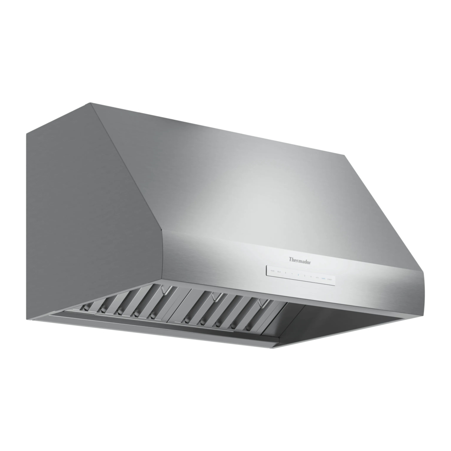
PHxxHWS
This model series is 24" (610 mm) in depth and features brushed stainless-steel canopy with LED lights.

Note: The transition is centered horizontally.
The hood needs to be centered over the cooking surface for best performance.
Clearances
Hood installation height above a cooktop, rangetop or range can vary. To obtain the necessary installation height above a cooktop, rangetop or range, consult the appliance's installation manual.

X Electrical zone
*Follow cooking appliance manufacturer's recommendations.
Hood width
- The hood width should be no less than the width of the cooking surface. For proper performance, the housing must cover the entire cooking surface.
- For proper performance, the hood must be centered horizontally above the cooking surface. Where space is not restricted, a wider hood can be used to increase capture area.
Distance from cooking surface
- Hood installation height above a cooktop, rangetop or range can vary.
- The installation height ranges from a minimum height of 30'' (762 mm) to a suggested maximum height of 40'' (1,016 mm). However, it is necessary to follow the cooking appliance manufacturer's installation instructions for proper hood height.
NOTICE:
The hood could incur some damage from heat if a Thermador Professional® Series range or rangetop is operated with multiple burners at high settings under a hood that is installed at minimum clearances while the hood is turned off.
Unit weight
- This vent hood is heavy. Adequate structure and support must be provided in all types of installations.
- When calculating the load for the housing support system, be sure to consider the weight of the ventilation unit.
| Description | Weight |
| PH30HWS | 62 lbs (29 kg) |
| PH36HWS | 70 lbs (32 kg) |
| PH48HWS | 85 lbs (39 kg) |
| PH36GWS | 75 lbs (34 kg) |
| PH42GWS | 84 lbs (38 kg) |
| PH48GWS | 90 lbs (41 kg) |
| PH54GWS | 96 lbs (44 kg) |
| PH60GWS | 103 lbs (47 kg) |
| Integral blower model VTN1DZ Only with PH30HWS | 8 lbs (3.6 kg) |
| Integral blower model VTN2FZ | 19 lbs (8.6 kg) |
| Integral blower model VTN2DA | 14 lbs (6.3 kg) |
NOTICE:
The supplied weights address only the ventilation unit and blower. The installer must account for weight of any materials of construction when calculating the total dead weight load of installation, including but not limited to: wall, tile, mortar, plaster, brick, finishes, partitions, and other similarly incorporated architectural and structural items. It is the responsibility of the owner and the installer to determine if additional requirements and/or standards apply to specific installations.
Support structure
- Due to the weight of the hood, make sure the wood mounting bracket is attached to all available wall studs.
- Wall framing should be made of 2"x 4" lumber at minimum. Proper structural support is required to accommodate the weight of the hood.
Venting
- The hood requires the ducting to be vented to the exterior of the building.
Electrical requirements
This appliance must be properly grounded.
- The appliance requires a 120V AC, 60Hz. 15A branch circuit.
- The VTN2FZ and VTN2DA blowers in conjunction with a PHxxGWS require a 20A circuit breaker.
- The appliance should only be connected to a dedicated circuit (with ground) that has been installed according to relevant regulations.
- When connected to a GFCI-protected supply, Thermador Professional® Series hoods are suitable for use in damp locations that are protected from outside weather conditions and not subject to saturation with water and other liquids, but can be subject to moderate degrees of moisture, such as an outdoor covered patio or lanai area. Refer to local codes, NEC/CEC, and/or the Authority Having Jurisdiction (AHJ) for additional information.
- Check your local building codes for proper method of installation. This appliance should be installed in accordance with applicable local codes or, in the absence of local codes, with the National Electrical Code, NFPA 70 or the Canadian Electric Code, CSA C22.1-02.
- The 25 ft. remote and in-line blower extension cable accessory (EXTNCB25W) will only work for distances up to 25 ft. The accessory cable must be purchased separately. DO NOT use more than one blower extension cable per installation.
- Electrical data: Refer to the rating plate for product data, including the model and serial number.
- If provided with an electrical plug, connect the hood to a receptacle that complies with current regulations and placed in an accessible position. Where an electrical plug is not provided (direct connection to electrical network) or the plug will not be in an accessible position after installation, place an approved bipolar switch in accessible position that provides full disconnection under overvoltage category III conditions, in accordance with local wiring rules.
Preparing the installation
Ductwork preparation
- The exhaust air is discharged upwards through a duct or directly through the outside wall into the open.
- The appliance can be mounted on the wall only with a vertical discharge.
- Proper performance is dependent upon proper ducting. Local building codes may require the use of make-up air systems when using ducted ventilation systems greater than specified cubic feet per minute (CFM) of air.
- The specified CFM varies from locale to locale. It is the responsibility of the owner and the installer to determine if additional requirements and/or standards apply to specific installations.
- DO NOT USE FLEXIBLE DUCT; it creates back pressure/air turbulence and reduces performance.
- Always install a metal vent cover where the ductwork exits the house.
- The appliance must be vented to the outside of the building only.
- COLD WEATHER installations should have an additional backdraft damper installed to minimize backward cold air flow and a nonmetallic thermal break to minimize conduction of outside temperatures as part of the ductwork. The damper should be on the cold air side of the thermal break. The break should be as close as possible to where the ducting enters the heated portion of the house.
- MAKE-UP AIR: Local building codes may require the use of make-up air systems when using ducted ventilation systems greater than specified CFM of air movement. The specified CFM varies from locale to locale. It is the responsibility of the owner and the installer to determine if additional requirements and/ or standards apply to specific installations.
- To reduce risk of fire and to properly exhaust air, be sure to duct air outside. Do not vent exhaust air in spaces with walls or ceilings or into attics, crawl spaces or garages.
- Thermador recommends not exceeding 50 ft (15.24 m) equivalent of duct.
- Keep duct runs as short and straight as possible. Elbows and transitions fittings reduce air flow efficiency. Back to back elbows and "S" turns give very poor delivery and are not recommended.
- A short, straight length of duct at the inlet of a remote blower gives the best delivery.
- Hoods are supplied with a 10" (254 mm) transition. A locally supplied transition is required for other sizes.
- Use the "Equivalent duct lengths for commonly used transitions" table to compute permissible lengths for duct runs to outdoors.
Equivalent duct lengths for commonly used transitions

Note: These commonly used installation parts can be purchased at a local hardware store. Thermador does not manufacture all these parts.
Common ducting configurations

- Varies
- Integral blower
- Remote blower
- Inline blower
- Back-draft damper on transition
Note: The figure does not represent all configurations or installation methods. The image is to be used as a guide ONLY.
Choosing the correct blower
All blower models are sold separately. It is recommended to use only Thermador blowers with Thermador Pro ventilation hoods. See the "Ventilation Planning Guide" for recommended blowers. Contact Customer Service for additional options. → "Customer Service".
You can purchase integral, in-line and remote blowers through your authorized Thermador dealer. For local dealer information, visit the "Find a Dealer" section at www.thermador.com.
The blower performance options vary in cubic feet per minute (CFM). The required performance is dictated by the cooking surface, the volume of air that needs to be moved and the length of the duct run. For long duct runs with multiple turns and bends, consider using a more powerful blower. For the most efficient air-flow exhaust, use a straight run or as few elbows as possible. → "Ductwork preparation"
Blower options
| Description | SKU |
| Remote blower Mounted to roof or external wall | VTR1FZ VTR2FZ |
| In-line blower Mounted between kitchen and external wall | VTI1FZ VTI2FZ |
| Integrated blower Mounted inside the hood | VTN1DZ (PH30HWS only) VTN2FZ VTN2DA |
25 ft. remote and in-line blower extension cable
The accessory cable must be purchased separately. DO NOT use more than one extension cable per installation.
| Description | SKU |
| 25 ft. remote and in-line blower extension cable Available to connect the hood to the inline and remote blowers for distances up to 25 ft. | EXTNCB25W |
Hood transition
Discharge direction
The hood can be mounted on a wall or suspended from a cabinet. Both vertical and horizontal discharge are possible with either mounting method.
Vertical discharge transition
The hood is shipped ready for vertical discharge.
The transition supplied with the hood connects to standard 10" round duct. The figure shows the transition connected for vertical discharge.

Changing to horizontal discharge transition
- The transition supplied with the hood connects to standard 10" round duct. The figure shows the transition connected for horizontal discharge.

- To change to horizontal discharge, move the discharge cover to the top of the hood. Use a ⅜'' nut driver to remove the four (4) ⅜" hex nuts from the plate.


Attaching the hood transition
Your hood is supplied with a 10" (254 mm) round transition. A locally supplied transition is required for other sizes.
- The supplied transition mounts to the top or rear of the hood, depending on the discharge direction. A minimum height clearance of 8⅜" (212 mm) is needed above the hood for transition mounting.

- Depending on direction of discharge, align the mounting holes at the base of the transition over the mounting holes of the ½" (13 mm) flange located at the top or rear of the hood.
- Fasten the transition to the hood using four (4) ¼" (6 mm) sheet metal screws included with the hood.
![information]() Note: Make sure the screws do not hinder the damper operation.
Note: Make sure the screws do not hinder the damper operation. - Seal the connection between transition and hood with aluminum tape. DO NOT use duct tape. Ensure that the connection is completely sealed.

- Remove the tape that is holding the damper closed.


Installation
Before installing, turn power OFF at the service panel.
▶ Lock service panel to prevent power from being turned ON accidentally.
Installation height
Installation height above cooking surface:
- Minimum height: 30" (762 mm)
- Suggested maximum height: 40" (1,016 mm)
NOTICE:
Always follow the cooking appliance manufacturer's installation instructions for proper installation height.
Cutout for vertical discharge
Vertical discharge installations require a cutout in the ceiling to accommodate 10" (254 mm) duct and ⅝" (16 mm) diameter clearance hole for ½" (12.7 mm) conduit to the junction box.

X = Conduit zone
| Hood size | A |
| 30" (762 mm) | 15" (381 mm) |
| 36" (914 mm) | 18" (457 mm) |
| 42" (1067 mm) | 21" (533 mm) |
| 48" (1219 mm) | 24" (610 mm) |
| 54" (1372 mm) | 27" (686 mm) |
| 60" (1524 mm) | 30" (762 mm) |
Cutout for horizontal discharge
Horizontal discharge requires a wall cutout to provide clearance for the transition. The location of the cutout is determined by the hood installation height.

B Back wall
C Hood mounting heights: 30"– 40" (762 –1016) from cooking surface
X 21" (533 mm)
| Hood size | A |
| 30" (762 mm) | 15" (381 mm) |
| 36" (914 mm) | 18" (457 mm) |
| 42" (1067 mm) | 21" (533 mm) |
| 48" (1219 mm) | 24" (610 mm) |
| 54" (1372 mm) | 27" (686 mm) |
| 60" (1524 mm) | 30" (762 mm) |
Wall mount installation
Back wall preparation
The hood needs to be centered over the cooking surface for best performance.
Note: The hardware provided is for mounting through standard thickness drywall or plaster into wood studs. Installers are responsible to provide hardware for other types of mounting situations.
Hanging the wood support bracket
- Turn power OFF at the service panel. Lock service panel to prevent power from being turned ON.
- Determine the hood installation height.
- Draw a horizontal line at a distance above the cooking surface equal to the hood installation height plus 16½" (419 mm). This line is the mounting location of the wood bracket shipped with the hood.

*Follow cooking appliance manufacturer's recommendations.

- Find the centerline of the hood. Draw a vertical line along this centerline up to the horizontal line drawn in the previous step.
- The hood is mounted to the wall using the wood bracket shipped with the hood. Remove the wood bracket located at the back side of the hood by removing the two shipping screws. Discard the shipping screws.
- Mark the centerline of the wood bracket.
- Locate a stud on both sides of the hood centerline to use for mounting the wood bracket.
- Align the top of the wood bracket along the horizontal line drawn earlier. Align the centerlines of the bracket and cooktop.
- Drill a 3" (76 mm) deep ¼" (6 mm) tap hole through the wood bracket, wall, and into the stud.
- Remove the bracket and place it on a sturdy surface. Make the hole larger by drilling a ⁵⁄₁₆" (8 mm) hole through the wood bracket. Use a countersink bit to make a hole large enough to countersink the screw heads to prevent interference with the hood.
- Use two (2), 3" (76 mm) screws to attach the wood bracket to the wall.
- On the wood bracket, mark the locations used to hang the hood as shown.


| Hood size | A |
| 30" (762 mm) | 13" (330 mm) |
| 36" (914 mm) | 16" (406 mm) |
| 42" (1067 mm) | 19" (483 mm) |
| 48" (1219 mm) | 22" (559 mm) |
| 54" (1372 mm) | 25" (635 mm) |
| 60" (1524 mm) | 28" (711 mm) |
- Drill a ³⁄₁₆" (4.8 mm) tap hole through the wood bracket and wall. These ⅝" (16 mm) screws do not need to go into the studs.
- Use two (2) 1½" (38 mm) screws to secure the wood bracket leaving ¼" (6 mm) of each screw exposed for hanging the hood.
Mounting the hood to the wood bracket
- Install the transition. → "Hood transition",
Fasten the transition with (2) ⅜" sheet metal screws (supplied) and aluminum tape. Follow all applicable codes. - Using two people to lift, rest the hood on the screws in the wood bracket. Use the keyholes (F). Make sure the wood bracket fits into the recess on the back of the hood.


- Tighten the screws in the keyholes. Check hood levelness and adjust if necessary.
- From inside the hood, drive ⅝" (16 mm) screws through holes in hood into wood support bracket (J).
- Connect additional ducting.
Cabinet installation
The hood can be installed under a cabinet by supporting the hood from the top.
Note: The cabinet must be structurally joined to the wall studs to support the weight of the hood. Check the structural integrity of the cabinet and wall before proceeding.
- The figure shows the (4) screw holes (K) used for mounting the hood to the bottom of the cabinet. Make sure both knockouts have been removed.


| Hood size | A |
| 30" (762 mm) | 29" (737 mm) |
| 36" (914 mm) | 35" (889 mm) |
| 42" (1067 mm) | 41" (1041 mm) |
| 48" (1219 mm) | 47" (1194 mm) |
| 54" (1372 mm) | 53" (1346 mm) |
| 60" (1524 mm) | 59" (1499 mm) |
- In the base of the cabinet, drill ⅛" (3 mm) tap holes spaced as indicated by dimension A.
- Screw in four (4) 1" (25 mm) screws (provided) leaving ¼" (6 mm) exposed to hang the hood on.
- For vertical discharge, create clearance holes for passage of the transition and conduit as shown in → "Cutout for vertical discharge".
- For horizontal discharge, follow the instructions form horizontal discharge transition for the geometry of the cutout required for clearance of the transition. → "Cutout for horizontal discharge
- Hang the hood from screws and tighten securely.
- From inside of hood, insert the screws supplied. Drill through holes, use the ⅝" (16 mm) screws supplied, (1) on each side and (4) along the front, into bottom of the cabinet. See screw holes labeled "L" in figure.
Blower motor installation

To reduce the risk of fire and electric shock, install this range hood only with the blowers listed in the Ventilation Planning Guide.
Note: Cutting the plug of the blower will void the warranty or eligibility for return or exchange.
Installing the integral blower
Integral blower models are integrated into the hood at the time of installation. Integral blowers should be installed after the hood is mounted to the wall. For complete installation instructions, see the instructions supplied with the blower unit.
Note: Blower and hood image views vary depending on model.
- Thread one (1) 4m flange nut (included with the hood) half-way down each of the two weld studs indicated.


- Slide the blower mounting plate behind the nuts on the weld studs.


- Install two (2) 4m flange nuts (included with hood) to the top weld studs and tighten.
- Tighten the two (2) nuts from step 1 to fully secure the blower to the hood.
- Connect the blower's plug connector to the connector present inside the hood. Route the blower harness through the self-locking clip.


Installing a remote blower or an in-line blower
Depending on preference and ducting situation these blowers can be installed outside the kitchen. This reduces the noise in the kitchen. For complete installation instructions see the instructions supplied with the blower unit.
- Remote blower

Remote blowers can be mounted on the roof or exterior wall of the home

- In-line blower

In-line blowers can be mounted along the duct line anywhere between the kitchen and the exterior wall, if there is easy access to duct line, e.g. in an attic.

- Remote and in-line blower motor wire connection:
- Remove junction box channel covering the wires.
- Remove one circular knockout.
- Route the blower motor's plug connector to the hood. Connect the blower's harness to the hood harness.
- Route the blower harness through the self-locking clip.
Connecting the electrical wires
Notes
- BSH is not responsible for wiring errors during installation. Installation wiring errors are not covered by the Statement of Limited Product Warranty.
- Refer to the wire diagram included with the appliance.
![]()

- Run a 120V AC, 15A circuit power cable from the service panel through the strain relief.


- Connect black wire to power supply black wire, white wire to power supply white wire and green wire to green wire or bare wire.


- White to white
- Black to black
- Green to green or bare wire
- Place all wiring connections inside the junction box channel. Reinstall on the top plate. Ensure that the wires are secure and that no wires are pinched.
Connecting the extension cable (optional)
EXTNCB25W 25 ft. remote and in-line blower extension cable.
- Parts included:
- 25 ft. cable (1)
- Adapter cables (2) - not needed for all models
- Route the hood's internal blower harness through the strain relief.
- Connect the 25 ft. extension cable to the blower harness outside the hood.
")
")
- Connects to the hood
- Connects to a remote or in-line blower
Note: Cutting of the connector will void the warranty of the appliance.
The blower extension cable is compatible with the following in-line and remote blowers:
| Blower | Model |
| Remote blower | VTR2FZ |
| Remote blower | VTR1FZ |
| In-line blower | VTI1FZ |
| In-line blower | VTI2FZ |
Make-up air damper relay switch (optional)
Local codes may require the use of an additional backdraft and/or make-up air damper. Contact your local HVAC professional for specific requirements. This hood provides a relay switch to connect a make-up air damper (120V max). Installations will vary according to the location in the home where the appliance is installed and the damper used. Use the following illustration as guidance for your installation. Always comply with local code requirements.
Connecting the make-up air damper relay switch
- Access the hood's wiring.
- Route the make-up air damper harness through the strain relief to the terminal block.
- The make-up air kit hot and return connections can use either terminal connection. There is no polarity requirement for the two pin terminal block.


- Secure the ground wire with the green T-20 ground screw.
Built-in remote control accessory (optional)
Before you begin, read these instructions carefully. It is recommended that the remote control be wired to the hood after the hood is installed.
Cutting off a connector to the appliance or to the extension cable kit will void the warranty.
REMCPW parts included:
- Remote control (1)
- 30 ft. extension harness (1)
Installing the remote control
- Prepare the cutout in the wall or similar surface for installation as shown below (view is shown facing wall).


- Access the hood's wiring. Route the 30 ft. extension harness through the strain relief to the square mounting clip until it clicks.


- Route the 30 ft. extension harness through the cutout and connect the harness to the back of the remote control bracket.
- Press the bracket inside the cutout. Drill a ¼" (6 mm) tap hole through the bracket holes into the wall. Mount the bracket to the wall using the four (4) screws provided.


- Hook up the wire harness connector inside the bracket to the terminal on the back side of the remote control. Use either terminal.

- Snap the remote control into the bracket.


Installing a duct cover (optional)
On some models, an optional duct cover may be used to fill the space between the hood and ceiling in wall mount installations. Accessory 6" or 20" – 54" telescoping duct covers are available for purchase separately.
- Attach the duct cover(s) to the hood using sheet metal screws as shown. The number of screws depends on the hood size.
- From inside of hood, insert ⅝" (16 mm) screws supplied through the holes indicated on each side and along the front, into bottom of the cover.
")
")
Installing the grease trays and filters
DO NOT use the cooktop, rangetop, or range while the hood is disassembled.
Wall hood
View may vary.

- Hood canopy
- LED lights
- Touch control panel
- Heat lamps (PHxxGWS)
- Baffle filters
- Grease trays
- Grease tray trough
- Filter spacers
Installing the filters and grease trays
- Turn the fan and lights off.
- Remove all plastic from hood pieces.
- Insert the grease tray in rear tray. Push the grease tray in and down inside the grease tray trough. Grease trays must be in place before installing the filters.
- The small grease tray must be installed in the center of hood.


- Install the filters. Start with an outside filter. Grab the filter by the handle, if applicable, or by the sides. Do not place fingers inside the filter slats. Slide the filter up, toward the front of the hood, then push down on top of the grease tray.


- To remove the filters and grease trays, ensure the filters are cool and grease has congealed. Then proceed in reverse order of the previous instructions.
Heat lamps (PHxxGWS only)
Heat lamps might be hot.
▶ Disconnect from power and allow to cool before servicing.
DO NOT operate the appliance without the heat lamps installed.
Installing the heat lamps
▶ Turn the heat lamp clockwise into the socket.

Note: Refer to the Use and Care Guide for more information.
Installer checklist
Final check
- Specified clearances maintained to cabinet surfaces.
- Appliance is level.
- All packaging material removed.
- Proper ground connection.
- Owner is aware of location of the main circuit breaker.
- INSTALLER: Write the model number and serial number in the Use and Care Guide. Leave the Use and Care Guide and Installation Guide with the owner of the appliance.
To clean and protect exterior surfaces
- Clean the stainless steel surfaces by wiping with a damp soapy cloth. Rinse with clear water and dry with a soft cloth to avoid water marks. Remove fingerprints and smears with mild glass cleaner.
- To polish and protect stainless steel, apply a stainless steel conditioner with a soft cloth. The Thermador Stainless Steel Conditioner is available for purchase in the online accessories store (US only) www.thermador.com/us/accessories.
- Do not use conditioner on non-steel surfaces, logos, control markings, labels, black or smudge-proof stainless steel, and appliance interiors.
- DO NOT allow deposits to remain for long periods of time.
- DO NOT use ordinary steel wool or steel brushes. Small bits of steel may adhere to the surface causing rust.
- DO NOT allow salt solutions, disinfectants, bleaches or cleaning compounds to remain in contact with stainless steel for extended periods. Many of these compounds contain chemicals which could prove harmful. Rinse with water after exposure and wipe dry with a clean cloth.
Troubleshooting
See the Use and Care Guide for troubleshooting information.
Refer to the Limited Product Warranty in the Use and Care Guide. Please be prepared with the information printed on your product data rating plate when calling.
Customer Service
With any warranty repair, we will make sure your appliance is repaired by an authorized service provider using genuine replacement parts. We use only genuine replacement parts for all repairs.
Detailed information on the warranty period and terms of warranty can be found in the Statement of Limited Product Warranty, from your retailer, or on our website.
If you contact Customer Service, you will need the model number (E-Nr.) and the production number (FD) of your appliance.
The LED light sources are available as a spare part and should only be replaced by an authorized service provider.
USA:
1-800-735-4328
www.thermador.com/support
www.thermador.com/us/accessories
CA:
1-800-735-4328
www.thermador.ca
www.thermador.ca/en/support/filters-cleaners-accessories
Model number (E-Nr.) and production number (FD)
You can find the model number (E-Nr.) and the production number (FD) on the appliance's rating plate. Making a note of your appliance's details and the Customer Service telephone number will enable you to find them again quickly.
Rating plate location
The data rating plate is located on the frame behind the filter. Remove the filter to view it (see figure below for an example).

Product registration
Register your Thermador product to access to your product related information.
You may register your product through one of the following ways:
- Register with your phone (USA only):
![]()
- Take a photo of the camera icon on the registration card, including the points (
![]() ).
). - Text the photo to 21432. (USA only, text and data rates may apply.)
- Take a photo of the camera icon on the registration card, including the points (
- Mail in the completed product registration card to the address printed on the card.
- Register your product online at
- US: www.thermador.com
- Canada: www.thermador.ca
- Call Thermador Customer Service at 1-800-735-4328.


IMPORTANT SAFETY INSTRUCTIONS
READ AND SAVE THESE INSTRUCTIONS
Read all of the instructions carefully before using the appliance. In order to reduce the risk of fire, electric shocks and personal injuries when using the appliance, follow the basic safety precautions, including the following safety instructions.
Safety definitions
Here you can find explanations of the safety signal words used in this manual.
This indicates that death or serious injuries may occur as a result of non-observance of this warning.
This indicates that minor or moderate injuries may occur as a result of non-observance of this warning.
NOTICE: This indicates that damage to the appliance or property may occur as a result of non-compliance with this advisory.
Note: This alerts you to important information and/or tips.
General information
All product manuals may be downloaded online at www.thermador.com/us/support/owner-manuals.
INSTALLER: Please leave these instructions with this unit for the owner.
OWNER: Please retain these instructions for future reference. Read all safety instructions before operating the appliance. Have the installer show you where the electric circuit breaker is located so you know how and where to turn off the electricity to the appliance.
General safety instructions
Turn off power circuit at service panel and lock out panel before wiring this appliance. Requirement: 120 VAC, 60 Hz, 15 A or 20 A for some models. Allow the appliance to cool after the power has been turned off before servicing the appliance.
Automatically operated device
▶ To reduce the risk of injury disconnect from power supply before servicing.
TO REDUCE THE RISK OF FIRE, ELECTRIC SHOCK, OR INJURY TO PERSONS, OBSERVE THE FOLLOWING:
▶ Use this unit only in the manner intended by the manufacturer. If you have questions, contact the manufacturer. → "Customer Service"
▶ Before servicing or cleaning the unit, switch power off at service panel and lock service panel. This will prevent power from being switched on accidentally.
When the service panel cannot be locked, securely fasten a prominent warning device, such as a tag to the service panel.
Do not repair, replace or remove any part of the appliance unless specifically recommended in the manuals. Improper installation, service or maintenance can cause injury or property damage.
▶ Refer to this manual for guidance.
▶ All other servicing should be done by an authorized service provider.

 ELECTRIC SHOCK HAZARD
▶ Disconnect power before installing or servicing. Before turning power ON, be sure that all controls are in the OFF position.
▶ DO NOT remove connections.
▶ DO NOT use an extension cord.
▶ Improper grounding can result in a risk of electric shock.
▶ Failure to follow these instructions can result in death, fire, or electrical shock.
GROUNDING INSTRUCTIONS
▶ This appliance must be grounded.
▶ Grounding reduces the risk of electric shock by providing a safe pathway for electric current in the event of a short circuit.
▶ Be sure your appliance is properly installed and grounded by a qualified technician.
▶ Installation, electrical connections and grounding must comply with all applicable codes. If required by the National Electrical Code (or Canadian Electrical Code), this appliance must be installed on a separate branch circuit.
To reduce the risk of fire or electric shock, do not use this appliance with any solid-state speed control device.
TO REDUCE THE RISK OF FIRE, ELECTRIC SHOCK, OR INJURY TO PERSONS, OBSERVE THE FOLLOWING.
▶ Installation work and electrical wiring must be done by qualified person(s) in accordance with all applicable codes and standards, including fire-rated construction.
▶ Sufficient air is needed for proper combustion and exhausting of gases through the flue (chimney) of fuel burning equipment to prevent back drafting. Follow the heating equipment manufacturer's guideline and safety standards such as those published by the National Fire Protection Association (NFPA), and the American Society for Heating, Refrigeration and Air Conditioning Engineers (ASHRAE), and the local code authorities.
▶ When cutting or drilling into wall or ceiling, do not damage electrical wiring and other hidden utilities.
▶ Ducted fans used to exhaust contaminants must always be vented to the outdoors.
▶ USE ONLY METAL DUCTWORK.
▶ DO NOT vent exhaust air in spaces with walls or ceilings or into attics, crawl spaces or garages.
For general ventilating use only.
▶ To avoid a fire or explosion hazard, do not use to exhaust hazardous or explosive materials and vapors.
Never modify or alter the construction of the appliance.
Remove all tape and packaging before using the appliance.
▶ Dispose of packaging in an environmentally responsible manner.
▶ Never allow children to play with packaging material.
Unit is heavy and requires at least two people or proper equipment to move and install.

Hidden surfaces may have sharp edges.

▶ Use caution when reaching behind or under appliance.
An outside fan is to be mounted behind louvers or in a location where the entrance of drawn in water is unlikely.
If provided with an electrical plug, connect the hood to a receptacle that complies with current regulations and placed in an accessible position. Where an electrical plug is not provided (direct connection to electrical network) or the plug will not be in an accessible position after installation, place an approved bipolar switch in accessible position that provides full disconnection under overvoltage category III conditions, in accordance with local wiring rules.
Safety codes and standards
This appliance complies with the latest version of one or more of the following standards:
- UL 507 - Electric Fans
- CAN/CSA C22.2 No. 113 - Fans and Ventilators
It is the responsibility of the owner and the installer to determine if additional requirements and/or standards apply to specific installations.
Documents / Resources
References
![www.thermador.com]() Accessories Landing Page
Accessories Landing Page![www.thermador.com]() Customer Support, Service, Repair & Parts | Thermador
Customer Support, Service, Repair & Parts | Thermador![www.thermador.ca]() Beyond Luxury Kitchen Appliances | Thermador
Beyond Luxury Kitchen Appliances | Thermador![www.thermador.ca]() Filters, Cleaners & Accessories | Thermador
Filters, Cleaners & Accessories | Thermador![www.thermador.com]() Search for Owner Manuals
Search for Owner Manuals![www.thermador.com]() Beyond Luxury Kitchen Appliances | Thermador
Beyond Luxury Kitchen Appliances | Thermador
Download manual
Here you can download full pdf version of manual, it may contain additional safety instructions, warranty information, FCC rules, etc.
Download Thermador Professional Series, PH30HWS, PH36HWS, PH48HWS Manual
Advertisement


Need help?
Do you have a question about the Professional Series and is the answer not in the manual?
Questions and answers