Table of Contents
Advertisement
Quick Links
Advertisement
Table of Contents

Related Manuals for BK Precision 889CS


Summary of Contents for BK Precision 889CS
- Page 1 INSTRUCTION MANUAL v03072019 Model 889B Bench LCR/ESR Meter with Component Tester...
-
Page 2: Table Of Contents
Contents CONTENTS ............................1 1. INTRODUCTION .......................... 3 1.1 G ....................................3 ENERAL 1.2 I ............................... 4 MPEDANCE ARAMETERS 1.3 S ..................................5 PECIFICATION 1.4 A ..................................13 CCESSORIES 2. OPERATION ..........................14 2.1 P ............................... 14 HYSICAL ESCRIPTION 2.2 M .............................. -
Page 4: Introduction
1. Introduction 1.1 General The B&K Precision Corp. 889B Synthesized LCR/ESR Meter is a high accuracy test instrument used for measuring inductors, capacitors and resistors with a basic accuracy of 0.1%. Also, with the built-in functions of DC/AC Voltage/Current measurements and Diode/Audible Continuity checks, the 889B can not only help engineers and students to understand the characteristics of electronics components but also being an essential tool on any service bench. -
Page 5: Impedance Parameters
: Serial Capacitance : Parallel Capacitance Second Parameter Display: θ : Phase Angle ESR : Equivalence Serial Resistance : Dissipation Factor : Quality Factor Combinations of Display: Serial Mode : Z –θ, Cs – D, Cs – Q, Cs – ESR, Ls – D, Ls – Q, Ls – ESR Parallel Mode : Cp –... -
Page 6: Specification
δ ω ω ω ω There are two types of the circuit mode, the series mode and the parallel mode. See Figure 1.2 to find out the relationship of the series and parallel modes. Real and imaginary components are serial Real and imaginary components are parallel G=1/R jB=1/jX... - Page 7 2. AC Voltage Measurement (True RMS): Range : 2V, 20V, 200V, and 600V Resolution : 1mV, 10mV, 100mV, and 1V Accuracy : +/- (0.8% + 5 digits) Input Impedance : 1 M-Ohm 3. DC Current Measurement: Range : 2mA, 20mA, 200mA, and 2000mA Resolution : 1uA, 10uA, 100uA, and 1mA Accuracy...
- Page 8 C Accuracy: 79.57pF 159.1pF 1.591nF 15.91nF 159.1nF 1.591uF 15.91uF 1591uF 100Hz 159.1pF 1.591nF 15.91nF 159.1uF 1.591uF 15.91uF 1591uF 15.91mF 2% ± 1 1% ± 1 0.5% ± 1 0.2% ± 1 0.1% ± 1 0.2% ± 1 0.5% ± 1 1% ±...
- Page 9 318.3H 159.1H 15.91H 1.591H 159.1mH 15.91mH 1.591mH 15.91uH 159.1H 15.91H 1.591H 159.1mH 15.91mH 1.591mH 15.91uH 1.591uH 10KHz 2% ± 1 0.5% ± 1 0.2% ± 1 0.1% ± 1 0.2% ± 1 0.5% ± 1 5% ± 1 1% ± 1 ...
- Page 10 Z Accuracy: As shown in table 1. C Accuracy: π ⋅ ⋅ ⋅ = Ae of C : Test Frequency (Hz) : Measured Capacitance Value (F) |Zx| : Measured Impedance Value (Ω) Accuracy applies when Dx (measured D value) ≤ 0.1 1 Dx When Dx >...
- Page 11 ESR Accuracy: π ± ⋅ ⋅ ⋅ ⋅ π ⋅ ⋅ ⋅ = Ae of ESR : Test Frequency (Hz) Xx : Measured Reactance Value (Ω) Lx : Measured Inductance Value (H) Cx : Measured Capacitance Value (F) Accuracy applies when Dx (measured D value) ≤ 0.1 Example: Test Condition: Frequency...
- Page 12 Q Accuracy: ⋅ ± ⋅ = Ae of Q measurement value Qx : Measured Quality Factor Value De : Relative D Accuracy ⋅ De < Accuracy applies when Example: Test Condition: Frequency : 1KHz Level : 1Vrms : 1mH Then π...
- Page 13 Testing Signal: Level Accuracy : ± 10% Frequency Accuracy : 0.1% Output Impedance : 100Ω ± 5% General: Temperature : 0°C to 40°C (Operating) -20°C to 70°C (Storage) Relative Humidity : Up to 85% AC Input : 110/220V, 60/50Hz Dimensions : 300mm x 220mm x 150mm (L x W x H) 11.8”...
-
Page 14: Accessories
It is best to check with the component manufacturers’ data sheet to determine the desirable D value of a good component. Measuring Capacitance of Cables, Switches or Other Parts Measuring the capacitance of coaxial cables is very useful in determining the actual length of the cable. Most manufacturer specifications list the amount of capacitance per foot of cable and therefore the length of the cable can be determined by measuring the capacitance of that cable. -
Page 15: Operation
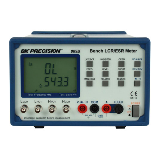
2. Operation 2.1 Physical Description 1. Primary Parameter Display 2. Secondary Parameter Display 3. L/C/Z/DCR Function Key 4. DCA/ACA Function Key 5. Measurement Frequency Key 6. LCUR Terminal 7. Measurement Level Key 8. Range Hold Key 9. Model Number 10. LPOT Terminal 11. -
Page 16: Making Measurement
2.2 Making Measurement 2.2.1 Open and Short Calibration The 889B provides open/short calibration capability so the user can get better accuracy in measuring high and low impedance. We recommend that the user perform open/short calibration if the test level or frequency has been changed. -
Page 17: Dc Resistance Measurement
2.2.4 DC Resistance Measurement The DC resistance measurement measures the resistance of an unknown component by 1VDC. Press the L/C/Z/DCR key to select the DCR measurement. The LCD will display: 2.2.5 AC Impedance Measurement The AC impedance measurement measures the Z of an unknown device. Press the L/C/Z/DCR key to select the Z measurement. -
Page 18: Operation Modes
Operation Modes There are four operation modes in the 889B. They are Normal, Binning, Remote and Remote Binning modes. By pressing the Remote button, users can select one of the 4 operation modes above. Normal Mode: The Normal mode is the default operation mode when power on. It is a local mode that the 889B is controlled by the keypads and the results of the measurement will be sent to both LCD display and a remote USB equipped PC through the build-in USB port. - Page 19 bit position DC/AC V/A Bit 2 – Bit 0 (test freq) Reserved 100 Hz 120 Hz 1K Hz 10K Hz 100K Hz 200K Hz Reserved Reserved Bit 4 – Bit 3 (test level) Reserved 50 mVrms 250 mVrms 1 Vrms Reserved Bit 5 Reserved...
- Page 20 1101 1110 1111 Auto-Ranging Auto-Ranging Bit 17 Short Cal Short Cal Open Cal Reserved Bit 21 – Bit 18 Measurement Modes 0000 Reserved 0001 0010 0011 0100 Diode 0101 Continuity 0110 0111 Others Reserved Bit 23 – Bit 22 Reserved For example: if LCR function, Cp with D measurement mode is selected in Auto-ranging with Relative and Open/Short Calibration are turned off and test signal is 1 Vrms in 1 KHz, then the command is as following: MOD 000001111110001011010010...
-
Page 21: Remote Mode Command Syntax
Data_code : 8 bytes long; two 32-bit floating point format of the secondary reading Checksum : -((02+09+data_code) && 0x00FF) S-B0 S-B1 S-B2 S-B3 S-B0 S-B1 S-B2 S-B3 Remote Mode: When in the Remote mode, the “RMT” on the LCD will be lit and the 889B is capable of communicating to remote USB equipped PC or terminal through the build-in USB port. - Page 22 CsRs(?) Serial capacitance and serial resistance measurement mode setting or querying command. CsQ(?) Serial capacitance and quality factor measurement mode setting or querying command. CsD(?) Serial capacitance and dissipation factor measurement mode setting or querying command. LpRp(?) Parallel inductance and parallel resistance measurement mode setting or querying command.
- Page 23 Example: ASC ON (return) FREQ? 1KHz (return) ASC OFF (return) FREQ? (return) CORR OPEN Perform the open calibration. This command sets the 889B to do the open calibration. After the calibration is done, the 889B will return the “OK” string back. CORR SHORT Perform the short calibration.
- Page 24 Set the measurement level according to the parameter. When setting is done the 889B will return “OK” string. PARAMETER: ASCII string Numerical code 1VDC 1Vrms 250mVrms 50mVrms Example: LEV 1V LEV? Return the current measurement level setting. Example: ASC ON LEV? 1Vrms (return value)
- Page 25 Example: ASC ON MODE? DCV V (return value) RANG mV MODE? DCV mV (return value) RANG(?) PARAMETER Set (query) the measurement unit. RANG PARAMETER Set the measurement unit according to the parameter. “OK” string will be returned when setting is complete. PARAMETER: ASCII string Numerical code...
- Page 26 ASC OFF RANG? (return value) READ? Return the measurement value. This command will perform a measurement according to the current measurement mode and return the measured value. Example: READ? 0.22724 0.12840 (return value) READ? 5.1029 (return value) The “DCR”, “DCV”, and “ACV” measurements will send only one measured value. The other measurement modes will send two measured values separated by space (ASCII 20H).
-
Page 27: Application
4. Application 4.1 Test Leads Connection Auto balancing bridge has four terminals (H and L ) to connect to the device under test (DUT). It is important to understand what connection method will affect the measurement accuracy. • 2-Terminal (2T) 2-Terminal is the easiest way to connect the DUT, but it contents many errors that are the inductance and resistance as well as the parasitic capacitance of the test leads (Figure 4.1). - Page 28 (a) CONNECTION (b) BLOCK DIAGRAM 1m 10m 100m 1 1K 10K 100K 1M (c) Typical Impedance Measurement Range (Ω) Figure 4.3 • 5-Terminal (5T) 5-Terminal connection is the combination of 3T and 4T (Figure 4.4). It has four coaxial cables. Due to the advantage of the 3T and 4T, this connection can widely increase the measurement range for 10mΩ...
- Page 29 Figure 4.4 • 4-Terminal Path (4TP) 4-Terminal Path connection solves the problem that caused by the test lead inductance. 4TP uses four coaxial cables to isolate the current path and the voltage sense cable (Figure 4.5). The return current will flow through the coaxial cable as well as the shield.
-
Page 30: Open/Short Compensation
4.2 Open/Short Compensation For those precision impedance-measuring instruments, the open and short compensation need to be used to reduce the parasitic effect of the test fixture. The parasitic effect of the test fixture can be treated like the simple passive components in figure 4.7(a). When the DUT is open, the instrument gets the conductance Yp = Gp + jωCp (Figure 4.7(b)). - Page 31 • Capacitor The impedance and capacitance in the capacitor are negatively proportional. Therefore, the larger capacitance means the lower impedance, the smaller capacitance means the higher impedance. Figure 4.8 shows the equivalent circuit of capacitor. If the capacitance is small, the Rp is more important than the Rs. If the capacitance is large, the Rs shouldn’t be avoided.
-
Page 32: Limited Three-Year Warranty
5. Limited THREE-Year Warranty B&K Precision Corp. warrants to the original purchaser that its products and the component parts thereof, will be free from defects in workmanship and materials for a period of three years from date of purchase. B&K Precision Corp. will, without charge, repair or replace, at its option, defective product or component parts. Returned product must be accompanied by proof of the purchase date in the form of a sales receipt. - Page 33 Service Information Warranty Service: Please go the service and support section on our website www.bkprecision.com to obtain a RMA #. Return the product in the original packaging with proof of purchase to the address below. Clearly state on the RMA the performance problem and return any leads, probes, connectors and accessories that you are using with the device.
-
Page 34: Safety Precaution
6. Safety Precaution SAFETY CONSIDERATIONS The Models 889B LCR Meter has been designed and tested according to Class 1A 1B or 2 according to IEC479-1 and IEC 721-3-3, Safety requirement for Electronic Measuring Apparatus. SAFETY PRECAUTIONS/SAFETY NOTES The following general safety precautions must be observed during all phases of operation, service, and repair of this instrument. - Page 35 22820 Savi Ranch Parkway Yorba Linda, CA 92887 PN: 481-528-9-001B Printed in Taiwan TEL: 714-921-9095 2009 B&K Precision Corp. FAX: 714-921-6422...
Need help?
Do you have a question about the 889CS and is the answer not in the manual?
Questions and answers