Table of Contents
Advertisement
Quick Links
Advertisement
Table of Contents

Related Manuals for BK Precision 2194


Summary of Contents for BK Precision 2194
- Page 2 Safety Summary The following safety precautions apply to both operating and maintenance personnel and must be followed during all phases of operation, service, and repair of this instrument. Before applying power to this instrument: • Read and understand the safety and operational information in this manual. •...
- Page 3 Electrical Power This instrument is intended to be powered from a CATEGORY II mains power environment. The mains power should be 115 V RMS or 230 V RMS. Use only the power cord supplied with the instrument and ensure it is appropriate for your country of use.
- Page 4 Do not operate instrument if damaged If the instrument is damaged, appears to be damaged, or if any liquid, chemical, or other material gets on or inside the instrument, remove the instrument’s power cord, remove the instrument from service, label it as not to be operated, and return the instrument to B&K Precision for repair.
- Page 5 Servicing Do not substitute parts that are not approved by B&K Precision or modify this instrument. Return the instrument to B&K Precision for service and repair to ensure that safety and performance features are maintained. For continued safe use of the instrument •...
- Page 6 Compliance Statements Disposal of Old Electrical & Electronic Equipment (Applicable in the European Union and other European countries with separate collection systems) This product is subject to Directive 2002/96/EC of the European Parliament and the Council of the European Union on waste electrical and electronic equipment (WEEE), and in jurisdictions adopting that Directive, is marked as being put on the market after August 13, 2005, and should not be disposed of as unsorted municipal waste.
-
Page 7: Table Of Contents
Contents General Information Product Overview Features Contents Dimensions Front Panel Overview Rear Panel Overview Display Overview Getting Started Input Power Requirements Fuse Requirements and Replacement Preliminary Check 2.3.1 Verify AC Input Voltage 2.3.2 Connect Power 2.3.3 Self-Test 2.3.4 Self-Cal 2.3.5 Check Model and Firmware Version 2.3.6 Function Check... - Page 8 Trigger Trigger Source Trigger Mode Trigger Level Trigger Coupling Trigger Holdoff Noise Rejection Trigger Types 6.7.1 Edge Trigger 6.7.2 Slope Trigger 6.7.3 6.7.4 Video Trigger 6.7.5 Window Trigger 6.7.6 Interval Trigger 6.7.7 Dropout Trigger 6.7.8 Runt Trigger 6.7.9 Pattern Trigger Serial Trigger and Decode I2C Trigger and Serial Decode 7.1.1...
- Page 9 10 Cursors 10.1 X Cursors 10.2 Y Cursors 10.3 Make Cursor Measurements 11 Measure 11.1 Type of Measurement 11.1.1 Voltage Measurements 11.1.2 Time Measurements 11.1.3 Delay Measurements 11.2 Automatic Measurement 11.3 All Measurement 11.4 Gate Measurement 11.5 Clear Measurement 12 Display 12.1 Display Type 12.2...
- Page 10 16 Navigate 16.1 Time Navigate 16.2 History Frame Navigate 16.3 Search Event Navigate 17 History 18 Factory Setup 19 Troubleshooting 20 Service Information 21 LIMITED THREE-YEAR WARRANTY...
-
Page 11: General Information
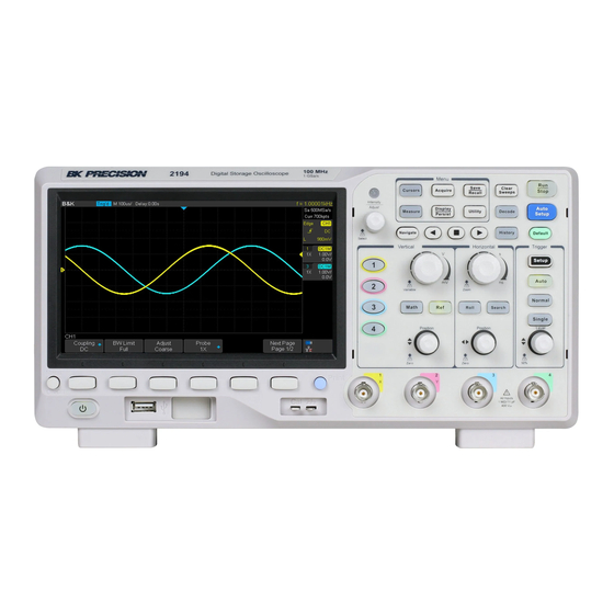
1.1 Product Overview Figure 1.1 2194 Front View The B&K Precision 2194 digital storage oscilloscope (DSO) is a portable benchtop instrument used for making measure- ments of signals and waveforms. This oscilloscope provides 100 MHz of bandwidth in a 4-channel configuration with a maximum sample rate of 1 GSa/s and best-in class memory depth of 14 Mpts. -
Page 12: Dimensions
Ensure the presence of all the items above. Contact the distributor if anything is missing. 1.4 Dimensions The 2194 digital storage oscilloscope’s dimensions are approximately: 312.00 mm (12.28 in) x 151.00 mm (5.94 in) x 132.60 mm (5.22 in) (W x H x D). -
Page 13: Front Panel Overview
General Information 1.5 Front Panel Overview The front panel interface allows for control of the unit. Figure 1.4 Front Panel Item Name Description LCD Display Visual presentation of the device function and measurements. Intensity Adjust Universal knob. Common Used to invoke the functions displayed above them. Function Keys Numeric Keypad Used to enter precise values Rotary Knob... -
Page 14: Rear Panel Overview
General Information 1.6 Rear Panel Overview Figure 1.5 Rear Panel Overview Item Name Description Handle Handle for easy carrying of the instrument. Locks the instrument to a fixed location using the security lock via the lock hole. Safety Lock Hole The lock is not included. -
Page 15: Display Overview
General Information 1.7 Display Overview Figure 1.6 Display Overview Item Name Description Trigger Status Displays the trigger status. USB Host Indicates that a USB is connected to the instrument. Port Indicator LAN Port Indicates the status of the LAN connection. Indicator Menu Bar Displays the available options in the selected menu. -
Page 16: Getting Started
Getting Started Before connecting and powering up the instrument, review the instructions in this chapter. 2.1 Input Power Requirements The oscilloscope has a universal AC input that accepts line voltage and frequency input within: 100 - 240 V (+/- 10%), 50/60 Hz (+/- 5%) 100 - 127 B, 400 Hz 50 W Max Before connecting to an AC outlet or external power source, be sure that the power switch is in the OFF position and... -
Page 17: Preliminary Check
Getting Started Check and/or Change Fuse – Locate the fuse box next to the AC input connector in the rear panel. (See figure 1.5) – Insert a small flathead screwdriver into the fuse box slit to pull and slide out the fuse box as indicated below. –... -
Page 18: Self-Test
Getting Started 2.3.3 Self-Test The instrument has 3 self-test option to test the screen ,keyboard, and the LED back light. To perform the self-test, please refer to the Self Test section for further instructions. 2.3.4 Self-Cal Self option runs an internal self-calibration procedure that will check and adjust the instrument. To perform the self- calibration refer to the Self-Calibration section for further instructions. -
Page 19: Function Check
Getting Started 2.3.6 Function Check Follow the steps below to do a quick check of the oscilloscope’s functionality. 1. Power on the oscilloscope. Press Default Setup to show the result of the self-check. – The probe default attenuation is 1X. 2. -
Page 20: Probe Safety
Getting Started 2.4 Probe Safety A guard around the probe body provides a finger barrier for protection from electric shock. Figure 2.4 Probe Connect the probe to the oscilloscope and connect the ground terminal to the ground before you take any measurements. Shock Hazard: To avoid electric shock when using the probe, keep fingers behind the guard on the probe body. - Page 21 Getting Started Probe Attenuation Probes are available with various attenuation factors which affect the vertical scale of the signal. The Probe Check function verifies that the probe attenuation option matches the attenuation of the probe. Press CH 1 once to open the channel menu. Use the softkeys to navigate to page 1/2 and select the Probe option. Select the probe option that matches the attenuation of the probe.
-
Page 22: Vertical Controls
Vertical Controls 3.1 Enable Channel The 2194 provides 4 analog input channels. To enable a channel press the corresponding channel button located on the vertical controls. The enabled channels can be verified on the right side of the display screen. -
Page 23: Channel Coupling
Vertical Controls 3.2.1 Channel Coupling Coupling mode filters out the undesired signals. Press the corresponding CH button, then use the softkeys to select Coupling. Turn the Universal Knob to select the desired coupling method. Note: The current coupling method is displayed in the channel label at the right side of the screen. Pressing the Coupling softkey continuously switches between the available coupling method. -
Page 24: Probe
Vertical Controls Note: Push the Vertical Variable Knob to quickly switch between Coarse and Fine adjustment. 3.2.4 Probe Sets the probe attenuation factor to match the type of probe being used. 1. Press the CH button of the channel to be configured. 2. -
Page 25: Deskew
Vertical Controls 3.2.6 Deskew Adjust the difference of phase between the channel. The Valid range of each channel is ± 100 ns. 1. Press the CH button of the channel to be configured. 2. Use the softkeys to navigate to page 2/2. 3. -
Page 26: Trace Visible/Hidden
Vertical Controls 3. Use the softkeys to select Offset. 4. Turn the Universal Knob to change deskew. – Pushing the Universal Knob open the keypad. Figure 3.4 Offset Keypad Note: The Vertical Position Knob can be used to offset the waveform’s vertical position without having to enter the chan- nel’s menu. -
Page 27: Horizontal Control
The time base information at the upper left corner of the screen will change accordingly during the adjustment. The 2194 horizontal scale has a range from 2ns/div to 100s/div. The Horizontal Scale Knob works (in the Normal time mode) while acquisitions are running or when they are stopped. -
Page 28: Roll Mode
Horizontal Control To change the time base for the zoom window, turn the Horizontal Scale Knob. The Horizontal Position Knob sets the left- to- right position of the zoom window. The delay value, which is the time displayed relative to the trigger point is momentarily displayed in the upper right corner of the display when the Horizontal Position Knob is turned. -
Page 29: Sample Control
Sample Control 5.1 Run Control Press the Run/Stop or the Single key to stop the sampling system of the scope. • Running: When the Run/Stop key is green, the oscilloscope is continuously acquiring data. – To stop acquiring data, press the Run/Stop key. –... -
Page 30: Bandwidth And Sample Rate
Sample Control The sample rate affect the waveform in the following manner : • Waveform Aliasing: Aliasing occurs when the signal is under-sampled. The signal is distorted by low frequencies falsely being reconstructed from an insufficient number of sample points. Figure 5.2 Low Sample Rate 5.4 Bandwidth and Sample Rate An oscilloscope’s bandwidth is typically described as the lowest frequency at which input signal sine waves are attenuated... -
Page 31: Memory Depth
Sample Control Figure 5.4 Bandwidth Limiting In practice, an oscilloscope’s sample rate should be four or more times its bandwidth: �� . Doing so causes less = 4���� �� ���� aliasing, and aliased frequency components have a great amount of attenuation. 5.5 Memory Depth Memory Depth refers to the number of waveform points that the oscilloscope can store in a single trigger sample. -
Page 32: Sampling Mode
Sample Control 5.6 Sampling Mode The oscilloscope only supports real-time sampling. In this mode, the oscilloscope samples and displays waveform within a trigger event. The maximum real-time sample rate is 1GSa/s. Press the RUN/STOP button to stop the sample, the oscilloscope will hold the last display. When stopped the vertical control and horizontal control are used to pan and zoom the waveform. -
Page 33: Acquisition Mode
Sample Control • Sinx/x Connects the sample points with a curve that has stronger versatility. Sinx interpolation method uses mathe- matical processing to calculation results in the actual sample interval. This method produces a more realistic regular shape than pure square wave and pulse. When the sampling rate is 3 to 5 times the bandwidth of the system, the Sinx/s interpolation method is recommended. - Page 34 Sample Control Normal In Normal mode the oscilloscope samples the signal at equal time interval to rebuild the waveform. For most waveforms, the best display effect can be obtained using this mode. Figure 5.7 Normal Mode Peak Detect In Peak Detect mode, the oscilloscope acquires the maximum and minimum values of the signal within the sample interval to get the envelope of the signal or the narrow pulse of the signal that might be lost.
-
Page 35: Average
Sample Control 5.9 Average In Average mode, the oscilloscope averages the waveforms from multiple samples to reduce the random noise of the input signal and improve the vertical resolution. The greater the number of averages is, the lower the noise will be and the higher the vertical resolution will be. - Page 36 Sample Control Disabled: When XY is disabled, YT mode is set. In YT mode the display is set to a volt versus time graph, and signal events occurring before the trigger are plotted to the left of the trigger point and signal events after the trigger plotted to the right of the trigger point.
-
Page 37: Sequence Mode
400,000 wfs/s. This allows the 2194 to capture small probability event effectively. The 2194 runs and fills a memory segment for each trigger event. The oscilloscope continues to trigger until memory is filled, and then display the waveforms on the screen. -
Page 38: Trigger
6.1 Trigger Source The 2194 trigger source includes four analog channels and AC line. To set the trigger source: 1. Press the Setup key to enter the Trigger menu. -
Page 39: Trigger Mode
Trigger AC Line The trigger signal is obtained from the AC power input of the oscilloscope. This kind of signals can be used to display the relationship between signals (such as illuminating device) and power (power supply device). For example, it is mainly used in related measurement of the power industry to stably trigger the waveform output from the transformer of a transformer substation. -
Page 40: Trigger Level
Trigger Single The oscilloscope waits for a trigger and displays the waveform when the trigger condition is met, the acquisition is stopped when the trigger conditions are met. Single trigger mode is appropriate when: • Capturing a single event or a periodic signal. •... -
Page 41: Trigger Coupling
Trigger 6.4 Trigger Coupling To set the trigger coupling: 1. Press the Setup key to enter the Trigger menu. 2. Press the Coupling softkey to display the available options. 3. Turn the Universal Knob or press the Coupling softkey continually to navigate the available modes. 4. -
Page 42: Trigger Holdoff
Trigger 6.5 Trigger Holdoff Trigger holdoff can be used to add an additional, user-defined delay to the re-arming of the trigger circuit. This provides control over how rapidly, or how often, the oscilloscope can be triggered. The oscilloscope will not trigger until the holdoff time expires. -
Page 43: Noise Rejection
• Remove the noise from the rtigger path setting Trigger coupling to LF Reject, HF Reject, or enabling Noise Reject. • Set the mode to Average to reduce noise. Acquisition 6.7 Trigger Types The 2194 provides the following trigger types : • Edge Trigger • Slope Trigger •... -
Page 44: Edge Trigger
Trigger 6.7.1 Edge Trigger Edge trigger distinguishes the trigger points by seeking the specified edge (rising, falling, alter) and trigger level. Figure 6.8 Edge Trigger Point 1. Press the Setup key to enter the Trigger menu. 2. Press the Type softkey to display the available trigger types. 3. -
Page 45: Slope Trigger
Trigger 6.7.2 Slope Trigger The slope trigger looks for a rising or falling transition from one level to another level in greater than or less than a certain amount of time. In the oscilloscope, positive slope time is defined as the time difference between the two crossing points of trigger level A and B with the positive edge as shown in the figure below. - Page 46 Trigger 6.7.3 The Pulse Trigger type triggers on the positive or negative pulse with a specified width. Figure 6.11 Pulse Trigger 1. Press the Setup key to enter the Trigger Menu. 2. Press the Type softkey to view the available trigger types. 3.
- Page 47 Trigger Figure 6.14 Within a Range of Time Value • - -][- - (outside a range of time value): Trigger when the positive or negative pulse time of the input signal is greater than the specified upper limit of time and lower than the specified lower limit of time value. Figure 6.15 Pulse Trigger Example Coupling and noise reject can be set in pulse trigger, see the sections Trigger Coupling...
-
Page 48: Video Trigger
Trigger 6.7.4 Video Trigger Video triggering can be used to capture the complicated waveforms of most standard analog video signals. The trigger circuitry detects the vertical and horizontal interval of the waveform and produces triggers based on the video trigger settings you have selected. - Page 49 Trigger Table explains the relation between Of Lines, Of Fields, Interlace, Trigger Line and Trigger Field using an Of Lines value of 800. Of Lines Of Fields Interlace Trigger Line Trigger Field 1, 2, 4 or 8 1, 12, 14, 18 1, 2, 4 or 8 1, 12, 14, 18 1, 2, 4 or 8...
- Page 50 Trigger Use a Custom Video Trigger Custom video triggering supports frame rate of 25Hz, 30Hz, 50Hz and 60Hz, and the line range is available from 300 to 2000. The steps below show how to set custom trigger. 1. Press the Setup key to enter the Trigger menu. 2.
-
Page 51: Window Trigger
Trigger 6.7.5 Window Trigger Windows trigger provides a high trigger level and a low trigger level. The instrument triggers when the input signal passes through the high trigger level or the low trigger level. There are two kinds of window types: Absolute and Relative. They have different trigger level adjustment methods. Under Absolute window type, the lower and the upper trigger levels can be adjusted respectively via the Level knob. - Page 52 Trigger Set Window Trigger Via Absolute Window Type 1. Press the Setup key to enter the Trigger menu. 2. Press the Type softkey, then use the Universal Knob to select Window. 3. Press the Source softkey, then use the Universal Knob to select CH1 or CH2 as the trigger source. 4.
- Page 53 Trigger Set Window Trigger Via Relative Window Type 1. Press the Setup key to enter the Trigger menu. 2. Press the Type softkey, then use the Universal Knob to select Window. 3. Press the Source softkey, then use the Universal Knob to select CH1 or CH2 as the trigger source. 4.
-
Page 54: Interval Trigger
Trigger 6.7.6 Interval Trigger Trigger when the times difference between the neighboring rising or falling edges meets the time limit (< =, > =, [ - - . - - ], - - ][ - - ). Figure 6.19 Interval Trigger To set an interval trigger: 1. - Page 55 Trigger Figure 6.20 Interval Trigger Example Note: Coupling and noise reject can be set in interval trigger, see the sections Trigger Coupling and Noise Rejection for details.
-
Page 56: Dropout Trigger
Trigger 6.7.7 Dropout Trigger Dropout trigger includes two types: edge and state. Edge Triggers when an edge followed by a specified time with no edges is detected. This is useful for triggering on the end of a pulse train. Figure 6.21 Dropout Trigger Edge To set an edge dropout trigger: 1. - Page 57 Trigger State Triggers when the signal enters or leaves a voltage level and stays there for a specified time. This is useful for detecting when a signal gets stuck at a particular level. Figure 6.22 Dropout Trigger State To set a state dropout trigger: 1.
-
Page 58: Runt Trigger
Trigger 6.7.8 Runt Trigger The runt trigger detects a pulse that crosses the first threshold but not the second. It can occur when a logic driver has insufficient slew rate to reach a valid logic level in the time available. Figure 6.23 Runt Trigger •... - Page 59 Trigger Figure 6.24 Runt Trigger Example Note: Coupling and noise reject can be set in interval trigger, see the sections Trigger Coupling and Noise Rejection for details.
-
Page 60: Pattern Trigger
Trigger 6.7.9 Pattern Trigger The Pattern trigger identifies a trigger condition by looking for a specified pattern. The pattern trigger can be expanded to incorporate delays. Pattern durations are evaluated using a timer. The timer starts on the last edge that makes the pattern “true”. Potential triggers occur on the first edge that makes the pattern false, provided that the time qualifier criterion has been met. - Page 61 Trigger Note: Adjust the trigger level for the selected analog channel by turning the Trigger Level knob while high or low are selected. Invalid doesn’t need to set trigger level. 5. Press the Next Page softkey to enter the second page of the pattern trigger menu. 6.
-
Page 62: Serial Trigger And Decode
Serial Trigger and Decode The oscilloscope provides I2C, SPI, UART, CAN and LIN serial trigger and decode. This chapter introduces the method of triggering and decoding these serial signals in details. 7.1 I2C Trigger and Serial Decode 7.1.1 Setup for I2C Signals To set the I2C (Inter-IC bus) signal first, connect the serial data signal (SDA) and serial clock signal (SCK) to oscilloscope, then specify the threshold voltage of each input signal. -
Page 63: I2C Trigger
Serial Trigger and Decode 7.1.2 I2C Trigger The I2C trigger has nine trigger conditions: (Start, Stop, Restart, No Ack, EEPROM, 7 Addr&Data, 10 Addr&Data and Data Length) • Start Condition: The oscilloscope will be triggered when the SDA signal transitions from high to low while the SCL clock is high. - Page 64 Serial Trigger and Decode Note: If the data’s value is 0xXX, any data value will be matched. Figure 7.3 7 Address & Data • 10 address & Data: The oscilloscope will be triggered when the following conditions are satisfied: – The address’s length must be 10 bits and the address’s value must be the same as the set value. –...
- Page 65 Serial Trigger and Decode Operation Step 1. Touch Setup key to enter the Trigger menu. 2. Touch Type and select Serial. 3. Touch Protocol and select I2C. 4. Touch Trigger Setting softkey. 5. Touch Condition and turn the Universal Knob to select the trigger condition: Figure 7.5 Condition Options •...
-
Page 66: I2C Serial Decode
Serial Trigger and Decode 7.1.3 I2C Serial Decode Once the setup for I2C signal and trigger has been completed, the decoding operation must be setup. 1. Touch Decode followed by the Decode softkey. – Select one of the options from the Decode1 and Decode2. 2. -
Page 67: Spi Trigger And Serial Decode
Serial Trigger and Decode 7.2 SPI Trigger and Serial Decode 7.2.1 Setup for SPI Signals Setting the SPI (Serial Peripheral Interface) signal includes two steps: Connecting the CLK, MISO, MISO and CS signal to oscilloscope, specifying the parameters of each input signal. 1. - Page 68 Serial Trigger and Decode 7. Set MOSI: • Press the MOSI to enter the MOSI menu. • Touch MOSI to select the channel that is connected to the SPI MOSI signal. • Press the Threshold softkey, then use the Universal Knob to set the SPI MOSI signal’s threshold voltage level. –...
- Page 69 Serial Trigger and Decode Figure 7.12 Example When the CS type is set to Clock Timeout, the clock idle time between frames is T3, the clock period is T1, then set the timeout to a value between T1 and T3 Figure 7.13 Example 2...
- Page 70 Serial Trigger and Decode If the data width is set to be greater than 8 bits (such as 16 bits), the clock idle time between 8-bit data packets T2, and then set the timeout time to a value between T1/2+T2 and T3. Figure 7.14 Example 3...
-
Page 71: Spi Trigger
Serial Trigger and Decode 7.2.2 SPI Trigger This section provides a brief introduction for the operation of the SPI trigger. 1. Touch Setup button to enter the TRIGGER function menu. 2. Touch Type and select Serial. 3. Touch Protocol and select SPI. 4. -
Page 72: Spi Serial Decode
Serial Trigger and Decode 7.2.3 SPI Serial Decode Once the setup of SPI signal and trigger is complete, the SPI signals can be decoded. Operation steps as follows: 1. Touch Decode –>Decode. Select one of the options from the Decode1 and Decode2. 2. -
Page 73: Uart Trigger And Serial Decode
Serial Trigger and Decode 7.3 UART Trigger and Serial Decode 7.3.1 Setup for UART Signals 1. Touch Decode key to enter the DECODE function menu. 2. Touch Decode and select the desired slot (Decode1 or Decode2). 3. Touch Protocol and then select UART by turning Universal Knob. 4. -
Page 74: Uart Trigger
Serial Trigger and Decode 7.3.2 UART Trigger This section includes an introduction and description for the operation of the UART trigger. 1. Touch Setup key to enter the TRIGGER function menu. 2. Touch Type and select Serial. 3. Touch Protocol and select UART. 4. -
Page 75: Uart Serial Decode
Serial Trigger and Decode 7.3.3 UART Serial Decode Upon completing the setup of UART signal and trigger, the UART signals can be decoded. Operation steps as follows: 1. Press Decode –> Decode. Select one of the options from the Decode1 and Decode2. 2. - Page 76 Serial Trigger and Decode Interpreting UART Decode The frames of decoding result: • RX — the decoding result of the data received. • TX — the decoding result of the data transmitted. • Indicates there is not enough space on the display to show the complete content of a frame, and some content is hidden.
-
Page 77: Can Trigger And Serial Decode
Serial Trigger and Decode 7.4 CAN Trigger and Serial Decode Placed in order of to trigger and decode the signals. Setup for CAN Signals, Trigger, CAN Serial Decode 7.4.1 Setup for CAN Signals 1. Touch Decode key to enter the DECODE function menu. 2. - Page 78 Serial Trigger and Decode Operation Steps 1. Touch Setup to enter the TRIGGER function menu. 2. Touch Type and select Serial. 3. Touch Protocol and select CAN. 4. Touch Trigger Setting to enter the CAN TRIG SET menu. 5. Touch Condition and select the trigger condition by turning the Universal Knob: •...
-
Page 79: Can Serial Decode
Serial Trigger and Decode 7.4.1 CAN Serial Decode Upon completing the setup of can signal and trigger, the CAN signals can be decoded. 1. Press Decode –> Decode. Select one of the options from the Decode1 and Decode2. 2. Touch Display and select On to display the result of decoding. 3. -
Page 80: Lin Trigger And Serial Decode
Serial Trigger and Decode 7.5 LIN Trigger and Serial Decode 7.5.1 Setup for LIN Signals There are two steps of setting the LIN signal, connecting the signal to oscilloscope, specifying the parameters of each input signal. 1. Touch Decode button to enter the DECODE function menu. 2. -
Page 81: Lin Trigger
Serial Trigger and Decode 7.5.2 LIN Trigger This section provides a brief introduction and description for the operation of the LIN trigger. Trigger Condition • Break — the oscilloscope will be triggered at the position of break field’s break delimiter. •... - Page 82 Serial Trigger and Decode Figure 7.29 LIN Trigger...
-
Page 83: Interpreting Lin Decode
Serial Trigger and Decode 7.5.1 Interpreting LIN Decode The frame of decoding result: • Protected Identifier Field is displayed in frame • Data Length is displayed in frame • Data Field is displayed in frame. • Checksum Field is displayed in frame. •... -
Page 84: Reference Waveform
Reference Waveform The oscilloscope can save analog channel or math waveforms to the reference waveform locations in the oscilloscope. Then, a reference waveform can be displayed and compared against other waveforms. All reference waveforms can be displayed at a time. 8.1 Save REF Waveform to Internal Memory Do the following steps to save the REF waveform to internal memory: 1. -
Page 85: Adjust Ref Waveform
Reference Waveform 8.3 Adjust REF Waveform 1. Refer to the Display REF Waveform section above to display the desired reference waveform. 2. Press the Scale and Position softkey and turn the Universal Knob to adjust the vertical scale and position of the reference waveform. -
Page 86: Math
Math The oscilloscope supports many math operations between analog channels including addition (+), subtraction (-), multiplication (*), division (/), FFT, differential (d/dt), integral (∫ ����), square root (√). The resulting math waveform is displayed in white and labeled with “M”. You can use cursors to measure it. Note: If the analog channel or the math function is cut off (waveforms do not display on the screen completely), the resulting math will also be cut off. -
Page 87: Math Operators
Math 9.2 Math Operators The oscilloscope supports math count operation (Addition, subtraction, multiplication, division), FFT (Fourier transform) operation, and math function operation (differential, integral, square root). 9.2.1 Addition or Subtraction Math operators perform arithmetic operations add or subtract operation on any two analog input channels. When you select addition or subtraction, the Source A and Source B values are added or subtracted point by point, and the result is displayed. -
Page 88: Multiplication And Division
Math 9.2.2 Multiplication and Division Math operators perform arithmetic operations add or subtract operation on any two analog input channels. When you select multiplication or division, the Source A and Source B values are added or subtracted point by point, and the result is displayed. -
Page 89: Fft Operation
Math 9.2.3 FFT Operation FFT is used to compute the fast Fourier transform using analog input channels. FFT takes the digitized time record of the specified source and transforms it to the frequency domain. When the FFT function is selected, the FFT spectrum is plotted on the oscilloscope display as magnitude in dBV versus frequency. - Page 90 Math Window Applications and Characteristics These are normally used when the signal is transient (completely contained in the time- domain window) or known to have a fundamental frequency component that is an integer Rectangle multiple of the fundamental frequency of the window. Signals other than these types will show varying amounts of spectral leakage and scallop loss, which can be corrected by selecting another type of window.
- Page 91 Math 6. Press the Tools softkey to enter TOOLS menu. Press the Type softkey to select the type of tools. The type of the tools can be Peaks, Markers, or Off. Peaks: Automatically mark the peak of the current FFT waveform according to the search configuration.
- Page 92 Math • Press the Markers on Peaks softkey to set the markers on peaks, and press the Markers on harmonics softkey to set the markers on harmonics. • Press the Show Table softkey to show the amplitude of the markers; press the Show Frequency softkey to show the frequency value of the markers, and press the Show Delta softkey to show the delta amplitude between markers.
-
Page 93: Math Function Operation
Math 9.3 Math Function Operation √ The oscilloscope supports math function operation including differential (d/dt), integral (∫ ����) and square root ( 9.3.1 Differentiate ��(�� + Δ��) − ��(�� − Δ��) ���� = 2Δ�� d/dt (differentiate) calculates the discrete time derivative of the selected source. Where: •... -
Page 94: Integrate
Math 9.3.2 Integrate dt (integrate) calculates the integral of the selected source. You can use integrate to calculate the energy of a pulse in volt-seconds or measure the area under a waveform. dt plots the integral of the source using the "Trapezoidal Rule". The equation is: ��... - Page 95 Math Figure 9.14 Square Root...
-
Page 96: Cursors
Cursors Cursors are horizontal and vertical markers that indicate X-axis values and Y-axis values on a selected waveform source. Cursors can be used to make custom voltage and time measurements on the oscilloscope signals. 10.1 X Cursors X cursors are vertical dashed lines that adjust horizontally and can be used to measure time (when the source is FFT waveform, X cursors measure frequency). -
Page 97: Y Cursors
Cursors 10.2 Y Cursors Y cursors are horizontal dotted lines that adjust vertically and can be used to measure voltage (V) or current (A). When the cursors source is the math function, the unit will match the math function. Y1 cursor is the top (default position) horizontal dotted line; it can be moved to any vertical place of the screen. Y2 cursor is the down (default position) horizontal dotted line;... -
Page 98: Make Cursor Measurements
Cursors 10.3 Make Cursor Measurements 1. Press the Cursors key on the front panel to enter the CURSOR function menu. 2. Press the Mode softkey and set the cursors mode to Manual or Track. 3. Press the Source softkey, and then use the Universal Knob to select the desired source. Only analog channels, math waveforms and reference waveforms that are displayed are available for cursors. -
Page 99: Measure
Measure The oscilloscope provides measurements of 36 waveform parameters and the statistics. It contains voltage, time, and delay parameters. Voltage and time parameters are under Type option. The results of the last four selected measurements are displayed at the bottom of the screen and above the menu. Delay parameters are under All Measure submenu. Set the Delay option to On to display all the delay parameters. - Page 100 Measure 13. Overshoot: Overshoot is distortion that follows a major edge transition expressed as a percentage of Amplitude. ROV means rising edge overshoot and FOV means falling edge overshoot. Figure 11.2 Overshoot ���������� �� ������������ − �� �� ���� ������������ �������� ����������ℎ������ = ��...
-
Page 101: Time Measurements
Measure 11.1.2 Time Measurements Time measurements includes 11 types of time parameter measurements. Figure 11.4 Time Measurements 1. Period: Period for every cycle in waveform at the 50% level, and positive slope. 2. Frequency: Frequency for every cycle in waveform at the 50% level ,and positive slope 3. -
Page 102: Automatic Measurement
Measure 9. FFLF: Time from the first falling edge of channel A to the last falling edge of channel B. 10. SkewTime of source A edge minus time of nearest source B edge. 11.2 Automatic Measurement Perform the steps below and select voltage or time parameters to make automatic measurement. 1. - Page 103 Measure Figure 11.6 New Measurement Note: If the parameter does not match the measure condition, it will display as “****”...
-
Page 104: All Measurement
Measure 11.3 All Measurement All measurement could measure all the voltage, time and delay parameters of the current measurement source and display the results on the screen. Figure 11.7 All Parameters To display all parameters: 1. Press the Measure key on the front panel to enter the MEASURE function menu. 2. -
Page 105: Gate Measurement
Measure 11.4 Gate Measurement The 2194 supports gate measurements and performs the selected measurement within the upper and lower limits of the gate. Setting the gate will affect the measurement of all voltage, time, and delay parameters. 1. Press Measure –> Gate –> On to open the gate measurement. -
Page 106: Display
Display The display type, color, persistence, grid type, waveform intensity, grid brightness and transparence can be configured. 12.1 Display Type Press the Display key on the front panel, then press the Type softkey to select Vectors or Dots display type. •... -
Page 107: Color Display
Display Figure 12.2 Dots Display 12.2 Color Display Color temperature adopts the change of waveforms’ color to reflect the change of the waveforms’ appearing probability. The greater the probability that the waveform appears, the warmer the color is; the smaller the waveform appears, the colder the color is. -
Page 108: Persistence
Display 12.3 Persistence With persistence, the oscilloscope updates the display with new acquisitions, but does not immediately erase the results of previous acquisitions. All previous acquisitions are displayed with reduced intensity. New acquisitions are shown in their normal color with normal intensity. To set and clear persistence: 1. -
Page 109: Clear Display
Display 12.4 Clear Display Press the Display key on the front panel to enter the DISPLAY function menu; press the Clear Display softkey to clear all the waveforms displaying on the screen and acquire and display new waveforms. 12.5 Grid Type To select a grid type: 1. -
Page 110: Transparence
Display 12.8 Transparence Transparence can be used to adjust the transparence of the message box of cursor, measure, Pass/Fail and all pop-up menus to an appropriate value to observe the date more conveniently. Under Cursor or Measure or any other menu operation, if want to change the transparence of the message box, do the following steps: 1. -
Page 111: Save And Recall
Save and Recall Oscilloscope setups, waveforms, pictures, and CSV files can be saved to internal oscilloscope memory or to a USB storage device. The saved setups, waveforms can be recalled later. The oscilloscope provides a USB Host interface on the front panel to connect an USB device for external storage. -
Page 112: Internal Save And Recall
Save and Recall 13.2 Internal Save and Recall Internal save and recall support Setups in Save/Recall. In the following part, the save and recall method and procedures are introduced. Save the specified oscilloscope setting in internal memory. 1. Connect the signal to the oscilloscope and obtain stable display. 2. -
Page 113: External Save And Recall
Save and Recall 13.3 External Save and Recall Before using external storage and recall, a USB flash device must be connected correctly. External storage supports all the types of files in save, but picture and CSV are not supported when recalling. Save the specified type of file in the external USB flash device. - Page 114 Save and Recall Figure 13.2 Select Save Location 6. After the save position is selected, press the New softkey to turn on the interface as shown in the figure below. Refer to the descriptions in “To Create a new file or fold” to create a new file name. Figure 13.3 File Name 7.
-
Page 115: Disk Management
Save and Recall Load the specified type of file in the external USB storage device. 1. Press the Save/Recall key on the front panel to enter the SAVE/RECALL function menu. 2. Press the Recall softkey to enter the RECALL menu. 3. -
Page 116: Delete A File Or Folder
Save and Recall 13.4.2 Delete a File or Folder This operation is only valid in external storage. 1. Press the Save/Recall key on the front to enter the SAVE/RECALL function menu. 2. Press the Save softkey, and then turn the Universal Knob to select one of the type (if select Setups, please set the Save To option to External). -
Page 117: System Settings
System Settings This function module supports the oscilloscopes’s system-related function, such as system status, language, sound and some other advanced setting, such as do self-cal, update and remote interface configure. 14.1 View System Status To view the system status: 1. Press the Utility key on the front to enter the UTILITY function menu. 2. -
Page 118: Self Cal
System Settings 14.2 Self Cal The self-calibration program can quickly make the oscilloscope reach the best working state to get the most precise measurement values. You can perform self-calibration at any time especially when the change of the environment temperature is up to more than 5 ℃. make sure that the oscilloscope has been warmed up or operated for more than 30 minutes before the self-calibration. -
Page 119: Sound
System Settings 14.4 Sound When the sound is enabled, you can hear the sound of the beeper when you press a function key or a menu softkey or when the prompt message pops up. Press the Utility key on the front panel to enter the UTILITY function menu; then press Sound softkey to select to turn on or off the sound. -
Page 120: Set And Perform A Pass/Fail Test
System Settings 14.6.1 Set and Perform a Pass/Fail Test To set and perform pass/fail test: 1. Press the Utility key on the front panel to enter the UTILITY function menu. 2. Press the Next Page softkey to go to the second page of the UTILITY function menu. 3. -
Page 121: Save And Recall Test Mask
System Settings 14.6.2 Save and Recall Test Mask The current test mask can be saved to the internal Flash memory or external USB flash device. the file format of the test mask file is "*.msk". Save Test Mask to Internal Memory 1. - Page 122 System Settings Save Test Mask to External Memory To save the test mask to external memory: 1. Press the Utility key on the front panel to enter the UTILITY function menu. 2. Press the Next Page softkey to go to the second page of the UTILITY function menu. 3.
-
Page 123: Io Set
System Settings 14.7 IO Set The oscilloscope provides the following input output interfaces: USB, LAN, and Auc Output. 14.7.1 LAN To set the oscilloscope to communicate with PC via LAN: 1. Connect the oscilloscope to your local area network using the network cable. 2. -
Page 124: Usb Device
System Settings 14.7.2 USB Device To set the oscilloscope to communicate with a PC via USB: 1. Install the USBTMC device driver on PC. Suggest you install NI Vista. 2. Connect the oscilloscope with PC using a standard USB cable 3. -
Page 125: Do Self-Test
System Settings 8. After finish the update, the screen will pop-out the message “Firmware decompressed. Please restart and wait…” 9. Restart the oscilloscope to finish the configuration update. 14.9 Do Self-Test Self-test includes a screen test, keyboard test, and LED test. 14.9.1 Screen Test 1. -
Page 126: Keyboard Test
System Settings 14.9.2 Keyboard Test Keyboard test is used to test the keys and knobs. To perform a keyboard test: 1. Press the Utility key on the front panel to enter the UTILITY function menu. 2. Press the Next Page softkey to go to the second page of the UTILITY function menu. 3. -
Page 127: Led Test
System Settings 14.9.3 LED Test LED test is used to test the LEDs. 1. Press the Utility key on the front panel to enter the UTILITY function menu. 2. Press the Next Page softkey to go to the second page of the UTILITY function menu. 3. -
Page 128: Screen Saver
System Settings 14.10 Screen Saver When the oscilloscope enters the idle state and holds for a certain period of time, the screen saver program will be enabled. To set the screen saver time: 1. Press the Utility key on the front panel to enter the UTILITY function menu. 2. -
Page 129: Reference Position
System Settings 14.11 Reference Position The reference position setting determines the physical point that the oscilloscope uses during vertical and horizontal scale changes. In some situations, it is more convenient to use a fixed position on the display. 1. Press the Utility key on the front panel and then press the Reference Pos. softkey to enter the Reference POS menu. -
Page 130: Search
1. Press the Search key on the front panel to enter the SEARCH function menu. 2. Press the Mode softkey and then use the Universal Knob to select the desired search type. the 2194 provides five search types: Edge, Slope, Pulse, Interval, Runt. -
Page 131: Results
Search 4. Press Copy softkey to enter COPY function menu. • Copy from Trig: copy the trigger setup for the selected search type to the search setup. • Copy to Trig: copy the setup for the selected search type to the same trigger type •... - Page 132 Search When the acquisition is stop, “EVENT NUM: 4/7” means current event number/total events number, the current event is the closest event to the middle of the screen. Figure 15.3 Search in Run...
-
Page 133: Navigate
Navigate The 2194 provides three navigate types: Search Event, Time , History Frame. 16.1 Time Navigate 1. Press the Navigate key on the front panel to enter the NAVIGATE function menu. 2. Press the Type softkey In the NAVIGATE function menu, then select Time. -
Page 134: History
History The history function can record the waveforms of the input channels before press the Run/Stop button. In run state, the oscilloscope records input waveform continually; when the memory is full (reach the maximal frame), the new frames will cover the old frames and keep the latest frames. To use the History function, the HORIZONTAL Format must be set to YT. -
Page 135: Factory Setup
Factory Setup Press Save/Recall function key, then press Save menu select To Default Key set the type to Factory Setup. Then press the Default button on the front to set the oscilloscope to the leave factory setup. Another way is press Save/Recall function key, then press Recall menu select Factory Default to recall. -
Page 136: Troubleshooting
The commonly encountered failures and their solutions are listed below. When you encounter those problems, please solve them following the corresponding steps. If the problem remains still, please contact BK Precision. The screen is still dark (no display) after power on 1. - Page 137 3. Make sure that the USB storage device being used is flash storage type. This oscilloscope does not support hardware storage type. 4. Restart the instrument and then insert the USB storage device to check it. 5. If the USB storage device still cannot be used normally, please contact BK Precision.
-
Page 138: Service Information
Service Information Warranty Service: Please go to the support and service section on our website at bkprecision.com to obtain an RMA #. Return the product in the original packaging with proof of purchase to the address below. Clearly state on the RMA the performance problem and return any leads, probes, connectors and accessories that you are using with the device. -
Page 139: Limited Three-Year Warranty
LIMITED THREE-YEAR WARRANTY B&K Precision Corp. warrants to the original purchaser that its products and the component parts thereof, will be free from defects in workmanship and materials for a period of three years from date of purchase. B&K Precision Corp. will, without charge, repair or replace, at its option, defective product or component parts. Returned product must be accompanied by proof of the purchase date in the form of a sales receipt.
Need help?
Do you have a question about the 2194 and is the answer not in the manual?
Questions and answers