
Subscribe to Our Youtube Channel
Related Manuals for BK Precision 8500 Series


Summary of Contents for BK Precision 8500 Series
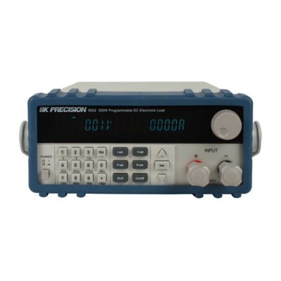
- Page 1 99 Washington Street Melrose, MA 02176 Fax 781-665-0780 TestEquipmentDepot.com Instruction Manual Model 8500 300W DC Electronic Load...
-
Page 2: Environmental Conditions
Warranty Information Certification We certify that this product met its published specifications at time of shipment from the factory. Safety Summary The following general safety precautions must be observed during all phases of operation of this instrument. Failure to comply with these precautions or with specific warnings elsewhere in this manual violates safety standards of design, manufacture, and intended use of the instrument .We assumes no liability for the customer’s failure to comply with these requirements. -
Page 3: Ground The Instrument
Ground The Instrument This product is a Safety Class 1 instrument (provided with a protective earth terminal). To minimize shock hazard, the instrument chassis and cover must be connected to an electrical ground. The instrument must be connected to the ac power mains through a grounded power cable, with the ground wire firmly connected to an electrical ground (safety ground) at the power outlet. - Page 4 ___________________________________________________________________ WARNING The WARNING sign denotes a hazard. It calls attention to a procedure, practice, or the like, which, if not correctly performed or adhered to, could result in personal injury. Do not proceed beyond a WARNING sign until the indicated conditions are fully understood and met.
-
Page 5: The Rear Panel
Scroll through front panel. Entry keys:( numeric keys) Enter values. Increasing or decreasing the setup values. Menu commands. Power switch ON/OFF Input terminals. The Rear Panel 4 Pin Trigger and Remote sensing connectors. 9-Pin COM port interface connector. Power switch (110V / 220V) 3 Pin IEC320 ac input connector. -
Page 6: Front Panel Annunciators
Front Panel Annunciators power off Indicates that the electronic load is Trigger waiting an initiate and trigger to occur. Constant current (CC) mode. Indicates that the electronic load is Sense in Remote sensing state Constant voltage (CV) mode. A errors have occurred Error Constant power (CW) mode. - Page 7 Switch to B setting value Shift Press to store an existing electronic load state in non-volatile Memory. Shift store Press to recall an existing electronic load state in non-volatile Memory. Shift Recall Enter operation Menu. Shift Menu Turn on or turn off short circuit Test. Shift Short Start /Stop transition operation...
-
Page 8: Front Panel Menus
Front Panel Menus I-set V-set POWER Tran P-set R-set ENTER Store Recall S-Tran Menu Shift Input on/off Local Battery Short Trigger Key Pad 0 through 9 are used for entering numeric values. Decimal point. The escape key. It may used to exit any working state. I-set Choosing CC mode and setup the input current of regulation current mode. -
Page 9: Menu Operation
Menu Operation Press Menu to indicate operation mode .View the menu in VFD and using ? ENTER to scroll through the completely menu list as following .IF press key, you could get the selected menu function. Press back to the previous menu selection page. - Page 10 9600 19200 38400 COMM. PARITY SET Command parity setting. NONE<DEFAULT> EVEN ADDRESS SET Setting communication Flow mode KEY LOCK SET Setting keypad password. ENTER Press directly to disable the key lock function. EXIT SYSTTEM SET MAX CURRENT SET Setup the Maximum current. MAX POWER SET Setup the Maximum Power.
-
Page 11: Options And Accessories
Options and Accessories Options IT-E151 Rack mounts kit: for install one or two 8500 series load on the 19 inch rack. ITE-131 isolated communication cable: This cable converts the Electronic Load’s serial port (TTL 5V level) to PC RS232 interface... -
Page 12: Features And Capabilities
Accessories Power cord User’s manual Software CD-Rom Description The 8500 serial Electronic Load is used for design, manufacturing, and evaluation of DC power supplies, batteries, and power components and so on. The Electronic load contains a processor, serial port connector, front-panel keypad and VFD, and other circuits common to the other entire load module. -
Page 13: Remote Programming
Remote Programming The electronic load may be remotely programmed from the computer via the IT-E131 isolated communication cable. Operating Modes The four modes of operation are: 1: Constant current (CC). 2: Constant voltage (CV). 3: Constant resistance (CR). 4: Constant power (CW) Constant Current( CC) Mode In this mode, the electronic load will sink a current in accordance with the programmed value regardless of the input voltage. - Page 14 SLOPE LOAD RESISTANCE CURRENT SETTING LOAD INPUT VOLTAGE CONSTANT RESISTANCE MODE Constant Voltage (CV) Mode In this mode, the electronic load will attempt to sink enough current to control the source voltage to the programmed value. The module acts as a shunt voltage regulator when operating in the CV mode.
-
Page 15: Transient Operation
POWER SETTING LOAD INPUT VOLTAGE LOAD CURRENT CONSTANT POWER MODE Transient Operation Transient operation enables the electronic load to periodically switch between two load levels, as might be required for testing power supplies. A power supply's regulation and transient characteristics can be evaluated by monitoring the supply's output voltage under varying combinations of load levels, frequency, and duty cycle. -
Page 16: Trigger Mode
Pulse Switch to value B as receiving one trigger signal , taking the pulse time(TWD) of value B , Load will return to Value A . 10ms 10ms TRIG TRIG Pulsed Transient Operation Trigger Mode Switching the state between value A and value B once receiving a triggering signal Toggled Transient Operation List Operation List mode lets you generate complex sequences of input changes with rapid, precise... -
Page 17: Triggered Operation
1000 steps 500 steps 500 steps 250 steps 250 steps 250 steps 250 steps steps steps steps steps steps steps steps steps When receiving one trigger signal, it will start the list operation until receiving another trigger signal or finish the List operation. Trigger List count=1 List count=2... -
Page 18: Input Control
Input Control Short On/Off Load can simulate a short circuit at its input by turning the load on with full-scale current. The short circuit can be toggled on/off at the front panel using the Short Shift .Short operation is not influence the operation setting current value , When short operation is on OFF state , Load back to the original setting state. -
Page 19: Protection Features
Rated voltage Rated power Input current I Rated current Operation mode change state Rated voltage Software Power Limit Software Current Limit Input current I Rated current Protection Features Electronic load includes the following protection features: Over Voltage If input voltage exceeds the voltage limit, Load will turn OFF the input, Buzzer is mooing. -
Page 20: Remote Sense Function
Over Current When work in the CR or CC and CP mode, input current is ascending continuously, the load current will be limited by a current limit circuit, Load will work in the over current protection state , VFD display the information as CC. When work in CV mode and transition mode and List mode, Input current exceeds the current limit, Buzzer is mooing, VFD display the flashing current value. -
Page 21: Saving And Recalling Settings
Saving And Recalling Settings The electronic load has internal registers in which settings (mode, current, voltage, Store Shift resistance, transient level, etc.).Users could use Shift Recall to save and recall the relative data as following: CC value /CW value /CR value /CV value Transition current A value /Transition current B value /Transition voltage A value /Transition voltage B value / Transition power A value /Transition power B value /Transition Resistance A value /Transition Resistance B value... -
Page 22: External Control Signals
Battery Voltage Min voltage Load Sink Current External Control Signals Electronic Load has a 4-pin connector mounted on its rear panel. These signals are described in the following paragraphs. Remote Sensing: SENSE (+) and SENSE (–) are the remote sensing inputs. By eliminating the effect of the inevitable voltage drop in the load leads, remote sensing provides greater accuracy by allowing the load to regulate directly at the source's output terminals. - Page 23 Installation Inspection Damage When you receive your electronic load, inspect it for any obvious damage that may have occurred during shipment. If there is damage, notify the shipping carrier and nearest Agent office and Support Office immediately. Items Supplied The following user replaceable items are included with your electronic load. Item Description Power Cord...
-
Page 24: Installation
Installation :101mmW x 215mm H x 366mm D Dimension Terminal length: 29.4mm Feet height:17.5mm Outline Diagram Unit (mm) -
Page 25: Carrying Handle
Carrying Handle Bench Operation A fan cools the electronic load by drawing air through the button and sides and exhausting it out the back. Minimum clearances for bench operation are 25 mm along the sides. ___________________________________________________________________ CAUTION Do not block the fan exhaust at the rear of the Load. ___________________________________________________________________ Rack Mounting The 8500 serial electronic load can be mounted in a standard 19-inch rack. - Page 26 Rack Installation Elevation for Installation one electronic load in a standard 19-inch rack Side elevation for Installation one electronic load in a standard 19-inch rack Elevation for Installation two electronic loads in a standard 19-inch rack...
- Page 27 NOTE Remove the carrying handle and the two plastic ears before rack-mounting the instrument. To remove the handle, grasp the handle by sides and pull outwards and rotate it to a special position to let the arrow on the handle oppose the another arrow on the plastic ears, then pull the handle outward.
-
Page 28: Computer Connections
Trigger And Remote Sensing Connections A 4-pin connector and a quick-disconnect mating plug are provided on rear panel for accessing input signals and remote sensing, all leads connected to the connector should be twisted and shielded to maintain the instrument's specified performance. Remote Sensing: sense ( + ) and sense ( - ) Used to connect the remote sensing leads to the power source. -
Page 29: Turn-On Checkout
CAUTION Users must use IT-E131 to realize the remote operation between PC and 8500 series electronic load. Turn-On Checkout Introduction Successful tests in this chapter provide a high degree of confidence that the electronic load is operating properly. Checkout Procedure The test in this section checks for proper operation of the electronic load. - Page 30 Display the 4. Press Shift button and LOAD MODEL:IT85XX keys . information of the product Type, series SN: XXX-XXX-XXX number version of software. VER x.xx Display the actual 0.000V 0.000A 5. Press button input voltage and current value. 6.Press ? ? Display the actual 0.000W I: 0.000A...
-
Page 31: Front Panel Operation
4) Location of Fuse FUSE Front Panel Operation Introduction: Here is what you will find in this chapter: A complete description of the front panel controls Front panel programming examples. -
Page 32: Function Keys
Display 16-character fluorescent display for showing measurements and programmed values. Annunciators Annunciators light to indicate operating modes and status conditions: Trigger power off Indicates that the electronic load is waiting an initiate and trigger to occur. The selected input channel is in Sense Indicates that the electronic load is the constant current (CC) mode. -
Page 33: Entry Keys
Entry Keys Entry keys let you: Enter programming values. Increasing or decreasing setup values. Press ? or ? select the front panel menu parameters. Power The Power switch turns the electronic load power on or off. Example I-set (set up a constant current from 0 to Max current ) Set up a constant DC current input is the first main function of programmable DC electronic load,... - Page 34 Step5. Press button to confirm the current value. P-set (set up a constant power from 0 to Max power) 8500 series electronic load can be set up for a constant power. Constant power setup procedure is as following: Procedure Operation details...
- Page 35 0.000W P:*.000W ENTER Press to confirm. R-set (set up a constant resistance from 0.1 4000 8500 series electronic load can be setup for a constant resistance. Constant resistance setup procedure is as following: Procedure Operation details VFD display Step 1...
-
Page 36: Menu Description
Shift + Store Procedure Operation details VFD display Step 1 STORE 1 Shift Store Press Step 2 Store the relative data ENTER Press to confirm. Shift + Recall Procedure Operation details VFD display Step 1 RECALL 1 Shift Recall Press Step 2 Recall the saving data ENTER... - Page 37 the ? TRIGGER SOURUSE button to BAUDRATE SET change the COMM.PARITY SET selecting ADDRESS SET function, KEY LOCK SET press EXIT ENTER button SYSTEM SET to execute MAX CURRENT SET ENTER the selection MAX POWER SET function or MAX VOLTAGE SET step into the EXIT next...
-
Page 38: Continuous Transient Operation
WIDTH A = ****** Setup time width of value A ENTER LEVEL B=***** Setup value B ENTER Setup time width of value B WIDTH B= ***** ENTER Choose one of the three CONTINUOUS ENTER PULSE transition modes TOGGLED Finish transition setting ENTER Continuous Transient Operation In this mode, electronic load will generates a repetitive pulse stream that... -
Page 39: Pulse Transient Operation
Pulse Transient Operation In this mode, generates a transient pulse of programmable width when pulsed transient operation is in effect. For example: When load receiving one trigger signal, it will switch to 10A current value, and taking 10mS to return the current value of 5A. 10ms 10ms TRIG... - Page 40 Toggled Transient Operation Action Shift S-Tran 1. Press , Setting LEVER A=5A, LEVER B=10A, Transition mode is PULSE . Shift Tran 2. Press to activate the transient mode. Shift Trigger 3. Press switch to the current value of 10A. Shift Trigger 4.
- Page 41 Shift Menu , move cursor to the option of menu of CONFIG , 2) Press ENTER Press into the next step menu ,move cursor to TRIGGER ENTER SOURCE . Press and move cursor to IMMEDIATE <DEF>, setting trigger source mode is panel IMMEDIATE mode. ENTER 3) Press to confirm.
-
Page 42: Specifications
Specifications 8500 Parameter Input rating Voltage 0 to 120V ( 0 ~ 40 ? ) Current 1mA to 30A Power 300 W Load Range Accuracy Resolution Regulation ±(0.05%+0.02%FS) 0-18V ±(0.05%+0.025%FS) 0-120V / 500V 10mV ±(0.1%+0.1%FS) 0-3A 0.1mA ±(0.2%+0.15%FS) 0-30A / 15A ±(0.05%+0.02%FS) CV Mode 1.5-18V... -
Page 43: Remote Operation Mode
Remote Operation Mode DB9 in the rear panel of electronic load could connect with RS-232 through on TTL connector. The following information may help you to know how to control the output of Electronic load through PC. 1. Communication Setting Ensure setting the same baud rate in the communication address of Electronic load and computer software .otherwise, the communication will fail. -
Page 44: Frame Format
IT-E131 communication cable Load IT-E131 ISOLATED COMMUNICATION CABLE RS232 ISOLATION TTL(5V) 859666668889942311 CAUTION Forbidden to connect DB9 connector in Electronic load directly with PC or other RS232 port. 3. Frame Format Frame length is 26 bytes. Details as following: Addres Comman 4—25bytes are information Parity code... - Page 45 Reading the operation mode. 2AH Setting CC mode current value 2BH Reading CC mode current value 2CH Setting CV mode voltage value 2DH Reading CV mode voltage value 2EH Setting CW mode watt value Reading CW mode watt value Setting CR mode resistance value Reading CR mode resistance value Setting CC mode transient current and timer parameter.
- Page 46 Reading timer state of FOR LOAD ON Setting communication address Enable/Disable LOCAL control mode. Enable/Disable remote sense mode. Reading the state of remote sense mode. Selecting trigger source. Reading trigger source. 5AH Sending a trigger signal to trigging the electronic load. 5BH Saving user’s setting value in appointed memory area for recall.
-
Page 47: Communication Protocol
4. Communication Protocol 1. Selecting the Remote control mode( 20H) byte Start bit ( AAH ) byte Address (0—0XFE) Command( 20H) byte Operation mode( 0 is front panel operation mode , 1 is remote .byte operation mode ) From 5 to 25 byte System reserve... - Page 48 NOTE Represent a voltage upper limit value by 4 bytes of Hex. Lower bytes are in the front location, higher bytes are in the later location. 1 represent 1mV.For Example : The voltage upper limit is 16.000V, the hex code is 0X00003EB0, then the 4th byte is 0XB0, 5th byte is 0X3E, 6th byte is 0X00, 7TH byte is 0X00? 4.
- Page 49 From 8 to 25 byte System reserve byte Sum code NOTE Represent power value by 4 bytes of Hex. Lower bytes are in the Front location, higher bytes are in the later location. 1 represents 1mW. If setting upper value is 200.000W, the hex code is 0X00030d40, then the 4th byte is 0X40, 5th is 0X0d, 6th is 0X03, 7th is 0X00? 6.
- Page 50 byte Sum code NOTE Represent current by 4 bytes of Hex. Lower bytes are in the front location, higher bytes are in the later location. For example: current is 3.0000A, Hex code is 0X00007530, NO. 4 bye is 0X30, NO. 5 bye is 0X75, NO. 6 bye is 0X00, NO.
- Page 51 Command( 2EH/2FH) byte byte The lowest byte of max power value byte The lower byte of max power value byte The higher byte of max power value byte The highest byte of max power value to 25 byte System reserve byte Sum code NOTE...
- Page 52 11. Setting /Reading CC mode transient current and timer parameter. ( 32H/33H) byte Start bit ( AAH ) byte Address (0—0XFE) Command( 32H/33H) byte From 4 byte to 7 Setting value of current A (Lower bytes are in the front location, byte higher bytes are in the later location.) From 8...
- Page 53 byte Transient operation mode (0 is CONTINUES,1 is PULSE,2 is TOGGLED) From 17 to 25 System reserve byte byte Sum code 13. Setting /Reading CW mode transient watt and timer parameter( 36H/37H) byte Start bit ( AAH ) byte Address (0—0XFE) Command( 36H/37H) byte From 4...
- Page 54 From 8 byte to 9 Time value of timer A (Lower bytes are in the front location, higher byte. bytes are in the later location) (1 represent 0.1mS) From 10 byte to Setting value of resistance B (Lower bytes are in the front location, byte higher bytes are in the later location) From 14...
- Page 55 17. Setting / Reading the number of list steps. (3EH/3FH) byte Start bit ( AAH ) byte Address (0—0XFE) Command( 3EH/3FH) byte From 4 to 5 byte LIST steps From 6 to 25 byte System reserve byte Sum code 18. Setting / Reading one of the step’s current and time values.
- Page 56 From 6 byte to 9 Voltage value of current step (Lower bytes are in the front location, byte higher bytes are in the later location) From 10 to 11 Time value of current step (Lower bytes are in the front location, byte higher bytes are in the later location) (1 represent 0.1MS)
- Page 57 byte Sum code 22. Setting / Reading List file name (48H/49H) byte Start bit ( AAH ) byte Address (0—0XFE) Command ( 48H/49H) byte From 4 to 13 byte LIST file name (ASSIC code ) From 14 to 25 System reserve byte byte Sum code...
- Page 58 25. Setting / Reading min voltage value in battery testing mode.( 4EH/4FH) byte Start bit ( AAH ) byte Address (0—0XFE) Command( 4EH/4FH) byte byte The lowest byte of voltage value. byte The lower byte of voltage value. byte The higher byte of voltage value. byte The highest byte of voltage value.
- Page 59 byte Timer state (0 is disable ,1 is enable ) From 5 to 25 byte System reserve byte Sum code 28. Setting communication address (54H) byte Start bit ( AAH ) byte Address (0—0XFE) Command ( 54H) byte byte New communication address (0~0XFE) From 5 to 25 byte...
- Page 60 byte Trigger mode (0:Keypad,1 External,2.command) From 5 to 25 byte System reserve byte Sum code 32. Sending a trigger signal to trigging the electronic load. (5AH) byte Start bit ( AAH ) byte Address (0—0XFE) Command( 5AH) byte From 4 to 25 byte System reserve...
- Page 61 35.Reading input voltage, current, power and relative state. (5FH) byte Start bit ( AAH ) byte Address (0—0XFE) Command ( 5FH) byte From 4 to 7 byte Actual input voltage value (Lower bytes are in the front location, higher bytes are in the later location) From 8 to 11 byte...
- Page 62 36. Enter the calibration mode( 60H) byte Start bit ( AAH ) byte Address (0—0XFE) Command( 60H) byte byte Calibration mode select(0:disable;1:enable) Calibration password( 0X85H) byte Calibration password( 0X11H or 0X12H) byte From 7 to 25 byte System reserve byte Sum code NOTE If Load is not in protection state, users could do the calibration operation.
- Page 63 38. Calibrate voltage value( 62H) byte Start bit ( AAH ) byte Address (0—0XFE) Command( 62H) byte Voltage calibration point( 1~4) byte From 5 to 25 byte System reserve byte Sum code NOTE Current calibration standard points have four: 1, 2, 3, 4. 39.
- Page 64 NOTE Current calibration standard points have four: 1,2,3,4 41. Sending the actual input current to calibration program (65H) byte Start bit ( AAH ) byte Address (0—0XFE) Command( 65H) byte byte The lowest byte of actual current byte The lower byte of actual current byte The higher byte of actual current byte...
- Page 65 Command( 67H/68H) byte Demarcate information( ASIC code) From 4 to 23 byte byte System reserve byte System reserve byte Sum code 44. Restore the factory default calibration data ( 69H) byte Start bit ( AAH ) byte Address (0—0XFE) Command( 69H) byte From 4 to 25...
- Page 66 Product’s series number is 000045, product mode is 8511,software version number is V2.03, data as following 46. Reading information in bar code (6BH) byte Start bit ( AAH ) byte Address (0—0XFE) Command ( 6BH) byte Information in bar code( ASIC ? ) From 4 to 22 byte...
- Page 67 byte Address (0—0XFE) Command( 12H) byte byte Command calibration result From 5 to 25 byte System reserve byte Sum code NOTE Receiving one frame command and verify them If verify sum is wrong, return the parameter 90H If setting parameter is wrong or over brim, return parameter A0H. If command is not enforce, return to parameter B0H If command is invalid, return to parameter C0H Otherwise, return to parameter 80H...
Need help?
Do you have a question about the 8500 Series and is the answer not in the manual?
Questions and answers