Sign In
Upload
Download
Table of Contents
Contents
Add to my manuals
Delete from my manuals
Share
URL of this page:
HTML Link:
Bookmark this page
Add
Manual will be automatically added to "My Manuals"
Print this page
×
Bookmark added
×
Added to my manuals
Manuals
Brands
BK Precision Manuals
Test Equipment
8600 Series
User manual
BK Precision 8600 User Manual
Programmable dc electronic loads
Hide thumbs
Also See for 8600
:
Programming manual
(81 pages)
1
2
3
4
5
6
7
8
9
10
11
Table Of Contents
12
13
14
15
16
17
18
19
20
21
22
23
24
25
26
27
28
29
30
31
32
33
34
35
36
37
38
39
40
41
42
43
44
45
46
47
48
49
50
51
52
53
54
55
56
57
58
59
60
61
62
63
64
65
66
67
68
69
70
71
72
73
74
75
76
77
78
79
80
81
82
83
84
85
86
87
88
89
90
91
92
93
94
95
96
97
98
99
100
101
102
103
104
105
106
107
page
of
107
Go
/
107
Contents
Table of Contents
Troubleshooting
Bookmarks
Table of Contents
Safety Summary
Compliance Statements
CE Declaration of Conformity
Safety Symbols
Table of Contents
1 General Information
Product Overview
Package Contents
Product Dimensions
Rackmount Installation
Front Panel Overview
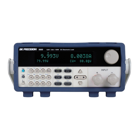
Front Panel Description
Rear Panel Overview
Rear Panel Description
Display Overview
Display Description
2 Getting Started
Input Power and Fuse Requirements
Input Power
Fuse Requirements
Fuse Replacement
Input Connections
Preliminary Check
Self-Test Errors
Input Check
Check Model and Firmware Version
3 Front Panel Operation
Menu Options
System Menu
Config Menu
How to Navigate the Menu
Configure Operation Modes (CC/CV/CR/CW)
Constant Current (CC) Mode
Constant Voltage (CV) Mode
Constant Resistance (CR) Mode
Constant Power (CW) Mode
Setting CC, CV, CR, CW Mode
SYSTEM Menu
Restore Factory Default Settings
Configure Power-On State
Load on Knob
Configure Trigger Source
Save/Recall Instrument Settings
Display Input on Timer
Remote Interface Setup
CONFIG Menu
Von Operation
Configure Protection Settings
Configure Timed Input
Measurement Configurations
CR LED Function
Remote Sense
External Analog Control and Monitor
Short Operation
Transient Operation
Continuous
Pulse
Toggle
List Operation
Configure List
Run List
Battery Test Function
Test Operations
Automatic Test Function
OCP Test Function
OPP Test Function
Key Lock
4 Remote Operation
Interface Connection
Gpib
Usbtmc
Remote Commands
5 Troubleshooting Guide
General
Remote Control
6 Specifications
Supplementary Characteristics
7 Calibration
Index
Advertisement
Quick Links
1
Constant Current (CC) Mode
2
Calibration
Download this manual
See also:
Programming Manual
Model: 8600, 8601, 8602, 8610, 8612, 8614, 8616, 8620, 8622,
8624, and 8625
Programmable DC Electronic Loads
USER MANUAL
Table of
Contents
Previous
Page
Next
Page
1
2
3
4
5
Advertisement
Table of Contents
Need help?
Do you have a question about the 8600 and is the answer not in the manual?
Ask a question
Questions and answers
Related Manuals for BK Precision 8600
Laboratory Equipment BK Precision 8600 Series Programming Manual
(81 pages)
Test Equipment BK Precision 8600/B User Manual
Programmable dc electronic loads (103 pages)
Test Equipment BK Precision 8500 User Manual
8500 series dc electronic loads (76 pages)
Test Equipment BK Precision 8500 Series Instruction Manual
300w dc electronic load (68 pages)
Test Equipment BK Precision 881 Instruction Manual
In-circuit esr & dcr cap tester (11 pages)
Test Equipment BK Precision 8610 User Manual
Programmable dc electronic loads (107 pages)
Test Equipment BK Precision 8612 User Manual
Programmable dc electronic loads (107 pages)
Test Equipment BK Precision 8614 User Manual
Programmable dc electronic loads (107 pages)
Test Equipment BK Precision 8500B Series User Manual
Programmable dc electronic loads (56 pages)
Test Equipment BK Precision 8500B Series Programming Manual
Programmable dc electronic loads (63 pages)
Test Equipment BK Precision BK8510B User Manual
Programmable dc electronic loads (58 pages)
Test Equipment BK Precision 570A Operator's Manual
Handheld linear ic tester (21 pages)
Test Equipment BK Precision 889CS Manual
Bench lcr/esr meter with component tester (35 pages)
Test Equipment BK Precision 8614/B User Manual
Programmable dc electronic loads (103 pages)
Test Equipment BK Precision 4040A Instruction Manual
20 mhz sweep/function generator with frequency counter (49 pages)
Test Equipment BK Precision 1403A Service Manual
(41 pages)
This manual is also suitable for:
8602
8610
8612
8614
8616
8620
...
Show all
8624
8622
8625
8601
Table of Contents
Print
Rename the bookmark
Delete bookmark?
Delete from my manuals?
Login
Sign In
OR
Sign in with Facebook
Sign in with Google
Upload manual
Upload from disk
Upload from URL


Need help?
Do you have a question about the 8600 and is the answer not in the manual?
Questions and answers