
Related Manuals for Srne HEBP4880U200-Pro


Summary of Contents for Srne HEBP4880U200-Pro
- Page 1 File version: V1.0 USER MANUAL Solar Hybrid Inverter HEBP4880U200-Pro HEBP48100U200-Pro HEBP48120U200-Pro...
- Page 2 File version: V1.0 Content 1. Safety ......................................... 4 1.1 How to use this manual ..............................4 1.2 Symbols in this manual ..............................4 1.3 Safety instruction ...................................4 2. Production Instructions .................................5 2.1 Instructions ................................... 5 2.2 Features ....................................5 2.3 System connection diagram ............................6 2.4 Production Overview .................................
- Page 3 File version: V1.0 6.5 CAN port ....................................53 6.6 External CT port .................................. 54 6.7 Dry contact ................................... 55 7. Fault and Remedy ..................................56 7.1 Fault code ................................... 56 7.2 Troubleshooting ................................59 8. Protection and Maintenance ..............................61 8.1 Protection features ................................
- Page 4 File version: V1.0 1. Safety 1.1 How to use this manual • This manual contains important information、guidelines、operation and maintenance for the following products HEBP Series :4880U200-Pro,48100U200-Pro,48120U200-Pro • The manual must be followed during installation and maintenance 1.2 Symbols in this manual Symbol Description DANGER indicates a hazardous situations which if not avoided will result in death...
- Page 5 File version: V1.0 2. Production Instructions 2.1 Instructions HEBP series is a new type of solar energy storage inverter control inverter integrating solar energy storage & utility charging and energy storage, AC sine wave output. It adopts DSP control and features high response speed, reliability, and industrial standard through an advanced control algorithm.
- Page 6 File version: V1.0 2.3 System connection diagram The diagram below shows the system application scenario of this product. A complete system consists of the following components: PV modules: converts light energy into DC energy, which can be used to charge the battery via an inverter or directly inverted into AC power to supply the load.
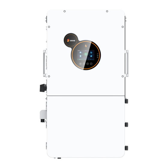
- Page 7 File version: V1.0 2.4 Production Overview LED Indicators Grid terminals(L1+L2) LCD screen Neutral Busbar Grounding l Busbar Generator input terminal External CT port (L1+L2) WIFI port 1 BMS RS485 port Dry contact BMS CAN port USB-A port USB-B port Battery negative Parallel port B Battery positive Parallel port A...
- Page 8 File version: V1.0 2.5 Dimension drawing...
- Page 9 File version: V1.0 3. Installation 3.1 Select the mount location HEBP series can be used outdoors (protection class IP65). Please consider the followings before selecting the location: Choose the solid wall to install the inverter Mount the inverter at eye level ...
- Page 10 File version: V1.0 3.2 Pack list Picture Description Quantity inverter 1pcs Wallhanger 2pcs M8*60 Expansion bolts used to Secure the wall- 4pcs mount bracket To the wall 4mmHex head 1pcs screwdriver Parallel communication 1pcs cable 2pcs WIFI logger 1pcs...
- Page 11 File version: V1.0 User manual 1pcs The warranty card 1pcs Quality Certificate 1pcs Outgoing inspection 1pcs report...
- Page 12 File version: V1.0 3.3 Mount the inverter Step1:Determine the positions for drilling holes,ensure the position of holes are level,then mark them with a marker pen,use the hammer drill to drill holes on the wall.Keep the hammer drill perpendicular to the wall,do not shake when drilling, so as not to damage the wall.If the error of the hole is too big,you need to reposition.
- Page 13 File version: V1.0 3.4 Remove the terminal cover & anti insect net Using a screwdriver, remove the fan shroud and open the cover. Removable fan cover for cleaning ○ NOTICE When using the device in areas with poor air quality, the fan cover is easily blocked by air particles, please ...
- Page 14 4.2 Cable & circuit breaker requirement PV INPUT Model No. of PV Cable Diameter Max. PV Input Current Circuit Breaker Spec 6mm²/ 10 AWG 2P-25A HEBP4880U200-Pro 6mm²/ 10 AWG 2P-25A 6mm²/ 10 AWG 2P-25A HEBP48100U200-Pro 6mm²/ 10 AWG 2P-25A 6mm²/ 10 AWG...
- Page 15 File version: V1.0 AC INPUT Model Schema Cable Diameter Circuit Breaker Spec 13mm²/6AWG HEBP4880U200-Pro 3P-63A (L1/L2/N) 13mm /6AWG HEBP48100U200-Pro 3P-63A (L1/L2/N) 13mm /6AWG HEBP48120U200-Pro 3P-63A (L1/L2/N) GENERATOR INPUT Model Schema Cable Diameter Circuit Breaker Spec 13mm²/6AWG HEBP4880U200-Pro 3P-63A (L1/L2/N) 13mm²/6AWG...
- Page 16 File version: V1.0 ○ NOTICE • PV Input, AC Input, AC Output, Generator Input 1.Use a stripper to remove the 6~8mm insulation of the cable 2.Fixing a ferrule at the end of the cable. (ferrule needs to be prepared by the user) •...
- Page 17 File version: V1.0 4.3 GRID & LOAD & GEN connection Connect the live,neutral and ground wires according to the cables’ position and order shown in the diagram below. △ DANGER Before connecting AC inputs and outputs, the circuit breaker must be opened to avoid the risk of •...
- Page 18 File version: V1.0 4.4 Battery Connection Connect the positive and negative cable of the battery according to the diagram below △ DANGER • Before connecting battery, the circuit breaker must be opened to avoid the risk of electric shock and must not be operated with electricity. •...
- Page 19 File version: V1.0 4.5 PV connection Connect the positive and negative wires of both PVs in the cable locations and sequence shown in the diagram below. △ DANGER Before connecting the PV, the circuit breaker must be disconnected to avoid the risk of electric •...
- Page 20 File version: V1.0 4.6 Dry contact connection Use a small screwdriver to push back the direction indicated by the arrow, then insert the communication cable into the dry junction port. (Communication cable diameter 0.2~1.5mm²) 4.7 Grounding connection Please make sure the grounding terminal connect to the Grounding Bar. The grounding cable should have a diameter of not less than 4 mm²...
- Page 21 File version: V1.0 4.8 Final assembly After ensuring that the wiring is reliable and the wire sequence is correct, install the terminal protection cover in place. • Step 1 : Close the circuit breaker of the battery. • Step 2:Press the rocker switch on the bottom of inverter, the screen and indicators light up to indicate that the inverter has been activated.
- Page 22 File version: V1.0 4.GRID wiring: Parallel connection in single phase: ensure L-to-L, N-to-N and PE-to-PE connection for all solar storage inverters, and that the connection is correct with the same wiring length and line diameter before power on, so as to avoid the abnormal operation of parallel system output caused by wrong connection. Meanwhile, it is not allowed to have multiple different AC source inputs to avoid damage to the external equipment of the inverter.
- Page 23 File version: V1.0 The wiring diagram is shown below: Up to six inverters parallel...
- Page 24 File version: V1.0 4.9.4 Three-phase parallel connection 2 inverters connected in parallel to form a three-phase output (three-phase unbalanced) P1 machine setting: Parallel mode select "Three phase A", grid type select "Three Phase", when output phase voltage select "120V , the output L1-L2 voltage is 208V, L1-N voltage is 120V, L2-N voltage is 120V. P2 machine setting: Parallel mode select "Three phase B", grid type select "Three Phase", when the output phase voltage select "120V", then the output L1-L2 voltage is 208V, L1-N voltage is 120V, L2-N voltage is 120V.
- Page 25 File version: V1.0 (2)3 or 6 inverters in parallel to form a three-phase output (three-phase balanced) P1 machine setting: Parallel mode select "Three phase A", grid type select "Three Phase", when output phase voltage select "120V , the output L1-L2 voltage is 208V, L1-N voltage is 120V, L2-N voltage is 120V.
- Page 26 File version: V1.0 P2 machine setting: Parallel mode select "Three phase B", grid type select "Three Phase", when the output phase voltage select "120V", then the output L1-L2 voltage is 208V, L1-N voltage is 120V, L2-N voltage is 120V. P3 machine setting: Parallel mode select "Three phase C", grid type select "Three Phase", when output phase voltage select "120V", then output L1-L2 voltage is 208V, L1-N voltage is 120V, L2-N voltage is 120V.
- Page 27 File version: V1.0...
- Page 28 File version: V1.0...
- Page 29 File version: V1.0 5. Operating Instructions 5.1 Operation interface The operation interface of the inverter includes 1 LCD display, 3 LED indicators, and 4 physical buttons. 5.1.1Physical buttons Buttons Functional description Enter or exit the Settings screen Jump to previous page Jump to the next page Confirm or enter the selected options 5.1.2 LED indicators...
- Page 30 File version: V1.0 5.1.3 LCD screen The main page displays elements: Icon Description Icon Description Solar panel Load Battery Grid or Generator Home page button Inverter History data Setting Local time The buzzer On/Off Indicates that the machine is The energy direction currently in energy-saving mode UPS load HOME load...
- Page 31 File version: V1.0 5.1.4 Real time data 5.1.4.1 System information Click the inverter icon on the LCD home screen to view the system information of the device. The following information is displayed: System information device state SN code MCU1 software version Compiled version LCD version Rated power...
- Page 32 File version: V1.0 5.1.4.4 Grid or generator information Click the grid icon on the LCD home screen to view the grid or generator information. The following information is displayed: Grid or generator information L1 phase voltage L2 phase voltage L1 phase current L2 phase current L1 phase active power (Positive is L2 phase active power (Positive is to sell...
- Page 33 File version: V1.0 5.1.5 Historical information Click the "History" icon at the bottom of the main page to view historical battery statistics and historical fault information. 5.1.5.1 Electricity statistics for the day Today The amount of battery charge today The load consumes electricity today The amount of battery discharge The amount of charge from grid today...
- Page 34 File version: V1.0 5.2 Parameter setting Click the "Settings" button in the menu bar below the main page to enter the Settings page, which contains five Settings: basic Settings, working mode Settings, battery Settings, grid-connected Settings and advanced Settings. 5.2.1 Basic setting 5.2.1.1 display setup 1.
- Page 35 File version: V1.0 5.2.2 Operating mode setting 5.2.2.1Basic mode of operation 1.Hybrid grid mode: Select the device to work in grid-connected power generation mode or anti-flow mode. "on grid" means PV energy can be connected to the grid to sell electricity, ...
- Page 36 File version: V1.0 mode. "Battery to ups load" means that the battery discharge power is only supplied to the ups load, and the discharge power is less than or equal to the ups load power. "Battery to home load" means that the battery discharge power is only supplied to the ups load and Home load, ...
- Page 37 File version: V1.0 greatest extent. 1. Timed charging enable: Select whether to enable the timed charging feature. 2. Timed discharging enable: Select whether to enable the timed discharging feature. 3. Start time: Sets the start time of the timing period. 4.
- Page 38 AOGUAN 485 protocol OLITER OULITE 485 protocol CFGE 485 protocol Sunwoda XINWANGDA 485 protocol Dyness DAQIN 485 protocol SRNE 485 protocol Pylon tech 485 protocol FOX ESS 485 protocol Xinyi energy 485 protocol PowMr 485 protocol GOTION GUOX 485 protocol...
- Page 39 File version: V1.0 charging current parameter set through the screen as the current limit value for battery charging. "BMS" means reading the maximum charging current limit given by the battery through BMS communication. "Inverter" means that the charging current is limited by using the current limiting logic built into the inverter, this is used for those battery BMS that do not have a current limiting function according to the SOC, the current limiting logic is shown in the following table: Charge current limit value...
- Page 40 File version: V1.0 is effective when the BMS communication is normal. The second Settings page is about battery discharge parameters, containing the following parameters: Batt. volt. stop dischg. : Set the battery stop discharge voltage in the hybrid mode, when the battery voltage is ...
- Page 41 File version: V1.0 5.2.4 Grid parameter setting: You will need to enter a password to access this page, the default password is "0000". The parameter page has grid-connected basic function Settings, grid enter service Settings, grid protection Settings and other function Settings.
- Page 42 File version: V1.0 5.2.4.2 Grid enter service Settings(This setting is not recommended to be changed by customers) This page is used to set the voltage frequency of connecting to the grid. According to the requirements of the grid connection standard, the voltage and frequency of the grid must be within the set parameter range before the grid connection can be started, otherwise the...
- Page 43 File version: V1.0 Volt-Var curve enable: This function regulates the grid-connected reactive power of the inverter according to the grid voltage. Watt-Var curve enable: This function is to regulate the reactive power according to the active power output of ...
- Page 44 File version: V1.0 and charging, and if it is in the off-grid state at this time, the output will stop. Power saving mode: Choose whether to enable power saving mode. In the off-grid state, the inverter will enter the energy-saving mode after 5 minutes in the no-load state (load less than 25Watt). The output voltage will be turned off, and the load will be detected for 10 seconds every 3 minutes.
- Page 45 File version: V1.0 are sensitive to voltage, such as fixed-frequency air conditioners. Try selecting "Voltage sensitive load". 3. If the local power grid has frequent power outages, and the load is connected to the motor load of the pump. Try selecting "Pump type load".
- Page 46 File version: V1.0 5.3 Recommended Settings 5.3.1 Peak and valley electric charges Applicable scene: The grid is relatively stable and has peak and valley electricity prices. It is expected to realize economic benefits or reduce electricity costs through the price difference. Do you Grid Hybrid grid...
- Page 47 File version: V1.0 How this scenario works: (1) The photovoltaic energy is preferentially supplied to the load, and the residual energy after meeting the load power is used to charge the battery. (2) When the PV power is insufficient to supply the load or there is no PV, the battery discharges to replenish the energy.
- Page 48 File version: V1.0 (3) After the PV energy meets the charging power, the residual energy is provided to the load. (4) When the power grid outage, the device switches to the battery inverter output, if there is PV, PV and battery hybrid inverter output, PV energy priority.
- Page 49 File version: V1.0 5.4 Battery parameter • Lead-acid battery Battery type Sealed lead acid Flooded lead acid Gel lead acid battery User-defined battery battery Parameters Overdisconnect Voltage 40~60V Boost charging voltage 57.6V 56.8V 57.6V (can be set) Undervoltage alarm 40~60V voltage (can be set) Undervoltage...
- Page 50 File version: V1.0 • Li-ion batter Battery type Ternary User-defined Parameters Overdisconnect Voltage 40~60V Boost charging voltage 53.2V 57.6V 56.8V 53.2V 49.2V (can be set) Undervoltage alarm 40~60V 43.6V 46.8V 49.6V 46.4V 43.2V voltage (can be set) Undervoltage disconnect 40~60V 38.8V 48.8V 45.6V...
- Page 51 File version: V1.0 6. Communication 6.1 Overview External CT port Parallel port B WIFI port 1 Parallel port A BMS RS485 port Dry contact BMS CAN port USB-A port USB-B port 6.2 USB-B port USB2.0 printer The user can read and modify device parameters through this port by using the host software. Please contact us for the host software installation package if you require one.
- Page 52 File version: V1.0 6.3 WIFI The WIFI port is used to connect to the Wi-Fi/GPRS data acquisition module, which allows users to view the operating status and parameters of the inverter through the cell phone APP. Only can connect one port WIFI port 1: RJ45 Definition...
- Page 53 File version: V1.0 6.4 RS485 port The RS485 port is used to connect to the BMS of Liion battery. RJ45 定义 Pin 1 Pin 2 Pin 3 Pin 4 CANH Pin 5 CANL Pin 6 Pin 7 RS485-A Pin 8 RS485-B 6.5 CAN port RJ45...
- Page 54 File version: V1.0 6.6 External CT port 1. Length of CT Output Line Wrap:4m 2. Normally The CT direction is “to inverter” 3. Current transformer (CT) dimensions:(mm) laser engraving fuse side...
- Page 55 File version: V1.0 6.7 Dry contact Dry contact port with 3 functions: 1. RSD power supply 2. Temperature sampling (reserved) 3. Generator remote start/stop Function Description RSD power supply PIN 1 is GND,PIN 2 is RSD 12V+ Temperature sampling Pin 1 & Pin 5 can be used for battery temperature sampling compensation. (reserved)...
- Page 56 File version: V1.0 7. Fault and Remedy 7.1 Fault code Whether it affects the output or Fault code Fault name Description BatVoltLow Battery undervoltage alarm. Battery discharge average current BatOverCurrSw overcurrent (software protection). BatOpen Battery not-connected alarm Battery undervoltage stop discharge BatLowEod alarm.
- Page 57 File version: V1.0 Positive and negative bus voltage Busdiff imbalance BusShort Busbar short circuit Inverter AC output backfeed to bypass Rlyshort AC output LinePhaseErr Utility input phase error BusVoltLow Low bus voltage protection Alarm given when battery capacity rate BatCapacityLow1 is lower than 10% (setting BMS to enable validity).
- Page 58 File version: V1.0 Grid DC current over Grid standard un init Low insulation PV1+, PV2+ and PV- abnormally low resistance fault impedance to ground. Leakage current System leakage current exceeds limit. overload fault BMSComErr BMS communication failure BMSUnderTem BMS alarm battery low temperature. BMS alarm battery over temperature.
- Page 59 File version: V1.0 7.2 Troubleshooting Remedy Fault code Faults Check if the battery switch or PV switch is closed; Display No display on the screen whether the switch is in the "ON" state; press any button on the screen to exit the screen sleep mode Check that the battery voltage does not exceed the Battery overvoltage protection value.
- Page 60 File version: V1.0 Incorrect device serial number setting. 【44】 Serial number error There is a device in the parallel system with the wrong 【45】 Parallel mode error parallel mode setting. Check that the grid voltage is within the normal range, if 【49】...
- Page 61 File version: V1.0 8. Protection and Maintenance 8.1 Protection features Protection Feature Instruction When the charging current or power of the PV array configured exceeds PV current limiting the PV input rated value, the inverter will limit the input power and protection charge at the rated.
- Page 62 File version: V1.0 After triggering the overload protection the inverter will resume Inverter over-load output after 3 minutes, 5 consecutive overloads will switch off the protection output until the inverter is restarted. AC output reverse Prevents AC back flow from the battery inverter to the bypass AC input. Bypass over-current Built-in AC input over-current protection circuit breaker protection...
- Page 63 File version: V1.0 8.2 Maintenance To maintain optimum and long-lasting working performance, we recommend that the following items are checked twice a year. 1.Ensure that the airflow around the inverter is not blocked and remove any dirt or debris from the radiator. 2.
- Page 64 File version: V1.0 9. Datasheet Settab MODEL HEBP4880U200-Pro HEBP48100U200-Pro HEBP48120U200-Pro Inverter output @240V 12000W Rated Output Power 8800W 10,000W @208V 10400W Max. Peak Power 1.5 times rated power Rated Output Voltage 120/240Vac(Split-phase) 120/208V(Three-phase) √ @240V 36.6A @240V 41.7A Output voltaege error @208V 42.3A...
- Page 65 File version: V1.0 MPPT Tracking Efficiency 99.9% Max Efficiency 97.5% CEC Efficiency 96.5% Basic data Dimensions 840*440*260mm Weight 48kg Protection Degree IP65 Operating Temperature -25~60℃,>45℃ derated Range Noise <60dB Self-comsumption <100W Cooling Method Heat sink + intelligent fan cooling Communication Communication port RS485 / CAN / USB / Dry contact √...
Need help?
Do you have a question about the HEBP4880U200-Pro and is the answer not in the manual?
Questions and answers