Table of Contents
Advertisement
Quick Links
Advertisement
Table of Contents

Related Manuals for Srne HESP4880SH3


Summary of Contents for Srne HESP4880SH3
- Page 1 USER MANUAL Solar Hybrid Inverter HESP4880SH3 HESP48100SH3 HESP48120SH3 V1.1...
-
Page 2: Table Of Contents
CONTENTS 1. Safety ...............................1 1.1 How to use this manual ..............................1 1.2 Symbols in this manual ..............................1 1.3 Safety instructio .................................1 2. Production Instructions ......................... 2 2.1 Instructions ..................................2 2.2 Features ....................................2 2.3 System connection diagram ............................3 2.4 Production overview ................................ 4 2.5 Dimension drawing ................................ - Page 3 6.2 USB-1 port ..................................40 6.4 RS485 port ..................................41 6.5 CAN port ....................................42 6.6 USB-2 port ..................................42 6.7 External CT port ................................43 6.8 Dry contact port ................................44 7.Fault and Remedy ..........................45 7.1 Fault code ..................................45 7.2 Troubleshooting ................................49 8.
-
Page 4: Safety
1. Safety 1.1 How to use this manual • This manual contains important information、guidelines、operation and maintenance for the following products : HESP series 4880SH3, 48100SH3, 48120SH3 • This manual must be followed during installation, use and maintenance. 1.2 Symbols in this manual Symbols Description DANGER indicates a hazardous situations which if not avoided will result in... -
Page 5: Production Instructions
2. Production Instructions 2.1 Instructions HESP SH3 series is a new type of solar energy storage inverter control inverter integrating solar energy storage & utility charging and energy storage, AC sine wave output. It adopts DSP control and features high response speed, reliability, and industrial standard through an advanced control algorithm. -
Page 6: System Connection Diagram
2.3 System connection diagram The diagram below shows the system application scenario of this product. A complete system consists of the following components: PV modules:converts light energy into DC energy, which can be used to charge the battery via an inverter or directly inverted into AC power to supply the load. -
Page 7: Production Overview
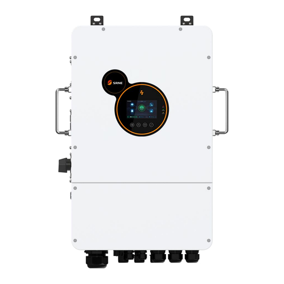
2.4 Production overview LED indicator LCD screen Physical key Generator terminals PV1 terminals PV2 terminals (L1+L2+L3+N) Load terminals Grid terminals USB-1 (L1+L2+L3+N) (L1+L2+L3+N) WIFI 485 port CAN port DRMS Grid current(CT) Dry contact Parallel communication Parallel communication A USB-2 B port port Battery terminal PV circuit breaker... -
Page 8: Dimension Drawing
2.5 Dimension drawing... -
Page 9: Installation
3. Installation 3.1 Select the mount location HESP series can be used outdoors (protection class IP65). Please consider the followings before selecting the location: • Choose the solid wall to install the inverter. • Mount the inverter at eye level. •... -
Page 10: Mount The Inverter
3.2 Mount the inverter Punch 4 mounting holes in the wall with an electric drill according to the specified size, and insert 4 M8*60 expansion screws above. 3.3 Remove terminal protection cover and dust screen Using a screwdriver, remove the terminal protection cover and dust screen. terminal protection cover ○... -
Page 11: Connection
4. Connection 4.1 Three-phase mode Items Description HESP series SH3 model Applicable models 200~240Vac, 230Vac default AC output phase voltage (L-N) ○ NOTICE The user can change the output phase mode and output voltage through the setup menu, please read chapter 5.2 for details. The output voltage corresponds to item [38] of the parameter setting, and the ... -
Page 12: Cable & Circuit Breaker Requirement
4.2 Cable & circuit breaker requirement • PV input Max. PV Input Circuit Models Cable Diameter Current Breaker Spec HESP4880SH3 5mm²/ 10 AWG 2P-25A HESP48100SH3 5mm²/ 10 AWG 2P-25A HESP48120SH3 5mm²/ 10 AWG 2P-25A • GRID Max. Phase Circuit Models... - Page 13 • Battery Models Cable Diameter Max. Current Circuit Breaker Spec HESP4880SH3 ² / 0 AWG 180A 2P-200A 53mm HESP48100SH3 ² / 00 AWG 67mm 220A 2P-250A HESP48120SH3 ² / 00 AWG 260A 2P-300A 67mm • LOAD Max.phase Circuit Models Output Mode...
-
Page 14: Ac Input & Output Connection
4.3 AC input & output connection Connect the live, neutral and ground cables in the position and order of the cables as shown in the diagram below. △ DANGER • Before connecting the AC input and output, the circuit breaker must be disconnected to avoid the risk of electric shock and must not be operated with electricity. -
Page 15: Battery Connection
4.4 Battery connection Connect the positive and negative cable of the battery according to the diagram below. DANGER △ • Before connecting the battery, the circuit breaker must be disconnected to avoid the risk of electric shock and must not be operated with electricity. •... -
Page 16: Pv Connection
4.5 PV connection Connect the positive and negative wires of the two strings of PV according to the diagram below. △ DANGER • Before connecting the PV, the circuit breaker must be disconnected to avoid the risk of electric shock and must not be operated with electricity. •... -
Page 17: Grounding Connection
4.7 Grounding connection Make sure that the earth terminal is securely connected to the grounding busbar. • Grounding wire shall be not less than 4 mm² in diameter and as close as possible to the earthing point. 4.8 Final assembly After ensuring that the wiring is reliable and the wire sequence is correct, restore the terminal protection cover to its original position. -
Page 18: Parallel Wiring
4.9 Parallel wiring 4.9.1 Parallel operation 1. The parallel operation supports up to six solar storage inverters. 2. When using the parallel function, it is necessary to connect the parallel communication cable in a correct and reliable manner. See the figure blow for the communication cable (packaging accessory): Parallel communication cable*1 4.9.2 Cautions for parallel connection Warning:... -
Page 19: Schematic Diagram Of Parallel Connection
N-to-N and PE-to-PE. The L lines of all inverters in the same phase shall be connected together, but the AC output L lines of different phases shall not be connected together. Other cautions are the same as those for single-phase parallel connection. 5. - Page 20 a) Two units connected in parallel:...
- Page 21 b) Three units connected in parallel:...
- Page 22 c) Four units connected in parallel: d) Five units connected in parallel:...
- Page 23 e) Six units connected in parallel:...
-
Page 24: Operation
5. Operation 5.1 Operation and display panel The operation and display panel below includes 1 LCD screen, 3 indicators, 4 touchable keys. Keys • Keys Description To enter/exit the setting menu To lastselection To next selection To confirm/enter the selection in setting menu LED Indicators •... - Page 25 Display panel • Icon Description Description Icon Solar panel Load Battery Grid or Generator Inverter is Home page Working History data Setting Local time The buzzer is slient BMS communicate status The enery direction...
- Page 26 • View real-time data On the LCD home screen, click the inverter icon, battery icon, mains icon, load icon and photovoltaic icon to view the real-time data of the machine. System data Item Item Machine state MCU1 version Min version number LCD version Rated power MCU2 version...
- Page 27 L1 Current L2 Current L1 Active power L2 Active power L1 Apparent power L2 Apparent power L1 Home Load Power L2 Home Load Power L1 Secondary Load Apparent Power L2 Secondary Load Apparent Power L3 Voltage L3 Apparent power L3 Current L3 Home Load Power L3 Active power L3 Secondary Load Apparent Power...
-
Page 28: Setting
5.2 Setting Operating instructions: Click on the settings in the menu bar at the bottom of the screen to enter the setup interface, including the basic settings, work mode setup, battery setup,on grid setup, advanced setup of the five major setup items 5.2.1 Basic Setup 5.2.1.1 Display Setup Parameter Meaning... - Page 29 5.2.1.2.Time Setup 5.2.1.3.Password Setting(Password is required to access the Grid Settings and Advanced Settings) Default password is "00000". Password setting value range: 0-65535...
- Page 30 5.2.2 Work Mode Setup 5.2.2.1.Work Mode Home Load: connected to the GRID port of the machine, requires external CT for monitoring. Ups Load: connected to the LOAD port of the machine. Parameter Meaning Option Description On grid Direct grid connection of excess PV energy Ups load backflow prevention, photovoltaic or battery energy Limit Power to ups load is only for the ups load, excess energy will not be connected to...
- Page 31 5.2.2.2.Peak Shaving Parameter Meaning Description Time charging/ Select whether to turn on timed charging and discharging discharging enable Start/End Time Setting the time period for timed charging and discharging Setting the battery charging cut-off SOC value and the cut-off SOC value for Stop SOC discharging during the timed charging and discharging time period (during BMS communication)
- Page 32 1 : PACE-PACEEX 2 : RUDA-Ritar 3 : AOGUAN-=ALLGRAND BATTERY 4 : OULITE-OLITER BMS comm.protocol 5 : CEF-CHANGFENG TECNOLOGY 6 : XINWANGDA -SUNWODA 7: DAQIN -DAKING 8 : WOW-SRNE 9: PYL-PYLONTECH 10 : MIT-FOXESS 11: XIX-XYE 12: POL-POWERMR 13: GUOX-Gotion 14: SMK-SMK 15: VOL-WEILAN 16:UZE-YUZE Battery max.curr.dcharge...
- Page 33 5.2.3.2.Battery Manage Parameter Meaning Description Maximum chg.voltage When the battery is charging, the voltage reaches the value to stop charging When the battery is fully charged, the inverter stops charging and resumes charging when Batt. Recharging voltage the battery voltage falls below this voltage value. Battery curr.
- Page 34 5.2.3.2.BMS date(When the battery communicate with inverter) Check the data that battery BMS uploade to inverter 5.2.4 On grid setup To enter this setting, you need to enter the password set by the user, the default password is "00000". 5.2.4.1.Basic...
- Page 35 Parameter Meaning Description Eu general:EN50549-1 VDE-ARN-4105 Grid Standard German: Other regions:GNL Grid Frequency Selection of local grid frequency,50Hz/60Hz CT ratio When connecting an external CT, enter the ratio on the CT specification. Sell power Max On grid power Maximum power drawn from the grid. If the grid charging power + load power exceeds this Buy power Max setting, the machine reduces the charging power.
- Page 36 Parameter Meaning Description Enter Service enable Grid-connect enable setting (on by default) Connect Voltage Low Grid-connected low voltage protection voltage Connect Frequency Low Grid-connected low-frequency protection points Connect Voltage High Grid-connected high-voltage protection voltage Connect Frequency High Grid-connected high-frequency protection points Normal connect delay time Grid normal connection, grid connection delay time Normal connect Power Ramp Rate...
- Page 37 5.2.5 Advance Setup To enter this setting, you need to enter the password set by the user, the default password is "00000". 5.2.5.1. Generator Parameter Meaning Description Max charging current by gen. Maximum battery charging current during generator charging Generator rate power Setting the power of the generator up to the rated power of the inverter Generator charging enable Setting whether the generator is charged or not...
- Page 38 5.2.5.2. Other Parameter Meaning Description PE-N connect enable Enable automatic switching of PE-N connections PV Riso check enable Enable PV insulation impedance detection Leakage curr. protection enable Enable leakage current protection BMS comm.error stop When the BMS communication is fault, the inverter stop output After turning on the energy-saving mode, if the load is empty or less than 25W, the Power saveing mode inverter output will be shut down after a delay of 5min;...
- Page 39 Parameter Meaning Description Load type According to the load that you have connected, select the load type When the inverter soft start, adjust the current coefficient(This setting doesn’t Inverter current limiting coefficient recommend to be changed by the customer) 5.2.5.3. Restart Parameter Meaning Description Restore Factory Settings...
-
Page 40: Time-Slot Charging/Discharging Function
5.5 Time-slot charging/discharging function HESP H3 series is equipped with time-slot charging / discharging function, users can set different charging/discharging time slots according to the local peak and valley electricity price, so as to make efficient use of utility power and PV energy. When the utility price is expensive, the battery inverter can be used to supply power to the loads. -
Page 41: Battery Parameter
5.6 Battery parameter • Lead-acid battery Battery type Sealed lead Gel lead Flooded lead User-defined acid battery acid battery acid battery Adjustable (USE) Parameters (SLD) (GEL) (FLD) Overvoltage disconnection voltage Battery fully charged √ recovery point Boost charge voltage 40~60V √... - Page 42 • Li-ion battery Battery type Ternary Ternary LFP (L16) Adjustable (N13) (N14) (L15) (L14) Parameters Overvoltage disconnection voltage Battery fully charged 50.4V 54.8V 53.6V 50.4V 47.6V √ recovery point Equalizing charge √ voltage Boost charge voltage 53.2V 57.6V 56.8V 53.2V 49.2V √...
-
Page 43: Communication
6. Communication 6.1 Overview USB-B port WIFI port RS485 port CAN port DRMS port CT port Dry contact USB-A port 6.2 USB-1 port The user can read and modify device parameters through this port by using the host software. Please contact us for the host software installation package if you require one... -
Page 44: Rs485 Port
6.3 WIFI port The WIFI port is used to connect to the Wi-Fi/GPRS logger module, which allows users to view the operating status and parameters of the inverter via mobile phone APP. RJ45 Definition Pin 1 Pin 2 Pin 3 Pin 4 Pin 5 Pin 6... -
Page 45: Can Port
6.5 CAN port RJ45 Definition The CAN port is used to connect to the Pin 1 BMS of Liion battery . Pin 2 Pin 3 Pin 4 CANH Pin 5 CANL Pin 6 Pin 7 Pin 8 6.6 USB-2 port It is used to updated the screen firmware 6.7 DRMS(Only Australia) RJ45 socket... -
Page 46: External Ct Port
Definitio RJ45 6.7 External CT port Pin 1 CT1+ Pin 2 CT1- Pin 3 Pin 4 CT2+ Pin 5 CT2- Pin 6 Pin 7 CT3+ Pin 8 CT3- 1. Split Core Current Transformer (CT) dimension: (mm) 2. Secondary output cable length is 4m. -
Page 47: Dry Contact Port
6.8 Dry contact port Dry contact port with 3 functions: RSD power supply Temperature sampling (reserved) 3. Generator remote start/stop Function Description RSD power supply PIN 1 is GND,PIN 2 is RSD 12V+ Temperature sampling Pin 1 & Pin 5 can be used for battery temperature sampling compensation. (reserved)... -
Page 48: Fault And Remedy
7.Fault and Remedy 7.1 Fault code Whether it affects the Fault code Fault name Description output or 【01】 BatVoltLow Battery undervoltage alarm. Battery discharge average current 【02】 BatOverCurrSw overcurrent (software protection). 【03】 BatOpen Battery not-connected alarm. Battery undervoltage stop discharge 【04】... - Page 49 【17】 InvShort Inverter short-circuit protection. Bussoftfailed 【18】 Bus soft-start failure Buck heat sink over temperature 【19】 OverTemperMppt protection. Inverter AC output with load or AC 【20】 OverTemperInv charging radiator over-temperature protection. 【21】 FanFail Fan blockage or failure fault. 【22】 EEPROM Memory failure.
- Page 50 CAN communication fault in parallel 【34】 CanCommFault operation. Parallel ID (communication address) 【35】 ParaAddrErr setting error. 【36】 Balance currentOC Balance bridge arm overcurrent failure 【37】 ParaShareCurrErr Parallel current sharing fault . Large battery voltage difference in 【38】 ParaBattVoltDiff parallel mode. Inconsistent AC input source in parallel 【39】...
- Page 51 Low insulation PV1+, PV2+ and PV- abnormally low 【56】 resistance fault impedance to ground. Leakage current 【57】 System leakage current exceeds limit. overload fault Check whether the communication line is BMS communication connected correctly and whether [33] is 【58】 error set to the corresponding lithium battery communication protocol.
-
Page 52: Troubleshooting
7.2 Troubleshooting Fault Meaning Causes Remedy Code Check whether the battery air circuit- No power input, or the breaker or PV air circuit-breaker is turned No screen display switch on the bottom of on. Check if the switch is "ON". Press any the unit is not switched on. - Page 53 Manually toggle the fan after powering off Hardware detects fan Fan failure the machine to check for foreign matter failure. blockage. Manually turn off and restart the machine, AC input relay short- if the fault reappears after restarting, you Relay for AC input sticking. circuit need to contact the after-sales service to repair the machine.
-
Page 54: Protection And Maintenance
8. Protection and Maintenance 8.1 Protection function Protection functions Description When the charging current or power of the PV array configured PV input current / power exceeds the PV input rated value, the inverter will limit the input limiting protection power and charge at the rated. - Page 55 Three phase overload logic: After triggering the overload protection, the inverter will resume output after 3 minutes, 5 consecutive overloads will shut down the output until the inverter is restarted. (102%<load<110%):alarm,output shut down after 5 minutes. Inverter over-load (110%<load<125%):alarm, output shut down after 20s. protection (125%<load<200% ):alarm, output shut down after 10s.
-
Page 56: Maintenance
8.2 Maintenance To maintain optimum long-lasting working performance, it is recommended that the following items be checked twice a year. Ensure that the airflow around the inverter is not blocked and remove any dirt or debris from the radiator. Check that all exposed conductors are not damaged by sunlight, friction with other surrounding objects, dry rot, insect or rodent damage, etc. -
Page 57: Datasheet
9. Datasheet MODEL HESP4880SH3 HESP48100SH3 HESP48120SH3 Settable Inverter output Rated Output Power 8000W 10,000W 12000W Max. Peak Power 16000VA 20,000VA 24,000VA Rated Output Voltage 230/400Vac (three-phase) Output voltage error ±5% Load Capacity of Motors Rated AC Frequency 50/60Hz ± 0.3Hz... - Page 58 Max. Generator Charging 100Adc 120Adc 120Adc Current Max. Grid Charging Current 100Adc 120Adc 120Adc Max. Hybrid Charging Current 180Adc 220Adc 260Adc PV input Num. of MPP Trackers Max. PV array power 6000W/6000W 7500W/7500W 9000W/9000W Max. input current 22/22Adc Max.PV Isc 37A/37Adc Max.
- Page 59 Noise <60dB Protection Degree IP65 Cooling Method Heat sink + intelligent fan cooling Self-consumption <130W Dimensions 700*440*260mm Weight 39.2kg Communication port RS485 / CAN / USB / Dry contact External Modules (Optional) Wi-Fi / GPRS...
Need help?
Do you have a question about the HESP4880SH3 and is the answer not in the manual?
Questions and answers