
Subscribe to Our Youtube Channel
Related Manuals for Srne HFP4850S80-145


Summary of Contents for Srne HFP4850S80-145
- Page 1 All-in-one solar charger inverter User Manual Product models: HFP4850S80-145 | HFP4835U80-145 All-in-one solar charge inverter V4.0...
- Page 2 Important safety instructions Please keep this manual for future use. This manual contains all safety, installation and operating instructions for the HFP Series all-in-one solar charge inverter. Please read all instructions and precautions in the manual carefully before installation and use. ...
-
Page 3: Table Of Contents
CONTENTS 1. GENERAL INFORMATION ....................4 1.1 P .................. 4 RODUCT OVERVIEW AND FEATURES 1.2 B ..................5 ASIC SYSTEM INTRODUCTION 1.3 A ....................... 6 PPEARANCE 1.4 D ....................7 IMENSION DRAWING 2. INSTALLATION INSTRUCTIONS ..................8 2.1 I .................... 8 NSTALLATION PRECAUTIONS 2.2 W ............ -
Page 4: General Information
1. General information 1.1 Product overview and features HFP series is a new all-in-one hybrid solar charge inverter, which integrates solar energy storage & means charging energy storage and AC sine wave output. Thanks to DSP control and advanced control algorithm, it has high response speed, high reliability and high industrial standard. -
Page 5: Basic System Introduction
1.2 Basic system introduction The figure below shows the system application scenario of this product. A complete system consists of the following parts: 1. PV module: Convert light energy into DC power, and charge the battery through the all-in-one solar charge inverter, or directly invert into AC power to drive the load. 2. -
Page 6: Appearance
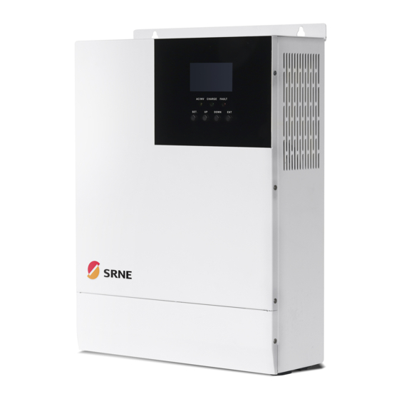
1.3 Appearance RS485-1 ① ⑩ Overload protector communication port ② ⑪ ON/OFF rocker switch Dry contact port ③ ⑫ AC input port Cooling fan ④ ⑬ AC output port Battery port ⑤ ⑭ Grounding screw hold Cooling fan ⑥ ⑮ RS485-2 communication port PV port Current sharing port... -
Page 7: Dimension Drawing
1.4Dimension drawing All-in-one solar charge inverter V4.0... -
Page 8: Installation Instructions
2. Installation instructions 2.1 Installation precautions Please read this manual carefully prior to installation to familiarize yourself with the installation steps. Be very careful when installing the battery. Wear safety goggles when installing a lead-acid liquid battery. Once coming into contact with the battery acid, rinse with clean water timely. Do not place metal objects near the battery to prevent short-circuit of the battery. -
Page 9: Wiring Specifications And Circuit Breaker Selection
Recommended air switch or Models wiring diameter input current circuit breaker type 10mm 2 /7AWG HFP4850S80-145 2P—63A 10mm 2 /7AWG HFP4835U80-145 2P—63A Note: The voltage in series shall not exceed the maximum PV input open circuit voltage. Refer to the table below for recommended AC input wire diameter and switch: ... - Page 10 Models battery wiring battery charge switch or circuit diameter discharge current breaker type current 30mm 2 /2AWG HFP4850S80-145 125A 140A 2P—160A 25mm 2 /3AWG HFP4835U80-145 120A 2P—140A Recommended AC output wiring specifications and circuit breaker selection Recommended Rated inverter...
-
Page 11: Installation And Wiring
2.3 Installation and wiring Installation steps:: Step 1: Determine the installation position and the space for heat dissipation. Determine the installation position of the all-in-one solar charge inverter, such as wall surface; when installing the all-in-one solar charge inverter, ensure that there is enough air flowing through the heat sink, and space of at least 200m to the left and right air outlets of the inverter shall be left to ensure natural convection heat dissipation. - Page 12 Step 2: Remove the terminal cover Step3: Wiring AC input / output wiring method: ① Prior to AC input/output wiring, disconnect the external circuit breaker and confirm that the wire used is thick enough. Please refer to Section 2.2 “Wiring Specifications and Circuit Breaker Selection”;...
- Page 13 :Ground L:Live N:Neutral ③ Properly connect the AC output wire according to the wire sequence and terminal position shown in the figure below. Please connect the ground wire first, and then the live wire and the neutral wire. The ground wire is connected to the grounding screw hole on the cabinet through the O-type terminal.
- Page 14 PV input wiring method: ① Prior to wiring, disconnect the external circuit breaker and confirm that the wire used is thick enough. Please refer to Section 2.2 “Wiring Specifications and Circuit Breaker Selection”; ② Properly connect the PV input wire according to the wire sequence and terminal position shown in the figure below.
- Page 15 BAT+: Battery positive electrode BAT-: Battery negative electrode Warnings: ① Mains input, AC output and PV array will generate high voltage. So, before wiring, be sure to disconnect the circuit breaker or fuse; ② Be very careful during wiring; do not close the circuit breaker or fuse during wiring, and ensure that the “+”...
- Page 16 Step 5: Install the terminals cover. Step 6: Turn on the all-in-one solar charge inverter First, close the circuit breaker at the battery terminal, and then turn the rocker switch on the left side of the machine to the "ON" state. The "AC/INV" indicator flashing indicates that the inverter is working normally.
-
Page 17: Installation And Wiring
2.4 Installation and wiring 2.4.1 Introduction Maximum six all-in-one solar charger inverters can be used for parallel operation. When using the parallel operation function, the following connecting lines (package accessories) shall be firmly and reliably connected: Parallel communication line*1: Current sharing detection line*1: 2.4.2 Precautions for connecting the parallel connecting lines Warning: Battery wiring:... - Page 18 connection precautions are the same as parallel connection in single phase. For specific wiring, please refer to 2.4.4Wiring Diagram AC IN wiring: Parallel connection in single phase: Ensure L-to-L, N-to-N and PE-to-PE connection for all all-in-one solar charger inverters, and that the connection is correct with the same wiring length and line diameter before power on and start-up, so as to avoid the abnormal operation of parallel system output caused by wrong connection.
-
Page 19: Schematic Diagram Of Parallel Connection In Single Phase
inverter to be paralleled (choose one port from the two, and there is no mandatory sequence requirement). The current sharing ports of the inverter cannot be connected to each other. In addition, make sure that the red and black current sharing connection lines of each inverter are not manually exchanged, and make sure to tighten the lines with self-contained screws to avoid the abnormal operation or damage of the system output caused by abnormal parallel current sharing detection. - Page 20 b) Three all-in-one solar charger inverters of the system connected in parallel: All-in-one solar charge inverter V4.0...
- Page 21 c) Four all-in-one solar charger inverters of the system connected in parallel: d) Five all-in-one solar charger inverters of the system connected in parallel: All-in-one solar charge inverter V4.0...
-
Page 22: Schematic Diagram Of Parallel Connection In Spilit Phase
e) Six all-in-one solar charger inverters of the system connected in parallel: 2.4.4 Schematic diagram of parallel connection in spilit phase The parallel communication line and current sharing detection line of the all-in-one solar charger inverter need to be locked with screws after connecting. The schematic diagram is as follows: In case of parallel operation with multiple inverters, the schematic diagram of parallel connection is as follows:... - Page 23 Parallel Operation in two phase (only for U series model can be set): a) Two all-in-one solar charger inverters of the system connected in two phase: 1+1 system: b) Three all-in-one solar charger inverters of the system connected in two phase: 2+1 system: All-in-one solar charge inverter V4.0...
- Page 24 c) Four all-in-one solar charger inverters of the system connected in two phase: 2+2 system: All-in-one solar charge inverter V4.0...
- Page 25 3+1 system: d) Five all-in-one solar charger inverters of the system connected in two phase: 4+1 system: All-in-one solar charge inverter V4.0...
- Page 26 3+2 system: e) Six all-in-one solar charger inverters of the system connected in two phase: 5+1 system: All-in-one solar charge inverter V4.0...
- Page 27 4+2 system: 3+3 system: All-in-one solar charge inverter V4.0...
- Page 28 Parallel Operation in three phase (for U and S series model): a) Three all-in-one solar charger inverters of the system connected in three phase: 1+1+1 system: b) Four all-in-one solar charger inverters of the system connected in three phase: 2+1+1 system: All-in-one solar charge inverter V4.0...
- Page 29 c) Five all-in-one solar charger inverters of the system connected in three phase: 3+1+1 system: All-in-one solar charge inverter V4.0...
- Page 30 2+2+1 system: d) Six all-in-one solar charger inverters of the system connected in three phase: 2+2+2 system: All-in-one solar charge inverter V4.0...
- Page 31 3+2+1 system: 4+1+1 system: Note: Before starting up and running, please check whether the connection was correct to avoid any abnormalities in the system. All wiring must be fixed and reliable to avoid wire drop during use. When the AC output is wired to the load, it shall be properly wired according to the All-in-one solar charge inverter V4.0...
- Page 32 requirements of the electrical load equipment to avoid damage to the load equipment. Settings [38] need to be set consistently or only for the host. When the machine is running, the voltage set by the host shall prevail, and the master will force the rewrite of the other slave machines to keep the same set.
-
Page 33: Operating Modes
3. Operating modes 3.1 Charging mode 1) PV priority: PV module will charge the battery preferentially, and the battery is charged by the Mains only when the PV system fails. During the day, solar energy is fully used to charge, while at night, it converts to the Mains. -
Page 34: Output Mode
3.2 Output mode PV priority mode: Switch to mains supply when the PV charging fails. This mode maximizes the use of solar energy while maintaining battery power, suitable for use in the areas with relatively stable grid. Power supply priority:Solar—》Utility—》Battery. Mains priority mode: ... -
Page 35: Lcd Screen Operating Instructions
4. LCD screen operating instructions 4.1 Operation and display panel The operation and display panel is as shown below, including 1 LCD screen, 3 indicators and 4 operation buttons. Operation buttons introduction Function Description buttons Enter/Exit Settings menu Previous choice DOWN Next choice Confirm/Enter Options under the settings menu,... - Page 36 LCD screen introduction Icons Functions Icons Functions Indicates that the AC input Indicates that the inverter circuit terminal has been connected to is working the grid Indicates that the AC input mode Indicates that the machine is in in APL mode (wide voltage range) the Mains Bypass mode Indicates that the PV input Indicates that the AC output is in...
- Page 37 Indicates that the battery is in Indicates that the machine is in a charging state fault condition Indicates that the AC/PV charging Indicates that the machine is in circuit is working setup mode The parameters displayed in the middle of the screen: 1.
- Page 38 Real-time data viewing method On the LCD main screen, press the “UP” and “DOWN” buttons to scroll through the real-time data of the machine. Parameters Parameters on the left side of the Parameters on the right side Page in the middle screen of the screen of the screen...
-
Page 39: Setup Parameters Description
4.2 Setup parameters description Buttons operation instructions: Press the “SET” button to enter the setup menu and exit the setup menu. After entering the setup menu, the parameter number [00] will flash. At this point, press the “UP” and “DOWN” buttons to select the code of parameter item to be set. Then, press the “ENT” button to enter the parameter editing mode, and the value of the parameter is flashing. - Page 40 Parameter Parameter Settings Description name Mains input voltage range of 120V machine: 90~140V When the parameter [01] =SBU, the battery Battery Power voltage is lower than the set value, and the to Utility [04] 46.0 default output is switched from the inverter to the mains. Setpoint Setting range: 44V~52V.
- Page 41 Parameter Parameter Settings Description name Colloidal lead-acid battery; constant-voltage [08] GEL default charge voltage: 56.8V, floating charge voltage: 55.2V. Lithium iron phosphate battery LF14/LF15/LF16, corresponding to 14strings ,15 strings and 16 strings of lithium iron phosphate battery; for 16 [08] strings, default constant-voltage charge voltage LF14/LF15/LF16 is 56.8V;...
- Page 42 Parameter Parameter Settings Description name range is 5S~55S, with a step of 5S. It is valid for user-defined battery and lithium battery. Battery undervoltage alarm point; when the battery voltage is lower than the point, an Battery under undervoltage alarm is given, and the output is [14] 44V default voltage alarm not turned off;...
- Page 43 Parameter Parameter Settings Description name After the power saving mode is enabled, if the load is null or less than 50W, the inverter output Power saving [22] ENA is turned off after a delay for a certain period of mode time.
- Page 44 Parameter Parameter Settings Description name Supply for industrial frequency transformer [29] DIS default (disabled) Split Phase Supply for industrial frequency transformer [29] ENA (enabled) RS485 address number. Parallel mode needs to Model ID [30] 1 default be set in the range of 1-6. When the power is setting first turned on, it will be automatically distributed When single inverter is used, the default is SIG...
- Page 45 When the parameter [32] setting item =BMS, you can choose to match the battery manufacturer's BMS protocol to communicate with BMS for the lithium battery protection. Battery BMS communication PAC=PACE,RDA=Ritar,AOG=ALLGRAND BATTERY,OLT=OLITER, HWD=SUNWODA, DAQ=DAKING, WOW=SRNE, PYL=PYLONTECH , UOL=WEILAN Battery When the battery voltage is under voltage, the undervoltage [35] 52V default...
-
Page 46: Battery Type Parameters
4.3 Battery type parameters For Lead-acid Battery : Battery type Sealed lead Colloidal lead Vented lead User-defined acid battery acid battery acid battery (User) (SLD) (GEL) (FLD) Parameters 36~60V Overvoltage disconnection voltage (Adjustable) Battery fully charged recovery point(setup item (Adjustable) (Adjustable) (Adjustable) (Adjustable) - Page 47 For Lithium Battery : Ternary Ternary Lithium iron Lithium iron Battery type Lithium iron lithium lithium phosphate phosphate phosphate battery battery battery battery battery (LF14) Parameters (N13) (N14) (LF16) (LF15) Overvoltage disconnection voltage Battery fully charged 50.4V 54.8V 53.6V 50.4V 47.6V recovery point(setup (Adjustable)
-
Page 48: Other Functions
5. Other functions 5.1 Dry node Working principle: This dry node can control the ON/OFF of the diesel generator to charge the battery. ① Normally, the terminals are that the NC-N point is closed and the NO-N point is open; ② When the battery voltage reaches the low voltage disconnection point, the relay coil is energized, and the terminals turn to that the NO-N point is closed while NC-N point is open. -
Page 49: Parallel Communication Function (Parallel Operation Only)
5.4 Parallel communication function (parallel operation only) This port is used for parallel communication, through which the parallel modules can communicate with each other. b) Each inverter has two DB15 ports, one for the male connector and the other for the female connector. c) When connecting, make sure to connect the male connector of the inverter with the female connector of the inverter to be paralleled, or connect the female connector of the inverter to the male connector of the inverter to be paralleled. -
Page 50: Protection
6. Protection 6.1 Protections provided Protections Description PV current/power When charging current or power of the PV array configured exceeds limiting protection the PV rated, it will charge at the rated. At night, the battery is prevented from discharging through the PV PV night reverse- module because the battery voltage is greater than the voltage of PV current protection... - Page 51 AC reverse Prevent battery inverter AC current from being reversely input to protection Bypass. Bypass over current Built-in AC input overcurrent protection circuit breaker. protection When the discharge output current of the battery is greater than the Battery input over maximum value and lasts for 1 minute, the AC input would switched current protection to load.
-
Page 52: Fault Code
6.2 Fault code Whether it Fault affects the Fault name Description code output or BatVoltLow Battery undervoltage alarm 【01】 Battery discharge average current BatOverCurrSw 【02】 overcurrent software protection BatOpen Battery not-connected alarm 【03】 BatLowEod Battery undervoltage stop discharge alarm 【04】 BatOverCurrHw Battery overcurrent hardware protection 【05】... - Page 53 PvBuckOCHw Buck overcurrent hardware protection 【11】 bLineLoss Mains power down 【12】 OverloadBypass Bypass overload protection 【13】 OverloadInverter Inverter overload protection 【14】 AcOverCurrHw Inverter overcurrent hardware protection 【15】 InvShort Inverter short circuit protection 【17】 OverTemperMppt Buck heat sink over temperature protection 【19】...
- Page 54 BusVoltLow Internal battery boost circuit failure 【29】 Alarm given when battery capacity rate is BatCapacityLow1 lower than 10% (setting BMS to enable 【30】 validity) Alarm given when battery capacity rate is BatCapacityLow2 lower than 5% (setting BMS to enable 【31】 validity) BatCapacityLowSto Inverter stops when battery capacity is low...
- Page 55 Inconsistent system firmware version in SysFwVersionDiff 【42】 parallel mode Parallel line connection error in parallel ParaLineContErr 【43】 mode If the serial number is not set by omission in Serial number error production, please contact the manufacturer 【44】 to set it Error setting of Settings item setting error 【45】...
-
Page 56: Handling Measures For Part Of Faults
6.3 Handling measures for part of faults Fault Faults Handling measures code Check if the battery air switch or the PV air switch has Display No display on the screen been closed; if the switch is in the "ON" state; press any button on the screen to exit the screen sleep mode. -
Page 57: System Maintenance
7. System maintenance In order to maintain the best long-term performance, it is recommended to conduct following checks twice a year. Make sure that the airflow around the unit is not blocked and remove any dirt or debris from the heat sink. -
Page 58: Technical Parameters
8. Technical parameters Models HFP4850S80-145 HFP4835U80-145 Parallel mode Permitted parallel number AC mode Rated input 220/230Vac 110/120Vac voltage Input voltage (170Vac~280Vac) ±2% (90Vac~140Vac) ±2% range (90Vac-280Vac) ±2% Frequency 50Hz/ 60Hz (Auto detection) 47±0.3Hz ~ 55±0.3Hz (50Hz); Frequency Range 57±0.3Hz ~ 65±0.3Hz (60Hz);... - Page 59 S series model: (102% < load <125%) ±10%: report error and turn off the output after 5 minutes; Overload (125% < load < 150%) ± 10%: report error and turn off the output after 10 seconds; protection Load >150% ±10%: report error and turn off the output after 5 seconds; U series model: (102% <...
- Page 60 Maximum PV 4400W input power Maximum PV input current Maximum PV 4200W charger power PV charging current range 0-80A (can be set) Charging short Blown fuse circuit protection Wiring protection Reverse polarity protection Hybrid charging Max charger current specifications (AC charger+PV charger) Max charger current(can be 0-140A...
Need help?
Do you have a question about the HFP4850S80-145 and is the answer not in the manual?
Questions and answers