
Subscribe to Our Youtube Channel
Related Manuals for Srne HESP Series


Summary of Contents for Srne HESP Series
- Page 1 Solar Hybrid Inverter User Manual Product models: HESP4840S100-H | HESP4846S100-H |HESP4850S100-H HESP4855S100-H | HESP4860S100-H Solar hybrid inverter V1.1...
- Page 2 Important safety instructions Please keep this manual for future use. This manual contains all safety, installation and operating instructions for the HESP series solar hybrid inverter. Please read all instructions and precautions in the manual carefully before installation and use.
-
Page 3: Table Of Contents
CONTENTS 1. GENERAL INFORMATION ...................................... 4 1.1 P .................................4 RODUCT OVERVIEW AND FEATURES 1.2 B ....................................5 ASIC SYSTEM INTRODUCTION 1.3 A ........................................6 PPEARANCE 1.4 D ......................................7 IMENSION DRAWING 2. INSTALLATION INSTRUCTIONS ..................................... 8 2.1 I ....................................8 NSTALLATION PRECAUTIONS 2.2 W ..........................9 IRING SPECIFICATIONS AND CIRCUIT BREAKER SELECTION... -
Page 4: General Information
1. General information 1.1 Product overview and features HESP series is a new solar hybrid inverter, which integrates solar energy storage & mains charging energy storage and AC sine wave output. Thanks to DSP control and advanced control algorithm, it has high response speed, high reliability and high industrial standard. -
Page 5: Basic System Introduction
1.2 Basic system introduction The figure below shows the system application scenario of this product. A complete system consists of the following parts: 1. PV module: Convert light energy into DC power, and charge the battery through the solar hybrid inverter, or directly invert into AC power to drive the load. -
Page 6: Appearance
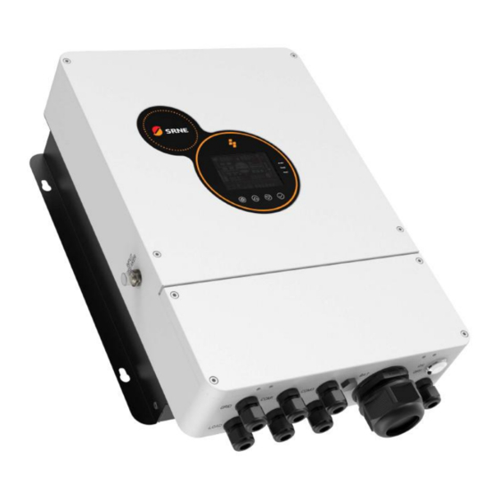
1.3 Appearance ⑨ ① Indicator light AC input ② ⑩ LCD screen RS485-2 Communication Port ③ ⑪ Touch button USB communication port RS485-1 Communication Port ④ ⑫ PV terminal (WIFI / GPRS) ⑤ ⑬ Battery terminal Dry-contact port ⑥ ⑭ Parallel communication A port Overload protector ⑦... -
Page 7: Dimension Drawing
1.4 Dimension drawing Solar hybrid inverter V1.1... -
Page 8: Installation Instructions
2. Installation instructions 2.1 Installation precautions Please read this manual carefully prior to installation to familiarize yourself with the installation steps. Be very careful when installing the battery. Wear safety goggles when installing a lead-acid liquid battery. Once coming into contact with the battery acid, rinse with clean water timely. Do not place metal objects near the battery to prevent short-circuit of the battery. -
Page 9: Wiring Specifications And Circuit Breaker Selection
2.2 Wiring specifications and circuit breaker selection Wiring and installation must comply with national and local electrical codes. Recommended PV array wiring specifications and circuit breaker selection: Since the output current of the PV array is affected by the type, connection method and illumination angle of the PV module, the minimum wire diameter of the PV array is calculated according to its short-circuit current;... - Page 10 Recommended battery input wire diameter and switch selection Recommended Rated battery Maximum Recommended Models battery wiring discharge charge circuit breaker type diameter current current HESP4840S100-H 100A 100A 2P—160A 30mm /2AWG HESP4846S100-H 118A 100A 2P—160A 30mm /2AWG HESP4850S100-H 125A 100A 2P—200A 30mm /2AWG...
-
Page 11: Installation And Wiring
2.3 Installation and wiring Installation steps: Step 1: Determine the installation position and the space for heat dissipation. Determine the installation position of the solar hybrid inverter, such as wall surface; when installing the solar hybrid inverter, ensure that there is enough air flowing through the heat sink, and space of at least 200mm to the left and right air outlets and 500mm to the above and below air outlets of the inverter shall be left to ensure natural convection heat dissipation. - Page 12 Step 2: Open 4 holes in the wall according to the following dimensions, and knock in expansion screws, as shown in the following figure: Step 3: Hang up the machine and tighten the screws. Solar hybrid inverter V1.1...
- Page 13 Step 4: Remove the terminal cover Step5: Connect the Wire. ( Note: The wire shall penetrate into the corresponding joint before crimping the terminal ) Solar hybrid inverter V1.1...
- Page 14 Connection method of AC I/O: Prior to AC I/O wiring, disconnect the external circuit breaker and confirm whether the cable used is thick enough. Please refer to Chapter "2.2 Wiring Specification and Circuit Breaker Selection"; According to the cable sequence and terminal position shown in the following figure, connect the AC input line properly, please connect the grounding wire first, then connect the live wire and the neutral wire;...
- Page 15 Ground Wire of the Entire Machine: As shown in the following figure, it is located on the bottom of the chassis and shall be be connected by O-terminal. It is recommended to use O-terminal with inner diameter of 6mm. Note: As far as possible, the ground cable should be much thicker as possible (the sectional area of wire should not be less than 4mm ) and the grounding point should be kept close to the inverter as possible.
- Page 16 wiring; the circuit breaker must be installed at the battery end. Please refer to Chapter 2.2 “Wiring Specification and Circuit Breaker Selection” for their selection. Before wiring, please be sure to disconnect the circuit breaker to prevent strong electric spark in the process of wiring and avoid short-circuiting the battery in the process of wiring.
-
Page 17: Parallel Machine Wire Connection
2.4 Parallel machine wire connection 2.4.1 Introduction Up to six units connected in parallel. When using the parallel operation function, the following connecting lines (package accessories) shall be firmly and reliably connected: Parallel communication line*1: 2.4.2 Precautions for connecting the parallel connecting lines Warning: PV connection: When connected in parallel, the PV arrays of each machine must be independent and the PV... - Page 18 connection precautions are the same as parallel connection in single phase. For specific wiring, please refer to 2.4.4 Wiring Diagram. AC IN wiring: Parallel connection in single phase: ensure L-to-L, N-to-N and PE-to-PE connection for all solar hybrid inverters, and that the connection is correct with the same wiring length and line diameter before power on, so as to avoid the abnormal operation of parallel system output caused by wrong connection.
-
Page 19: Schematic Diagram Of Parallel Connection In Single Phase
2.4.3 Schematic diagram of parallel connection in single phase The parallel communication line and current sharing detection line of the solar hybrid inverter need to be locked with screws after connecting. The schematic diagram is as follows: In case of parallel operation with multiple inverters, the schematic diagram of parallel connection is as follows: a)... - Page 20 b) Three solar hybrid inverters of the system connected in parallel: c) Four solar hybrid inverters of the system connected in parallel: Solar hybrid inverter V1.1...
- Page 21 d) Five solar hybrid inverters of the system connected in parallel: e) Six solar hybrid inverters of the system connected in parallel: Solar hybrid inverter V1.1...
-
Page 22: Schematic Diagram Of Parallel Connection In Three Phase
2.4.4 Schematic diagram of parallel connection in three phase The parallel communication line and current sharing detection line of the solar hybrid inverter need to be locked with screws after connecting. The schematic diagram is as follows: In case of parallel operation with multiple inverters, the schematic diagram of parallel connection is as follows: Parallel Operation in three phase : a)... - Page 23 b) Four solar hybrid inverters of the system connected in three phase: 2+1+1 system: c) Five solar hybrid inverters of the system connected in three phase: 3+1+1 system: Solar hybrid inverter V1.1...
- Page 24 2+2+1 system: d) Six solar hybrid inverters of the system connected in three phase: 2+2+2 system: Solar hybrid inverter V1.1...
- Page 25 3+2+1 system: 4+1+1 system: Solar hybrid inverter V1.1...
- Page 26 Note: Before starting up and running, please check whether the connection was correct to avoid any abnormalities in the system. All wiring must be fixed and reliable to avoid wire drop during use. When the AC output is wired to the load, it shall be properly wired according to the requirements of the electrical load equipment to avoid damage to the load equipment.
-
Page 27: Operating Modes
3. Operating modes 3.1 Charging mode 1、Solar First: priority shall be given to charging by PV, and mains charging will be started only when the PV has failed. It can fully utilize solar energy to generate power in the daytime and then switch to mains charging to keep the battery level, which can be used in regions where the grid is relatively stable and the feed-in tariff is relatively expensive. -
Page 28: Output Mode
3.2 Output mode 1、Solar First: PV and battery will power the load, with diversified charging modes available and output mode optional, when the Solar First Mode is selected, the use of green solar energy can be maximized for energy efficiency and emission reduction. Switch to Mains Power when PV has failed. This mode can maximize the use of solar energy while maintaining the battery power, which is suitable for regions with relatively stable power grid. -
Page 29: Lcd Screen Operating Instructions
4. LCD screen operating instructions 4.1 Operation and display panel The operation and display panel is shown below, including one LCD screen, 3 indicator lights and 4 operation buttons. 4.2 Operation buttons introduction Function Key Description Menu of Enter/Exit Settings Page Number/Option Increase Page Number/Option Decrease Under the menu of Settings, OK/Enter Options... -
Page 30: Lcd Screen Introduction
4.4 LCD screen introduction Icon function Icon function Indicates mains power Indicates the inverter is working Indicates generator Indicates home appliances Indicates solar power Indicates AC output is overload Solar hybrid inverter V1.1... - Page 31 Battery remaining capacity Load percentage is below 5% is below 5% Battery remaining capacity Load percentage is 5%~19% is 5%~19% Battery remaining capacity Load percentage is 20%~39% is 20%~39% Battery remaining capacity Load percentage is 40%~59% is 40%~59% Load percentage is 60%~79% Battery remaining capacity is 60%~79% Load percentage is 80%~100%...
- Page 32 Indicates that the machine is Indicates that the machine is currently in an alarm or fault currently in the parameter setting state state Indicates that the PV is in a Indicates that the PV is in a state direct load state of charge Indicates that the AC is in a Indicate that the Mains Power is in...
-
Page 33: Setup Parameters Description
Key Operation Instructions: Enter the setting menu and exit the set ting menu, please press After entering the setting menu, the parameter number [00] will flash. At this time, you can press the srne and key to select the parameter code to be set. Then press... - Page 34 Solar First Mode: switch to Mains Power when PV [01] PV 1ST has failed or battery is lower than Parameter [04] Set Value. Bypass self-adaptation; when the mains is [02] 50.0 Default connected, it automatically adapts to the mains frequency; when the mains is disconnected, the Output frequency output frequency can be set through this menu.
- Page 35 [06] ONLYPV Only PV charging, no mains charging is enabled. Maximum [07] 60A Default Set Range of 0~100A. charging current [08] USER User-defined, all battery parameters can be set. Sealed lead-acid battery with constant charge [08] SLd voltage of 57.6V and floating charge voltage of 55.2V.
- Page 36 Over-discharge Delay Time: when the battery voltage is lower than the Parameter [12], the Over discharge [13] 5S Default inverter output is turned off upon delay of time set delay time by this Parameter, with the Set Range of 5S~50S, Step of 5S.
- Page 37 sealed lead-acid battery and user-defined [21] ENA Start equalization charging immediately Equalization charging start-stop [21] DIS Default Stop equalization charging immediately [22] DIS Default NO ECO mode When the ECO mode is enabled, if the load is below 50W, the inverter output is delayed for 5 ECO mode minutes and then the output is turned off.
- Page 38 input source has change. Automatic switch to Mains Power is disabled [27] DIS Inverter overload to when the Inverter is overloaded. bypass Automatic switch to Mains Power when the [27] ENA Default inverter is overloaded. Current of charging [28] 60A Default AC output 230Vac, with the Set Range of 0~60A under grid electricity RS485 address...
- Page 39 PAC=PACE,RDA=RITAR,AOG=ALLGRAND BATTERY,OLT=OLITER,HWD=SUNWODA, [33] WOW Default DAQ=DAKING, WOW=SRNE, PYL=PYLONTECH, UOL=WEILAN [34] DIS Default Disable this Function When not connected to a battery or when the battery charging current is saturated, the surplus [34] TOGRID PV grid-connected PV energy is fed directly to the local load and to power generation the grid when bypassed.
- Page 40 charging time Default 2-section start [42] 00:00:00 Set Range: 00: 00-23: 59: 00. charging time Default 2-section end [43] 00:00:00 Set Range: 00: 00-23: 59: 00. charging time Default 3-section start [44] 00:00:00 Set Range: 00: 00-23: 59: 00. charging time Default 3-section end [45] 00:00:00...
- Page 41 [53] DIS Default Disable this Function. After the sectioned discharge function is enabled, Sectional discharge the power supply mode will change to AC 1ST function [53] ENA and the system will switch to battery inverter power supply only during the set discharge period or when the mains power is off.
- Page 42 Used to enter the user password to unlock the screen settings menu, factory default password Password input [64] 000000 "000000". Password input range "000000" ~ "065535". Used to set the user's password, the setting is User password visible after entering the password for 64 items, [65] 000000 setting the password setting range is "000000"...
-
Page 43: Battery Type Parameters
4.6 Battery type parameters For Lead-acid Battery : Battery type Sealed lead Colloidal lead Vented lead User-defined acid battery acid battery acid battery (User) Parameters (SLD) (GEL) (FLD) Overvoltage disconnection 36~60V voltage (Adjustable) Battery fully charged recovery point (Adjustable) (Adjustable) (Adjustable) (Adjustable) 36~60V... - Page 44 For Lithium Battery : Battery type (NCM13) (NCM14) (LFP16) (LFP15) (LFP14) Parameters Overvoltage disconnection voltage 50.4V 54.8V 53.6V 50.4V 47.6V Battery fully charged recovery point( item 37 ) (Adjustable) (Adjustable) (Adjustable) (Adjustable) (Adjustable) 53.2V 57.6V 56.8V 53.2V 49.2V Equalizing charge voltage (Adjustable) (Adjustable) (Adjustable)
-
Page 45: Other Functions
5. Other functions 5.1 Dry contact Working principle: This dry contact can control the ON/OFF of the diesel generator to charge the battery. ① Normally, the terminals are that the NC-N point is closed and the NO-N point is open; ② When the battery voltage reaches the low voltage disconnection point, the relay coil is energized, and the terminals turn to that the NO-N point is closed while NC-N point is open. -
Page 46: Parallel Communication Function (Parallel)
5.5 Parallel communication function (parallel) This port is used for parallel communication, through which the parallel modules can communicate with each other. Each machine has two 8Pin ports, one for the parallel_A and one for the parallel_B. When connecting, make sure to connect the local Parallel_A to the parallelized machine Parallel_B, or the local Parallel_B should be connected to the parallelized machine Parallel_A. - Page 47 When the battery voltage reaches the low voltage disconnection Battery low voltage point, the battery discharging will be automatically stopped to prevent protection the battery from being over-discharged and damaged. When a short-circuit fault occurs at the load output for more than Load output short 200ms, the output AC voltage is immediately switched off and then circuit protection...
-
Page 48: Fault Code
Parallel battery In parallel operation, the equipment will be protected when the voltage difference battery connection is inconsistent and the battery voltage is greatly protection different from that detected by the host. Parallel AC voltage In parallel operation, the equipment will be protected when the AC IN difference input connection is inconsistent. - Page 49 BusOverVoltSw Bus overvoltage (software protection) 【08】 PvVoltHigh PV overvoltage protection 【09】 PvOCSw Boost overcurrent (software protection) 【10】 PvOCHw Boost overcurrent (hardware protection) 【11】 OverloadBypass Bypass overload protection 【13】 OverloadInverter Inverter overload protection 【14】 AcOverCurrHw Inverter overcurrent (hardware protection) 【15】 InvShort Inverter short circuit protection 【17】...
- Page 50 ModelNumErr Model setting error 【23】 Inverted AC Output Backfills to Bypass AC RlyShort 【26】 Input BusVoltLow Internal battery boost circuit failure 【29】 Alarm given when battery capacity rate is BatCapacityLow1 lower than 10% (setting BMS to enable 【30】 validity) Alarm given when battery capacity rate is BatCapacityLow2 lower than 5% (setting BMS to enable 【31】...
- Page 51 Inconsistent system firmware version in SysFwVersionDiff 【42】 parallel mode ParaLineContErr Parallel line connection error in parallel mode 【43】 Serial number error No serial number set at factory 【44】 Error setting of split- Item [31] setting error 【45】 phase mode Low insulation PV1+, PV2+ and PV- abnormally low 【56】...
-
Page 52: Handling Measures For Part Of Faults
6.3 Handling measures for part of faults Fault Faults Remedy code Check if the battery switch or PV switch is closed; Display No display on the screen whether the switch is in the "ON" state; press any button on the screen to exit the screen sleep mode. Check that the battery voltage does not exceed the Battery overvoltage protection value. - Page 53 Inconsistent system Check whether the software version of each inverter is 【42】 firmware version in parallel consistent. mode 【44】 Serial number error Incorrect device serial number setting. There is a device in the parallel system with the wrong 【45】 Parallel mode error parallel mode setting.
-
Page 54: Troubleshooting
7.Troubleshooting In order to maintain the best long-term performance, it is recommended to conduct following checks twice a year. Make sure that the airflow around the unit is not blocked and remove any dirt or debris from the heat sink. Check that all exposed wires are damaged by exposure to sunlight, friction with other objects around them, dryness, bite by insects or rodents, etc., and the wires shall be repaired or replaced if necessary. -
Page 55: Technical Parameters
8. Technical parameters HESP4850S100-H Model HESP4840S100-H HESP4846S100-H HESP4860S100-H HESP4855S100-H Battery input Rated battery input 48V ( minimum start-up voltage 44V ) voltage Battery voltage 40-60Vdc ± 0.6Vdc (undervoltage alarm / shutdown voltage / overvoltage range alarm / overvoltage recovery etc.) Battery type Lead-acid / Li-ion / User Defined Off-grid output... - Page 56 Power Factor 0.8 leading to 0.8 lagging Rated voltage 230Vac (Vac) Frequency 50Hz/60Hz Mains charging Max. charging current Charging current ± 5Adc error Charging voltage 40–58Vdc range Short-circuit Circuit breakers and blown fuses protection Circuit Breaker Specifications Max. efficiency of mains charging Overcharge Charge off after warning...
- Page 57 Num. of parallel 1-6 units units Certification specification Specification CE(IEC 62109-1/2)、CEI0-21、 VDE-AR-N-4105、EN50549-1 approval EN61000、FCC-SODC Operating -25°C to 60°C(>45℃ derate) temperature range Storage -25°C ~ 60°C (-13°F ~ 140°F) temperature range Humidity range 0% to 100% Noise ≤60dB Protection level IP65 Heat Dissipation Forced air cooling, adjustable air speed Communication...
Need help?
Do you have a question about the HESP Series and is the answer not in the manual?
Questions and answers