
Related Manuals for Srne HES4855S100-H


Summary of Contents for Srne HES4855S100-H
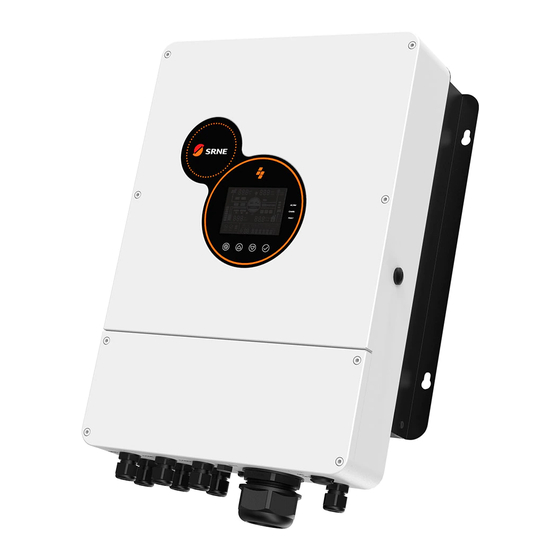
- Page 1 Solar Hybrid Inverter User Manual Product Models HES4855S100-H Solar Hybrid Inverter V1.0...
- Page 2 Important Safety Instructions Please keep this Manual for future reference This Manual contains all the safety, installation and operation instructions of HES series PV energy-storage hybrid inverter. Please read all instructions and precautions in this Manual carefully before installation and use. The inverters have internal unsafe voltage, in order to avoid personal injury, users should not disassemble ...
-
Page 3: Table Of Contents
CONTENTS 1. General information ......................... 4 1.1 Product overview and features ..............................4 1.2 Introduction to the Basic System ..............................5 1.3 Product Features ....................................6 1.4 Dimensional Diagram ..................................7 2. Installation Instructions ........................8 2.1 Precautions for Installation ................................8 2.2 Wiring Specification and Circuit Breaker Selection ......................8 2.3 Installation and Wiring................................ -
Page 4: General Information
1. General information 1.1 Product overview and features HES series is a new type of solar hybrid inverter, integrating solar energy storage and mains charging and AC sine-wave output. It is controlled by DSP and has the features of high response speed, high reliability and high industrial standard through state-of-art control algorithm. -
Page 5: Introduction To The Basic System
1.2 Introduction to the Basic System The following figure shows the system application scenario of this Product. A complete system shall include the following parts: PV Module: convert light energy into direct current energy, charge the battery through inverter, or directly invert into AC to supply power to the load. -
Page 6: Product Features
1.3 Product Features ⑧ Indicator light RS485-2 Communication Port ② ⑨ LCD screen USB communication port ③ ⑩ Touch button RS485-1 Communication Port ⑪ ④ PV terminal Dry-contact port ⑫ ⑤ Battery terminal Overload protector ⑬ ⑥ AC output CAN communication port ⑦... -
Page 7: Dimensional Diagram
1.4 Dimensional Diagram Location of Mounting Holes Solar Hybrid Inverter V1.0... -
Page 8: Installation Instructions
2. Installation Instructions 2.1 Precautions for Installation Please read this Manual carefully to familiarize yourself with the installation steps before installing. Take great care when installing the battery. Wear protective goggles when installing the lead-acid liquid battery. Once contacting the acid solution of battery, please rinse with clear water in time. Avoid placing any metal object near the battery against short-circuiting. - Page 9 Recommended circuit Models diameter current breaker model HES4855S100-H 2P—25A /10AWG Note: The input voltage of PV panels in series shall not exceed the maximum open-circuit voltage corresponding to the Model. Refer to the following table for recommended AC input wire diameter and switch ...
-
Page 10: Installation And Wiring
2.3 Installation and Wiring Installation Steps: Step 1: Determine the installation position of the Inverter. If installing the inverter on wall, please make sure that there is enough air flowing through the heat sink of the Inverter, leaving 200mm operating space on the left and right of the Inverter and 500mm air inlet and outlet heat dissipation space on the top and bottom. - Page 11 Step 2: Open 4 holes in the wall according to the following dimensions, and knock in expansion screws, as shown in the following figure: Step 3: Hang up the machine and tighten the screws. Solar Hybrid Inverter V1.0...
- Page 12 Step 4: Remove the terminal protection cover. Step 5: Connect the Wire. (Note: The wire shall penetrate into the corresponding joint before crimping the terminal.) Connection method of AC I/O: ① Prior to AC I/O wiring, disconnect the external circuit breaker and confirm whether the cable used is thick enough.
- Page 13 L: Live Wire N: Neutral Wire : Ground Wire ③ Connect the AC output line properly according to the cable sequence and terminal position shown in the above figure. Please connect the ground wire first, then the live wire and the neutral wire. Wiring Method of PV Input: ①...
- Page 14 Ground Wire of the Entire Machine: As shown in the following figure, it is located on the bottom of the chassis and shall be be connected by O- terminal. It is recommended to use O-terminal with inner diameter of 6MM. Note: As far as possible, the ground cable should be much thicker as possible (the sectional area of wire should not be less than 4mm ), and the grounding point should be kept close to the Inverter as possible.
- Page 15 installed at the battery end. Please refer to Chapter 2.2 “Wiring Specification and Circuit Breaker Selection” for their selection; prior to wiring, please be sure to disconnect the circuit breaker to prevent strong electric spark in the process of wiring and avoid short-circuiting the battery in the process of wiring; if the inverter is applied in any area with frequent lightning, it is recommended to install an external surge protection device at PV input.
-
Page 16: Working Mode
3. Working mode 3.1 Charging Mode 1. Solar First: priority shall be given to charging by PV, and mains charging will be started only when the PV has failed. It can fully utilize solar energy to generate power in the daytime and then switch to mains charging to keep the battery level, and can be used in regions where the grid is relatively stable and the feed-in tariff is relatively expensive. -
Page 17: Output Mode
3.2 Output Mode 1. Solar First: PV and battery will power the load, with diversified charging modes available and output mode optional, when the Solar First Mode is selected, the use of green solar energy can be maximized for energy efficiency and emission reduction. -
Page 18: Lcd Screen Operating Instructions
4. LCD Screen Operating Instructions 4.1 Operation and Display Panel The operation and display panel is shown below, including one LCD screen, 3 indicator lights and 4 operation buttons. 4.2 Introduction to Operation Keys Function Key Description Menu of Enter/Exit Settings Page Number/Option Increase Page Number/Option Decrease Under the menu of Settings, OK/Enter Options... -
Page 19: Introduction To Lcd Screen
4.4 Introduction to LCD Screen PAGE VAHz PV LOAD PV CHG AC CHG UNDER END OF MASTER BYPASS VOLT DISCHG BATT MAIN SOLAR FULL BMS FAULT FIRST FIRST FIRST USER OVER LOAD 100% kWh% VAHz FAULT SETUP SETUP DATE START MAINS CHARGE VOLT... - Page 20 Indicates that the current battery type Indicates that the battery is fully charged of the machine is user-defined Indicates that the current battery type Indicates that the current battery type of of the machine is flooded lead-acid the machine is sealed lead-acid battery battery Indicates that the current battery type of Indicates that the current battery type...
- Page 21 Real-time data viewing method On the LCD main screen, press the button for page turning to view the real-time data of the machine. Battery side Mains side Load side Comprehensive Page PV side parameters parameters parameters parameters parameters PV Voltage Battery Voltage AC Voltage Load Voltage...
-
Page 22: Description Of Setting Parameters
4.5 Description of Setting Parameters Key Operation Instructions: Enter the setting menu and exit the set ting menu, please press , After entering the setting menu, the parameter number [00] will flash. At this time, you can press the key to select the parameter code to be set. - Page 23 bypass output is loaded, and only PV charging can be activated when the inverter is working. The Mains Power is charged first, and PV charging is [06] AC1ST started only when the Mains Power has failed Priority shall be given to charging by PV and mains [06] PV1ST charging will be initiated only when the PV has failed.
- Page 24 Battery under-voltage alarm point: when the battery voltage is lower than such criterion, under-voltage Battery under voltage alarm will be given, the output will not be shut down, [14] 44V Default alarm point with the Set Range of 40V~52V, Step of 0.4V, available when battery type is user-defined and lithium battery.
- Page 25 Over-temperature automatic restart is disabled. If over- [24] DIS temperature occurs, the output will be shut down, and the machine will not be restarted for output. Auto restart upon Enable automatic restart upon over-temperature. If over- over-temperature [24] ENA Default temperature occurs, shut down output, and restart output after the temperature has dropped.
- Page 26 2-section end [43] 00:00:00 Default Set Range: 00: 00-23: 59: 00 charging time 3-section start [44] 00:00:00 Default Set Range: 00: 00-23: 59: 00 charging time 3-section end [45] 00:00:00 Default Set Range: 00: 00-23: 59: 00 charging time [46] DIS Default Disable this Function After the sectioned charging function is enabled, the power supply mode will change to BT1ST, and system will...
-
Page 27: Battery Type Parameter List
4.6 Battery Type Parameter List Lead acid battery: Battery type Sealed lead acid Gel lead acid Flooded lead acid User-defined (FLD) (SLD) (GEL) (User) Parameter Overvoltage break voltage 40~60V Equalization Voltage 56.8V (adjustable) 40~60V Boost Voltage 57.6V 56.8V 57.6V (adjustable) 40~60V Float charge voltage 55.2V... - Page 28 Lithium battery: Battery Type User-defined (NCM13) (NCM14) (LFP16) (LFP15) (LFP14) (User) Parameters Overvoltage break voltage 40~60V Equalization Voltage (adjustable) 53.2V 57.6V 56.8V 53.2V 49.2V 40~60V Boost Voltage adjustable adjustable adjustable adjustable adjustable (adjustable) 53.2V 57.6V 56.8V 53.2V 49.2V 40~60V Float charge voltage adjustable adjustable adjustable...
-
Page 29: Other Functions
5. Other Functions 5.1 Dry contact Function Working Principle: This dry contact can control the switch of diesel generator to charge the battery. (1) Under normal circumstances, this terminal is closed at NC-N point and opened at NO-N point; ② when the battery voltage reaches the low-voltage breaking point, the coil of the relay is electrified, and the NO-N point is closed and the NC-N point is opened, at this time, the NO-N point can drive resistive load 125VAC/1A, 230VAC/1A and 30VDC/1A. -
Page 30: Protection
6. Protection 6.1 Protection Functions Available Protection function Description When the charging current of the configured PV array exceeds the PV rated Current limiting protection current, charging will be at the rated current. Protection against reverse In the nighttime, since the voltage of battery is greater than that of the PV charging in the nighttime module, the battery is prevented from discharging through the PV module. -
Page 31: Meaning Of Fault Code
6.2 Meaning of Fault Code Whether the output Fault Code Fault Description is affected 【01】 BatVoltLow Battery under-voltage alarm Software protection of battery discharge 【02】 BatOverCurrSw average overcurrent 【03】 BatOpen Battery Disconnected Alarm 【04】 BatLowEod Battery undervoltage stop discharge alarm 【05】... -
Page 32: Partial Troubleshooting Measures
6.3 Partial Troubleshooting Measures Fault code Faults Handling measures Check if the battery circuit breaker or the PV circuit breaker has been closed; if the switch is in the "ON" No display on the screen Display state; press any button on the screen to exit the screen sleep mode. -
Page 33: System Maintenance
7. System Maintenance In order to maintain the best long-term working performance, it is recommended to check the followings twice a year. 1. Make sure that the airflow around the inverter is not blocked, and remove any dirt or debris from the heat sink. 2. -
Page 34: Technical Parameters
8. Technical Parameters Type HES4855S100-H Mains Power mode Rated input voltage 220/230Vac (170Vac~280Vac)±2% Input voltage range (90Vac~280Vac)±2% Frequency 50Hz/60Hz (auto detection) 47±0.3Hz~55±0.3Hz(50Hz); Frequency range 57±0.3Hz~65±0.3Hz(60Hz); Overload/short-circuit Circuit breaker protection Efficiency >95% Conversion time 10ms (typical) (Bypass and Inversion) AC backfeed protection... - Page 35 40Vdc-60Vdc ± 0.6 Vdc (under--voltage alarm/shutdown voltage/over-voltage Battery voltage range alarm/over-voltage recovery … LCD screen can be set) Power saving mode Non-ECO mode ≤100W; ECO mode ≤50W Charging under Grid Electricity Battery type Lead-acid or lithium battery Maximum Charging Current Charging current error ±5Adc Charging voltage range...
Need help?
Do you have a question about the HES4855S100-H and is the answer not in the manual?
Questions and answers