
Subscribe to Our Youtube Channel
Related Manuals for BED BATH & Beyond I870000772A1


Summary of Contents for BED BATH & Beyond I870000772A1
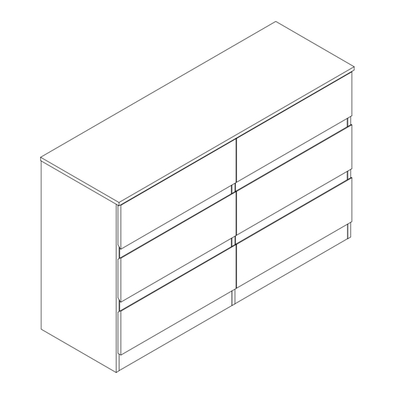
- Page 1 Bucket cabinet I870000772A1 / I870000772A2 Assembly Instructions Dimensions Width - 120CM Depth - 40CM Height - 76CM Important – Please read these instructions fully before starting assembly B034# Issue 2 - 08/13/23...
- Page 2 Safety and Care Advice Important – Please read these instructions fully before starting assembly • Check you have all the • During assembly do not stand • To reduce components and tools listed on or put weight on the product, the likelihood of the following pages.
- Page 3 Components - Panels Please check you have all the panels listed below 1 PC 1 PC 1 PC 2 PCS 2 PCS 1 PC 1 PC 1 PC 1 PC 1 PC 6 PCS 6 PCS 6 PCS 6 PCS 2 PCS 2 PCS 2 PCS...
- Page 4 Components - Fittings Please check you have all the panels listed below Note: The quantities below are the correct amount to complete the assembly. In some cases more fittings may be supplied than are required. Male Camlock x 54 Female Camlock x 54 Dowel x 6 Protective Feet x 10 6.8*48mm Screw x 4...
- Page 5 Using Camlocks Step 1 Step 2 DO NOT OVER TIGHTEN. Connect the male Push the male camlock NE PAS SERRER EXCESSIVEMENT. camlock as diected in into the entry hole. the assembly instructions using a scewdriver . Step 4 Step 3 Insert the female Turn the female camlock camlock as shown in the...
- Page 6 Assembly Instructions...
- Page 7 Assembly Instructions Step 1 Ball Bearing Slide Slider runner Ball Bearing Slide G x 6 Slider runner FRONT Step 2 Attention: 1. Please locate the holes from the back of part G1. G1 Back: P x 12 FRONT Attention: 1. Please locate the holes from the back of part G1. G1 Back:...
- Page 8 Assembly Instructions Step 3 A x 16 Step 4 ° P x 12 FRONT Attention: 1. Please locate the holes from the back of part G1. FRONT G1 Back: Attention: 1. Please locate the holes from the back of part G1. G1 Back:...
- Page 9 Assembly Instructions Step 5 A x 8 Step 6 B x 8...
- Page 10 Assembly Instructions Step 7 B x 4 Step 8 B x 4...
- Page 11 Assembly Instructions Step 9 D x 4 Step 10 N x 1...
- Page 12 Assembly Instructions Step 11 N x 1 Step 12...
- Page 13 Assembly Instructions Step 13 B x 8 Step 14 E x 10...
- Page 14 Assembly Instructions Step 15 N x 1 Step 16 O x 4...
- Page 15 Assembly Instructions Step 17 C x 6 Step 18 A x 6...
- Page 16 Assembly Instructions Step 19 B x 6 Step 20 A x 24...
- Page 17 Assembly Instructions Step 21 L x 24 Step 22 B x 8...
- Page 18 Assembly Instructions Step 23 B x 8 Step 24 B x 8...
- Page 19 Assembly Instructions Step 25 Step 26 F x 24...
- Page 20 Assembly Instructions Step 27 M x 12 Step 28 I x 24 Attention: 1.Align the slide runners on the drawer with the unit and push it carefully inside until it stops. If the drawer does not go in smoothly please take it out and repeat the step.
- Page 21 Assembly Instructions Step 29 I x 12 Step 30 J x 8 K x 8...
- Page 22 Assembly Instructions Step 31 The unit is floor standing, but it is H x 2 recommended that the unit is secured to the wall. 1. Move the unit into desired position. 2. Mark the wall with a suitable scribe the position of the fixing holes.
- Page 23 Assembly Instructions Step 32 Effective distance of light control: within 3 meters Assembly is complete.
Need help?
Do you have a question about the I870000772A1 and is the answer not in the manual?
Questions and answers