Advertisement
Quick Links
I N S TA L L AT I O N , O P E R AT I O N A N D
M A I N T E N A N C E
I N S T R U C T I O N S
SmartVu™
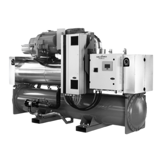
Water-Cooled Variable Speed Screw Chillers
Water-Sourced Variable-Speed Screw Heat Pumps
AquaForce
PUREtec greenspeed with
®
R-1234ze(E) or optionally with R-515B refrigerant
30XW-VZE / 30XWHVZE 451A-1601A
Nominal cooling capacity: 448-1635 kW - 50Hz
Nominal heating capacity: 523-1926 kW
Original document
Advertisement

Subscribe to Our Youtube Channel
Related Manuals for Carrier 30XW-VZE


Summary of Contents for Carrier 30XW-VZE
- Page 1 SmartVu™ Water-Cooled Variable Speed Screw Chillers Water-Sourced Variable-Speed Screw Heat Pumps AquaForce PUREtec greenspeed with ® R-1234ze(E) or optionally with R-515B refrigerant 30XW-VZE / 30XWHVZE 451A-1601A Nominal cooling capacity: 448-1635 kW - 50Hz Nominal heating capacity: 523-1926 kW Original document...
- Page 2 5.7 - 24 and 230 V power reserve for the user ..........................21 6 - APPLICATION DATA ................................... 22 6.1 - 30XW-VZE /30XWHVZE Operating limits ..........................22 6.2 - Minimum chilled water flow ..............................23 6.3 - Maximum chilled water flow ..............................23 6.4 - Condenser water flow rate ..............................
- Page 3 11.8 - Frequency variator maintenance ............................36 11.9 - High pressure safety loop periodic test ..........................36 12 - START-UP CHECKLIST FOR 30XW-VZE LIQUID CHILLERS (USE FOR JOB FILE) ............37 13 - SYSTEM FINAL SHUTDOWN ..............................39 13.1 - Shutting down..................................39 13.2 - Recommendations for disassembly ............................
- Page 4 1 - INTRODUCTION Units Application Range Flammable refrigerant regulations & standards The 30XW-VZE / 30XWHVZE units are designed to cool or heat Local building codes and safety standards shall be followed. water (or brine) for the air conditioning of buildings and industrial...
- Page 5 Failure to do so may result in damage to the equipment protective devices fitted to these machines are classified as and physical injury. follows: Carrier strongly recommends employing a specialised company to unload the machine. Safety Over pressure protection in It is compulsory to wear personal protection equipment.
- Page 6 An example of test procedure without removing the pressure Option 194 : Dual relief valve on a changeover valve switch is given in Section 11.9 of this manual. Consult Carrier Service for this type of test. If the relief valves are installed on a change-over manifold, CAUTION: If the test leads to replacing the pressure switch, this is equipped with a relief valve on each of the two outlets.
- Page 7 1 - INTRODUCTION Refrigerant Circuit interventions Personal Protective Equipment (PPE) When performing service on the refrigeration circuit, ventilate Equip the engineers that work on the unit as follows: the area prior to performing any work and check for presence Operations of refrigerant.
- Page 8 AT T E N T I O N : T h e f r e q u e n c y v a r i a t o r s u s e d i n t h e shows this frequency, as originally published in the regulation. 30XW-VZE/30XWHVZE units are equipped with capacitor Check whether an inspection frequency is also set by other batteries with a discharge time of twenty (20) minutes after regulations or standards applicable to your system (e.g.
- Page 9 1 - INTRODUCTION 1.4 - Repair safety considerations Do not use your hands to check possible refrigerant leaks. Avoid contact with liquid refrigerant and/or Oil on the skin or Equip the engineers that work on the unit with the protections splashing it into the eyes.
- Page 10 1 - INTRODUCTION Refrigerant Charge filling Ensure that you are using the correct refrigerant type before recharging the unit with the total quantity of refrigerant (either R-1234ze(E) or R-515B) as indicated on the unit name plate. Charging any refrigerant other than the original charge type stated on the nameplate will impair machine operation and can even lead to a destruction of the compressors.
- Page 11 2 - PRELIMINARY CHECKS 2.1 - Check equipment received 2.2.3 - Checks before system start-up Before the start-up of the refrigeration system, the complete ■ Inspect the unit for damage or missing parts. If damage is installation, including the refrigeration system must be verified detected, or if shipment is incomplete, immediately file a claim against the installation drawings, dimensional drawings, system with the shipping company.
- Page 12 3 - DIMENSIONS, CLEARANCES 3.1 - 30XW-VZE/30XWHVZE 451A-651A refer to the dimensional drawings. See detail J See detail K See detail H Dimensions en mm 30XW-VZE/30XWHVZE 451A 1743 1087 3059 1086 168,3 168,3 2800 501A 1743 1087 3059 1086 168,3 168,3 2800...
- Page 13 3 - DIMENSIONS, CLEARANCES 3.2 - 30XW-VZE/30XWHVZE 851A-1301A See detail A See detail C See detail B Dimensions en mm 30XW-VZE/30XWHVZE 851A 1998 1514 1164 4730 1162 219,1 219,1 4500 1001A 1998 1514 1164 4730 1162 219,1 219,1 4500 1101A 2051 1514 1164 4730 1264 219,1 219,1 4500...
- Page 14 3 - DIMENSIONS, CLEARANCES 3.3 - 30XW-VZE/30XWHVZE 1401A-1601A See detail J See detail H See detail K Dimensions in mm 30XW-VZE/30XWHVZE 1401A 2425 1444 1461 4904 1474 219 219 4600 650 1300 1601A 2425 1638,5 1461 5293 1474 219 219 5000 650 1300...
- Page 15 4 - PHYSICAL AND ELECTRICAL DATA 4.1 - Physical data 30XW-VZE/30XWHVZE 451A 501A 601A 651A 851A 1001A 1101A 1201A 1301A 1401A 1601A Sound levels - standard unit Sound power level dB(A) Sound pressure level at 1 m dB(A) Sound levels - standard unit + option 257...
- Page 16 4 - PHYSICAL AND ELECTRICAL DATA 4.2 - Electrical data 30XW-VZE /30XWHVZE 451A 501A 601A 651A 851A 1001A 1101A 1201A 1301A 1401A 1601A Power circuit Nominal power supply V-ph-Hz 400-3-50 Voltage range 360-440 Control circuit 24 V via the built-in transformer...
- Page 17 (4) Values for standard AND for option 150 The short circuit stability current values above are suitable for TN system (Earthing system type) 4.4 - Compressor usage 30XW-VZE/30XWHVZE 451A 501A 601A...
- Page 18 4 - PHYSICAL AND ELECTRICAL DATA Electrical Note 30XW-VZE / 30XWHVZE units Electrical data notes and operating conditions, 30XW-VZE / 30XWHVZE units 5. The unit is designed for connection to TN systems (IEC 60364). For IT systems the earth connection must not be at the network earth. Provide a local earth, •...
- Page 19 AB = 406 V; BC = 399 V; AC = 394 V which will invalidate the Carrier warranty. If the phase Average voltage = (406 + 399 + 394)/3 = 1199/3 = 399.7 say 400 V...
- Page 20 Wire sizing is the responsibility of the installer, and depends on the characteristics and regulations applicable to each installation site. The cable selections given in this document are therefore only given as a guide and do not in any way incur Carrier’s liability. After wire sizing has been completed, using the certified dimensional drawing, the installer must ensure easy connection and define any modifications necessary on site.
- Page 21 5 - ELECTRICAL CONNECTION 5.5 - Power cable entry The power cables can enter the unit control box from above the unit. A removable aluminium plate on the upper part of the control box face allows introduction of the cables. Refer to the certified dimensional drawing for the unit.
- Page 22 6 - APPLICATION DATA 6.1 - 30XW-VZE /30XWHVZE Operating limits 6.1.1 - 30XW-VZE/30XWHVZE 451A-1301A operating 6.1.2 - 30XW-VZE/30XWHVZE 1401A-1601A limit operating limit 30XW-VZE/30XWHVZE 451A-1301A Minimum Maximum 30XW-VZE/30XWHVZE 1401A-1601A Minimum Maximum Evaporator Evaporator Entering temperature at start-up 35 °C Entering temperature at start-up °C...
- Page 23 6 - APPLICATION DATA 6.2 - Minimum chilled water flow 6.4 - Condenser water flow rate The minimum chilled water flow is shown in the table in chapter The minimum and maximum condenser water flow rates are shown 6.6. in the table in chapter 6.6 “Evaporator and condenser water flow rates”.
- Page 24 6 - APPLICATION DATA 6.5 - Standard and optional number of water passes 30XW-VZE/30XWHVZE 451A 501A 601A 651A 851A 1001A 1101A 1201A 1301A 1401A 1601A Evaporator Standard Option 100C Condenser Standard Option 102C 6.6 - Evaporator and condenser water flow rates These below values are given for standard units.
- Page 25 6 - APPLICATION DATA 6.9 - Evaporator pressure drop curves 6.10 - Condenser pressure drop curves Units with two evaporator passes (standard) Units with two condenser passes (standard) Water flow rate, l/s Water flow rate, l/s Units with one evaporator pass (option 100C) Units with one condenser pass (option 102C) 30 40 50 60 70...
- Page 26 - In case additives or other fluids than those recommended by Carrier are used, ensure that the fluids are not considered as a gas, and that they belong to class 2, as defined in directive 2014/68/CE.
- Page 27 In this case two additional and the chilled water pump interlock must be connected. sensors must be added on the common piping. Failure to follow this instruction will void the Carrier guarantee. All parameters, required for the Lead/Lag function must be configured using the MST_SLV menu.
- Page 28 8 - HEAT PUMPS 30XWHVZE 8.1 - Physical data for heat pumps The physical data for 30XWHVZE for heat pumps are the same as for the 30XW-VZE units. Please refer to chapter 4.1. 8.2 - Electrical data for heat pumps The electrical data for 30XWHVZE for heat pumps are the same as for the 30XW-VZE units.
- Page 29 The 06T and 06Y screw compressor is approved for use with the pressure given on the unit nameplate. following lubricant: CARRIER MATERIAL SPEC PP 47-38. - The reports of periodical checks by the user or operator must Contact Carrier ERCD to purchase oil top-up.
- Page 30 Carrier. Condenser and oil separator Compressor 06T or 06Y The 30XW-VZE/30XWHVZE chiller uses a heat exchanger that is a combination condenser and oil separator. It is mounted below the evaporator. Discharge gas leaves the compressor and flows HPS :...
- Page 31 10 - OPTIONS AND ACCESSORIES Use for Options N° Description Advantages 30XW-(H)VZE range Light-brine Implementation of new algorithms of control to allow Matches with most application requirements for 451A-1601A solution, down to chilled brine solution production down to -3 °C when ground-sourced heat pumps and fits with many (see dedicated -3 °C...
- Page 32 10 - OPTIONS AND ACCESSORIES Use for Options N° Description Advantages 30XW-(H)VZE range Valve replacement and inspection Dual relief valve Three-way valve upstream of dual relief valves on the facilitated without refrigerant loss. 451A-1601A on 3 way valve evaporator and the oil separator Comforms to European standard EN378/BGVD4 Additional tests on the water heat exchangers: supply...
- Page 33 A Carrier Service maintenance contract is the best way to ensure - Check the unit alarm report when the unit does not work (see the maximum operating life for your equipment and, through the report in the SmartVu™...
- Page 34 If open for longer, blanket the circuit with nitrogen. NOTE: Any deviation or non-observation of these maintenance criteria will render the guarantee conditions for the HVAC unit nul and void, and the manufacturer, Carrier France, will no longer be held responsible Legend...
- Page 35 11 - STANDARD MAINTENANCE 11.5 - Tightening torques for the main bolts and screws Torque value, Screw type Used for 451A-1301A 1401A-1601A N·m Structure M20 nut Chassis M20 nut Heat exchanger side-side connection M16 nut Compressor fixing H M16 screw Compressor sub assy frame H M16 screw Flat angle bracket for Heat exchanger...
- Page 36 The switch that has been selected for detecting reverse rotation Test> parameter [HP_TEST] to 0 for circuit A or 1 for the B circuit. is Carrier part number HK01CB001. This switch opens the contacts The corresponding circuit starts to perform the HP test.
- Page 37 12 - START-UP CHECKLIST FOR 30XW-VZE LIQUID CHILLERS (USE FOR JOB FILE) Preliminary information Job name: ........................................ Location: ........................................Installing contractor: ....................................Distributor: ....................................... Unit Model: ....................Compressors Circuit A Circuit B Model number.................. Model number ................Serial number .................. Serial number ................
- Page 38 WARNING: Operation of the chiller with an improper supply voltage or excessive phase imbalance constitutes abuse which will invalidate the Carrier warranty. If the phase imbalance exceeds 2% for voltage, or 10% for current, contact your local electricity supplier at once and ensure that the chiller is not switched on until corrective measures have been taken.
- Page 39 13 - SYSTEM FINAL SHUTDOWN The unit is fully or partially recyclable. After use, it may contain refrigerant vapors and oil residues. Some parts are painted. 13.1 - Shutting down Separate the units from their energy sources, allow them to cool then drain them completely. 13.2 - Recommendations for disassembly Read the information relating to the presence of potentially dangerous substances in the product and their precautions for use (REACH, Regulation no.
- Page 40 CARRIER participates in the ECP programme for LCP-HP Check ongoing validity of certificate: www.eurovent-certification.com The quality management system of this product’s assembly site has been certified in accordance with the requirements of the ISO 9001 standard (latest current version) after an assessment conducted by an authorized independent third party.
Need help?
Do you have a question about the 30XW-VZE and is the answer not in the manual?
Questions and answers