Advertisement
Quick Links
Advertisement

Subscribe to Our Youtube Channel
Related Manuals for Struers Secotom-15


Summary of Contents for Struers Secotom-15
- Page 1 Secotom-15 Manual No.: 15997002 Instruction Manual Revision A Date of Release 2018.01.10...
- Page 2 Secotom-15 Instruction Manual IMPORTANT READ the instruction manual carefully before use. Keep a copy of the manual in an easy-to-access place for future reference. For automatic cutting of metallic or other solid materials for further Intended use: material inspection and only to be operated by skilled/trained personnel.
- Page 3 Service Manuals: Struers Service Manuals may only be used by a trained technician authorised by Struers. The Service Manual may only be used in connection with Struers equipment covered by the Service Manual. Struers assumes no responsibility for errors in the manual text/illustrations. The information in this manual is subject to changes without notice.
- Page 4 Secotom-15 Instruction Manual...
- Page 5 The equipment should only be used for its intended purpose and as detailed in the Instruction Manual. The equipment is designed for use with consumables supplied by Struers. If subjected to misuse, improper installation, alteration, neglect, accident or improper repair, Struers will accept no responsibility for damage(s) to the user or the equipment.
- Page 6 Secotom-15 Instruction Manual...
- Page 7 Secotom-15 Instruction Manual Icons and typography The following icons and typographic conventions are used in this instruction manual: Icons and Safety Messages ELECTRICAL HAZARD indicates an electrical hazard which, if not avoided, will result in death or serious injury. DANGER indicates a hazard with a high level of risk which, if not avoided, will result in death or serious injury.
- Page 8 Secotom-15 Instruction Manual Colour Inside Logo The 'colour inside' logo on the cover page of this Instruction Manual indicates that it contains colours which are considered to be useful for the correct understanding of its contents. Users should therefore print this document using a colour printer.
- Page 9 Table of Contents Page 1. Getting Started Checking the Contents of the Packing Box ........11 Removing Secotom-15 from the Pallet ..........11 Placing Secotom-15 ................ 11 Getting Acquainted with Secotom-15 ..........12 Rear of Secotom-15 ................ 14 Supplying Power ................15 Mounting the Cut-off Wheel ............
- Page 10 Secotom-15 Instruction Manual 3. Maintenance General Cleaning ................41 Daily ....................41 Weekly .................... 41 Cleaning the Cutting Chamber ..........42 Checking the Recirculation Cooling Unit ........ 42 Monthly ................... 42 Replacing the Cooling Fluid ........... 42 Yearly Service ................. 43 Inspection of Cover ..............
- Page 11 The table must be able to carry at least 80 kg / 176 lb. The machine must be placed close to the power supply. Check that the Secotom-15 is resting securely with all 4 rubber feet on the table.
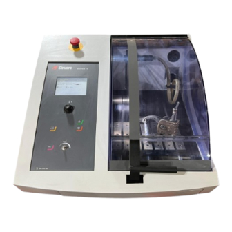
- Page 12 Secotom-15 Instruction Manual Take a moment to familiarise yourself with the location and names of Getting Acquainted with the Secotom-15 components. Secotom-15 Emergency Stop Control panel (details in section 2. Basic Operation) ...
- Page 13 Secotom-15 Instruction Manual MAIN SWITCH The main switch is located on the right hand side of Labotom-5. Turn clockwise to switch on the power. EMERGENCY STOP - Push the red button to Activate. - Turn the red button clockwise to Release.
- Page 14 Secotom-15 Instruction Manual Rear of Secotom-15 Ventilation Flange for Exhaust Type Plate Mains connection Main switch Service socket...
- Page 15 Incorrect voltage may result in damage to the electrical circuit. The Secotom-15 is shipped with 2 types of Mains cables: Single-phase Supply The 2-pin (European Schuko) plug is for use on single-phase, 200-240 V connections.
- Page 16 Secotom-15 Instruction Manual Lift the cover to the "open" position (the position where it will Mounting the Cut-off Wheel stay up and open when released). Note Mind the protruding safety catch when the cover is raised. Lift the cooling fluid nozzles to gain access to the cut-off wheel mounting.
- Page 17 Secotom-15 Instruction Manual Important When mounting cut-off wheels with a 12.7 mm centre hole, make sure that the 22 mm spindle insert has been removed. Failure to do this will result in the cut-off wheel being pressed out of shape.
- Page 18 Secotom-15 Instruction Manual The Secotom-15 has a built-in cooling fluid system. The fluid coming Filling the Cut-off Machine from the nozzles passes over the cut-off wheel and collects in the with Cooling Fluid drain in the cutting chamber; where it then returns to the tank, which is located under the cutting chamber.
- Page 19 Maintain the correct concentration of Struers additive in the cooling water (percentage stated on the container of the Additive). • Remember to add Struers additive each time you refill with water. • It is recommended to change the cooling water at least once a month to prevent the growth of microorganisms.
- Page 20 Secotom-15 Instruction Manual The Secotom-15 is fitted with a moving cutting table. Movement of Cutting Table the table is controlled using the joystick on the Control Panel and through the software, which is described in section 2. Basic Operation. The table has several 8 mm T-slots, which are used to secure clamping tools.
- Page 21 Instruction Manual There are several types of clamping tools available as accessories Attaching Clamping Tools (please refer to the Secotom-15/-50 brochure for details of the range (accessories) available). Some of these are mounted directly on the cutting table while others with more sophisticated features, need to be fixed on a stand using a dovetail holder.
- Page 22 Secotom-15 Instruction Manual Stands for Specimen Holders Place the stand on the cutting table by sliding the securing bolts in the T-slot and tighten the nuts. For stands requiring an electrical supply: Connect the cable as described in...
- Page 23 Connect the accessory to the electrical connection socket. Note The different electrical accessories can be exchanged while Secotom-15 is switched on. Important The plugs on these accessories provide specific pin connections. If for some reason you have a problem with a connection, do not attempt to change the connections in the clamping tool plugs or connection socket.
- Page 24 Secotom-15 Instruction Manual The Secotom-15 comes complete with a flushing system. This Flushing Hose enables the cutting chamber to be rinsed clean of any debris discarded during the cutting process. Flushing is operated through the Control Panel buttons. CAUTION Avoid skin contact with the additive for cooling fluid.
- Page 25 Secotom-15 Instruction Manual Struers recommends the use of an exhaust system as workpieces Connection to an External may emit harmful gases when cut. The unit is prepared for Exhaust System connection to an exhaust system via a 50 mm fitting at the rear of the cabinet.
- Page 26 Secotom-15 Instruction Manual 2. Basic Operation Control Panel...
- Page 27 Secotom-15 Instruction Manual Control Panel This provides information about the individual buttons on the control panel of the Secotom-15. Function Function Multifunction knob Move up- or downwards to Turn/Push Joystick Turn knob to move the cursor ↵ position the cutting table knob or to adjust settings.
- Page 28 Switching on for the first time machine. The following display will appear briefly: The display will then change to the last screen shown before the Secotom-15 was switched off. When switching on Secotom-15 for the first time, the Select language screen will appear. ...
- Page 29 Secotom-15 Instruction Manual You will now be prompted to set the time. Turn knob to select and to adjust the settings. Push knob to accept the settings. You will now be prompted to set the date.
- Page 30 Secotom-15 Instruction Manual Depending on the type of value, there are two different ways of Changing/Editing Values editing. Numeric Values Turn knob to select the value to be changed, e.g. Wheel speed: Push knob to edit the value.
- Page 31 Secotom-15 Instruction Manual Turn knob to select the correct choice. Push knob to accept the new selection and to continue or to return to the previous screen. (Pressing Esc aborts the changes, preserving the original setting.)
- Page 32 Secotom-15 Instruction Manual The Main menu is the highest level in the menu structure. From this Main menu menu, you can enter the Cutting methods, Maintenance and Configuration menus.
- Page 33 Secotom-15 Instruction Manual Cutting methods Editing Cutting methods: Turn knob to select the cutting method to be edited, Method A in this example. Push knob to edit the method. Turn knob to select the parameter to be edited e.g. Cut-off ...
- Page 34 Secotom-15 Instruction Manual Recommended rotation speed (rpm) for the cut-off wheels will also be visible in the cutting menu. Changes made to the cutting method will automatically be saved. To re-set to default values, see the section on Maintenance.
- Page 35 Secotom-15 Instruction Manual Return position There are three available options for the position the cut-off wheel will return to after the cutting process is complete: Start position: Cutting table returns to the start position. Zero position: Cutting table returns to zero position.
- Page 36 Secotom-15 Instruction Manual The Maintenance menu has three under menus. Maintenance Service information: Information regarding the equipment, mainly to be used in connection with service. Reset configuration: Resets all parameters in the Configuration menu to default values. Reset methods & database:...
- Page 37 Secotom-15 Instruction Manual Configuration The Configuration menu contains the parameters which apply to all methods.
- Page 38 Secotom-15 Instruction Manual When the manual X-stand is connected a read out for the x-position Manual X-stand, accessory will appear on the display. X-position can be reset for easy cutting of a specific width. When the rotary stand is connected a read out for the chuck mode Rotary stand, accessory and the x-position will appear on the display.
- Page 39 Secotom-15 Instruction Manual There are three options available in chuck mode: Off: The specimen holder will not turn. (Note: Chuck mode must be set to Off before ExciCut can be selected) Continuously: The specimen holder will turn round continuously in the same direction as the cut-off wheel.
- Page 40 Secotom-15 Instruction Manual Secure the work piece on the cutting table. Starting the Position the cutting table in the correct place. Cutting Process Ensure that the cooling fluid nozzles are lowered into position. Lower the cover (the machine cannot be started before the cover is down).
- Page 41 Secotom-15 Instruction Manual 3. Maintenance To ensure a longer lifetime for your Secotom Struers strongly General Cleaning recommends daily cleaning of the cutting chamber. Clean the cutting chamber thoroughly if the Secotom is not to be used for a longer period of time.
- Page 42 Refill if necessary. Replace the cooling fluid if it appears dirty (build up of cutting debris). Remember to add Struers additive, Corrozip. To check the concentration of additive, use a refractometer. Please see the instructions for use on the label.
- Page 43 Start a cutting process. Activate the Emergency-stop. If cutting does not stop, press STOP and contact Struers Service. Open the cover. Press start.
- Page 44 Secotom-15 Instruction Manual Maintenance of Important Clamping Devices It is recommended to thoroughly clean and lubricate the Quick Clamping Device and Vertical Quick Clamping Device at regular intervals. Adjusting the Clamping Column Maintenance of the Clamping Devices is part of the regular yearly Struers Service.
- Page 45 Secotom-15 Instruction Manual The stainless steel bands (available as spare parts) should be Maintenance of Cutting Tables replaced if damaged or worn. Turning or Replacing Steel During normal use, it is not uncommon for the cutting table steel bands located on either side of the cutting area to be damaged. If Bands on the Cutting Table the bands are only damaged on one side, then they can be turned.
- Page 46 Secotom-15 Instruction Manual Reference Guide Table of Contents Page 1. Struers Knowledge .............. 47 1. Accessories ................48 2. Consumables ................ 48 3. Trouble-Shooting ..............49 4. Service Service Information ................. 56 Changing Cooling Pump Tubes ............57 Tube for Water-free Cooling Fluid .......... 59 5.
- Page 47 Secotom-15 Instruction Manual 1. Struers Knowledge Materialographic sectioning is where most microstructure analysis begins. A good understanding of the abrasive cutting process can help to select suitable clamping and cutting methods and thereby ensure the high quality cut. Minimizing cutting artefacts will help the remaining materialographic process and act as a good base for efficient and high quality preparation.
- Page 48 The warranty may not cover damaged machine parts (e.g. seals and tubes), where the damage can be directly related to the use of non-Struers consumables. Cut-off Wheels Please refer to the Selection Guide in the Struers Cut-off Wheels brochure.
- Page 49 #106 Machine failed during Power-On A critical error is detected during Re-start. Self Testing. Power-On Self Testing. If error remains, contact Struers Please try to restart the machine. The machine will not start. Service. If problem persists please contact Struers technical support.
- Page 50 Cutting process. Alarm register: xxxx If this does not help, contact Error register: xxxx Struers Service and quote the Alarm and Error register values. #128 Open safety lock detected. Sensors register that the safety Check that the cover is closed and Process halted! lock is open during cutting.
- Page 51 Explanation Action Required Errors #001 SMM not present! Struers Memory Module isn't Re-start. correctly connected to machine. If error remains, contact Struers Service. #002 Inverter communication failed! Machine isn't able to Re-start. communicate with frequency If error remains, contact Struers inverter.
- Page 52 Secotom-15 Instruction Manual Error Explanation Action Machine Problems No, or insufficient cooling fluid. Level in the cooling fluid tank too Check that there is sufficient water low. in the Cooling fluid tank. Cooling fluid nozzles blocked. Clean the nozzles. Water leaking.
- Page 53 Incorrect clamping of the workpiece. Support the workpiece and clamp it on both sides. e.g. Struers’ Specimen Holder CATAL, which is designed for clamping small, long workpieces on both sides.. Cutting quality differs. Inadequate cooling.
- Page 54 The nut must be tightened properly. Incorrect clamping of the workpiece. Support the workpiece and clamp it on both sides. e.g. Struers’ Specimen Holder CATAL, which is designed for clamping small, long workpieces on both sides.. Cut-off wheel is too hard.
- Page 55 Secotom-15 Instruction Manual Error Explanation Action The specimen is corroded The specimen has been left in the Remove the specimen directly after cutting chamber for too long. cutting. Leave the cutting chamber hood open when you leave the machine. Insufficient additive for cooling fluid.
- Page 56 Secotom-15 Instruction Manual 4. Service Struers recommends that a regular service check be carried out after Service Information every 1500 hours of use. Struers offers a range of comprehensive maintenance plans to suit the requirements of our customers. This range of services is called ServiceGuard.
- Page 57 Secotom-15 Instruction Manual To exchange the tube: Changing Cooling Pump Tubes Remove the four screws on the protection plate on the rear of the machine. Remove the three screws on the cover on the cooling pump.
- Page 58 Secotom-15 Instruction Manual Remove the tube from the pump axle. Pump axle Loosen the hose clamp and carefully remove the tube ends from the connectors. Attach the new tube to the connectors and tighten the hose clamp (the hose clamp should be on the end of the tube that directs water/cooling fluid into the cutting chamber, as this will have the greatest pressure –...
- Page 59 Secotom-15 Instruction Manual Too loose Too tight Excess volume between The tube is stretched; the rollers will press lifetime of the tube will "waves" of fluid which be reduced. will stretch the tube; lifetime of the tube will be reduced.
- Page 60 Secotom-15 Instruction Manual 5. Technical Data Subject Specifications Motor 0.8 kW Cutting Voltage/frequency Max. load 1 x 220 – 240 V / 50 - 60 Hz 11.7 A Cutting Power 0.8 kW 1.0 kW Cut-off wheels 75 mm (3") - 203 mm (8") dia.
- Page 61 Secotom-15 Instruction Manual Quick Reference Mounting the Cut-off Wheel Lift the cooling fluid nozzles. Insert the stop pin into the hole of the inner flange. Loosen the flange screw. Remove the outer flange. Mount the cut-off wheel and remount the outer flange, with the machined face towards the inner flange.
- Page 62 Secotom-15 Instruction Manual Close the cover. Starting the Choose a cutting method and set/check the cutting parameters. Cutting Process Use the Turn/Push knob to select and change the values. Start the cutting process by pressing START .
- Page 63 Director of Business Development Struers ApS Pederstrupvej 84 Date of Issue: 2017.10.05 DK-2750 Ballerup, Denmark For other language versions, please visit Struers.com. Doc. No.: 15997901 For machines produced before the Date of Issue, please contact your Struers supplier. Rev.: A...
- Page 64 Pederstrupvej 84 DK-2750 Ballerup Denmark...
- Page 65 Secotom-15/-50 Spare Parts and Diagrams Manual No.: 15997001 Revision A Date of Release 2017. 12.04...
- Page 66 The manual may mention accessories or parts not included in the present version of the equipment. The contents of this manual are the property of Struers. Reproduction of any part of this manual without the written permission of Struers is not allowed.
- Page 67 Absorber assembly ............15990034G Damper assembly ............15990074D Diagrams Block diagram Secotom-15/-50 ........15993050C Circuit diagram Secotom-15/-50 (3 pages) ...... 15993100H Wiring Diagram Secotom-15/-50 (6 pages) .......15993450D Some of the drawings may contain position numbers not used in connection with this manual.
- Page 68 To check the availability of other replacement parts, please contact your local Struers Service Technician. It may help identify the part by referral to its position number on the assembly drawings included in this manual.
- Page 69 Secotom-15/-50 Spare Parts and Diagrams Spare Part List for Secotom-15/-50 Drawing Pos. Spare Part Ref. Cat no. 15990012 Cabinet design 50, complete Lid assembly 15990016 Cooling nozles 15990021 Sealing strip Grey 2x5, 0.9m 2IP10202 Sealing strip Grey 2x5, 0.45m 2IP10202...
- Page 70 Secotom-15/-50 Spare Parts and Diagrams Spare Part List for Secotom-15/-50 Drawing Pos. Spare Part Ref. Cat no. Hose Danflex K-126 ø51, 1.5 m 2NU30251 Worm hose clamp 40-60/9.0-C6W2 2NS24060 Mains ca. 1.5mm², C19-Schuko 2WC04680 Mains ca. AWG14, C19-Nema 6-15 2WC02530...
- Page 71 o l l i å r ø l d i o i t t i n t i n : e l : . t i r c e l l...
- Page 72 l i s n i l i r t a i t y l l n i t l l i f l i o c i l l i S h t i l l e n i t , n i c i r y t i...
- Page 73 o i t t i n t i n : l a : e l : . t o i t e l l...
- Page 74 l i r n i l l i r n i l l i r n i l e l l æ æ l i r n i l ± l i S o i t t i n t i n : l a : e l : .
- Page 75 l f a . l e c i l . e l i å æ v i l g i l i å ø . e j t i f n i t g i t k i t å e j f i t c c i t...
- Page 76 h t i i l i l y r i l i c i l c i l o i t t i n t i n : l a : e l l y r : . t o i t e l l...
- Page 77 y l i æ å > - e t i o i t t i n t i n : l a : e l o i t e l l...
- Page 78 l i F h t i o i t t i n t i n : l a : e l : . t o i t e l l...
- Page 79 y t i . t s o i t t i n t i n : l a : e l : . t o i t e l l...
- Page 80 i t c o i t t i n t i n : l a : e l : . t o i t e l l...
- Page 81 n i t c r i t i u o i t t i n t i n : l a : e l : . t o i t e l l...
- Page 82 a l i o i t t o l l l u . l e o i t t i n t i n : l a : e l : . t o i t e l l...
- Page 83 o i t t i n t i n : l a : e l : . t o i t e l l...
- Page 84 Å ü l e l l g i l y l t r i f n i l s i t s i l o i t t i n t i n : l a : e l : . t o i t e l l...
- Page 85 ± c r i t i u ± o i t t i n t i n : l a : e l : . t o i t e l l...
- Page 86 o i t t i n t i n : l a : e l : . t o i t e l l l i t...
- Page 87 n i l h t i . l o n i l l l a n i l i l i n i l i l i n i l . t i a l f æ r ø æ n i l i l i t l e...
- Page 88 o i t t i n t i n : l a : e l o i t e l l...
- Page 89 o i t t i n t i n : l a : e l o i t e l l...
- Page 90 s i l o i t t i n t i n : l a : e l : . t o i t e l l...
- Page 91 3 x Analog Input 5V, YS1.1 JOYSTICK 5VDC Supply for joystick Door Guard (3 axis) Switch 24V-3 input Secotom-15...only Y movement (Emergency Stop + Door closed) Door Guard YS1.2 (shown with Lock door open) Output, 24VDC / 500mA (24V-1 chain)
- Page 92 (shown cable 5 x AWG28 door open) unlocked) Matrix Keyboard X12-1 Y-TABLE MOVEMENT UNIT TYPE INFO START STOP WATER X8-8 X12-5 Address CONN. FOR STRUERS X1-6 X1-6 X3-6 CAN_L X8-3 CAN-LOW X12-7 switch MEMORY MODULE Sec.-15 GN/WH X1-5 X2-1 X1-5...
- Page 93 7 x 0,75mm² X1-1 Stepper Motor Unit LASER 24V Prot. 2 x 0,25mm² cable 2 x 0,5mm² Laser STRUERS A/S light OHO (2010-08-24) - REV B Pederstrupvej 84 - wiring of X table updated DK-2750 Ballerup OHO (2011-09-23) - REV D Denmark...
- Page 94 Safe Torque Off door open) unlocked) function Main AC Motor 3 x PT100 Frequency Inverter XPE3 Secotom-50...1500W Secotom-15...1100W BASE PLATE Secotom-50...1100W Secotom-15...750W STRUERS A/S OHO (2011-09-23) - REV D Pederstrupvej 84 - page 3 (Safety Related Circuits) created DK-2750 Ballerup...
- Page 95 X1 to A1 (Page 3) X26 to M2 (Page 4) X17 to A2 (Page 2) X15 to X51 (Page 5) X11 to X52 (Page 3) STRUERS A/S CZO (2016-05-27) - REV B Pederstrupvej 84 - See changes on Page 6 DK-2750 Ballerup...
- Page 96 W18 / X103 to A4:X4 (Page 1) Z1 to X100:1 (Page 5) Z1 to X100:2 (Page 5) A2:XPE3 to XPE3 (Page 3) Z1:XPE2 to XPE2 (Page 3) STRUERS A/S CZO (2016-05-27) - REV B Pederstrupvej 84 - See changes on Page 6 DK-2750 Ballerup...
- Page 97 (Page 4) Pump COLOR CODE: ------------------------ BK = black BN = brown RD = red STRUERS A/S CZO (2016-05-27) - REV B Pederstrupvej 84 OG = orange - See changes on Page 6 DK-2750 Ballerup CZO (2016-08-16) - REV C...
- Page 98 A1 A2 21 Secotom-50 only W12 W11 W10 (to X52 Page 3) Pump Motor A5 (F) STRUERS A/S CZO (2016-05-27) - REV B Pederstrupvej 84 - See changes on Page 6 DK-2750 Ballerup CZO (2016-08-16) - REV C Denmark - See changes on Page 6...
- Page 99 GY = grey WH = white PK = pink BE = beige RO = rose YEGN = yellow-green STRUERS A/S CZO (2016-05-27) - REV B Pederstrupvej 84 - See changes on Page 6 DK-2750 Ballerup CZO (2016-08-16) - REV C...
- Page 100 PK = pink L... BE = beige M... RO = rose YEGN = yellow-green (Optional laser) STRUERS A/S CZO (2016-05-27) - REV B Pederstrupvej 84 - Connector X112 added DK-2750 Ballerup CZO (2016-08-16) - REV C Denmark - Wire colour for X-table change...
- Page 101 Secotom-15/-50 Spare Parts and Diagrams...
- Page 102 Pederstrupvej 84 DK-2750 Ballerup Denmark...
Need help?
Do you have a question about the Secotom-15 and is the answer not in the manual?
Questions and answers