Table of Contents
Advertisement
Quick Links
Advertisement
Table of Contents

Related Manuals for Neousys Technology POC-700-FT Series


Summary of Contents for Neousys Technology POC-700-FT Series
- Page 1 Neousys Technology Inc. POC-700 Series POC-700-FT Series User Manual Revision 1.2...
-
Page 2: Table Of Contents
Table of Content Table of Contents Table of Contents ........................2 Legal Information ........................4 Contact Information ....................... 5 Declaration of Conformity ..................... 5 Copyright Notice ........................6 Safety Precautions ......................... 7 Service and Maintenance ...................... 8 ESD Precautions ........................8 About This Manual ......................... - Page 3 Table of Content Installing Internal Components ................54 3.2.1 DDR5 SO-DIMM Installation ................54 3.2.2 M.2 2880 M Key SSD Installation ..............56 3.2.3 mini-PCIe Module, SIM Card and Antenna Installation ........58 ® 3.2.4 MezIO Module Installation ................62 Installing the System Enclosure ................
-
Page 4: Legal Information
For questions in regards to hardware/ software compatibility, customers should contact Neousys Technology Inc. sales representative or technical support. To the extent permitted by applicable laws, Neousys Technology Inc. shall NOT be responsible for any interoperability or compatibility issues that may arise when (1) products, software, or options not certified and supported;... -
Page 5: Contact Information
3384 Commercial Avenue, Northbrook, IL 60062, USA (Illinois, USA) Tel: +1-847-656-3298 Email, Website China Neousys Technology China Co., Ltd. Room 612, Building 32, Guiping Road 680, Shanghai Tel: +86-2161155366 Email, Website Declaration of Conformity This equipment has been tested and found to comply with the limits for a Class A digital device, pursuant to part 15 of the FCC Rules. -
Page 6: Copyright Notice
This manual is intended to be used as an informative guide only and is subject to change without prior notice. It does not represent commitment from Neousys Technology Inc. Neousys Technology Inc. shall not be liable for any direct, indirect, special, incidental, or consequential damages arising from the use of the product or documentation, nor for any infringement on third party rights. -
Page 7: Safety Precautions
Safety Precautions Safety Precautions ⚫ Read these instructions carefully before you install, operate, or transport the system. ⚫ Install the system or DIN rail associated with, at a sturdy location ⚫ Install the power socket outlet near the system where it is easily accessible ⚫... -
Page 8: Service And Maintenance
Service and Maintenance/ ESD Precautions Service and Maintenance ⚫ ONLY qualified personnel should service the system ⚫ Shutdown the system, disconnect the power cord and all other connections before servicing the system ⚫ When replacing/ installing additional components (expansion card, memory module, etc.), insert them as gently as possible while assuring proper connector engagement ESD Precautions... -
Page 9: About This Manual
This manual introduces and demonstrates installation procedures of Neousys POC-700 series systems featuring an Intel® Core™ i3-N305 or Atom® x7425e processor. The manual also demonstrates the system’s general installation procedures. Revision History Version Date Description Oct. 2023 Initial release Apr. 2024 Updated specifications Sep. 2024 Added POC-700-FT series... -
Page 10: Introduction
POC-500 series with identical footprint. The flat heatsink design of POC-700-FT series measures approximately 52 x 116 x 176 mm, reducing the overall size up to 30%, allowing it to fit into more compact spaces. -
Page 11: Specification Of Poc-715/ Poc-715-Ft
POC-700/ POC-700-FT Series Specification of POC-715/ POC-715-FT System Core Intel® Alder Lake CoreTM i3-N305 processor (8C/8T, 1.8/3.8 GHz, Processor 15W TDP) Graphics Integrated Intel® HD Graphics with 32EUs Memory Up to 16 GB DDR5-4800 SDRAM (one SODIMM socket) Supports dTPM 2.0... - Page 12 POC-700/ POC-700-FT Series Environmental Operating -25°C to 70°C* temperature Storage -40°C to 85°C temperature Humidity 10% to 90% , non-condensing MIL-STD-810H, Method 514.8, Category 4 Vibration Shock MIL-STD-810H, Method 516.8, Procedure I CE/ FCC Class A, according to EN 55032 & EN 55035...
-
Page 13: Specification Of Poc-712/ Poc-712-Ft
POC-700/ POC-700-FT Series Specification of POC-712/ POC-712-FT System Core Processor Intel® Atom® x7425E Integrated Intel® HD Graphics 24EUs Graphics Memory Up to 16 GB DDR5-4800 SDRAM (one SODIMM socket) Supports dTPM 2.0 Panel I/O Interface Ethernet 4x Gb Ethernet ports by Intel® I350-AM4... - Page 14 POC-700/ POC-700-FT Series Storage -40°C to 85°C temperature Humidity 10% to 90% , non-condensing MIL-STD-810H, Method 514.8, Category 4 Vibration Shock MIL-STD-810H, Method 516.8, Procedure I CE/ FCC Class A, according to EN 55032 & EN 55035 UL 62368-1, IEC 62368-1 (UL series only) Safety * For sub-zero and over 60°C operating temperature, a wide temperature Solid State...
-
Page 15: Dimension Of Poc-700
POC-700/ POC-700-FT Series Dimension of POC-700 NOTE All measurements are in millimeters (mm). 1.3.1 POC-700 Front Panel View... -
Page 16: Reserved Panel View
POC-700/ POC-700-FT Series 1.3.2 POC-700 Reserved Panel View 1.3.3 POC-700 COM Port Panel View... -
Page 17: Bottom View
POC-700/ POC-700-FT Series 1.3.4 POC-700 Bottom View... -
Page 18: Dimensions Of Poc-700-Ft
POC-700/ POC-700-FT Series Dimensions of POC-700-FT NOTE All measurements are in millimeters (mm). 1.4.1 POC-700-FT Front Panel View... -
Page 19: Poc-700-Ft Reserved Panel View
POC-700/ POC-700-FT Series 1.4.2 POC-700-FT Reserved Panel View 1.4.3 POC-700-FT COM Port Panel View... -
Page 20: Poc-700-Ft Bottom View
POC-700/ POC-700-FT Series 1.4.4 POC-700-FT Bottom View... -
Page 21: System Overview
Upon receiving and unpacking your POC-700 systems, please check immediately if the package contains all the items listed in the following table. If any item(s) are missing or damaged, please contact your local dealer or Neousys Technology. Unpacking the System... -
Page 22: Series Front Panel
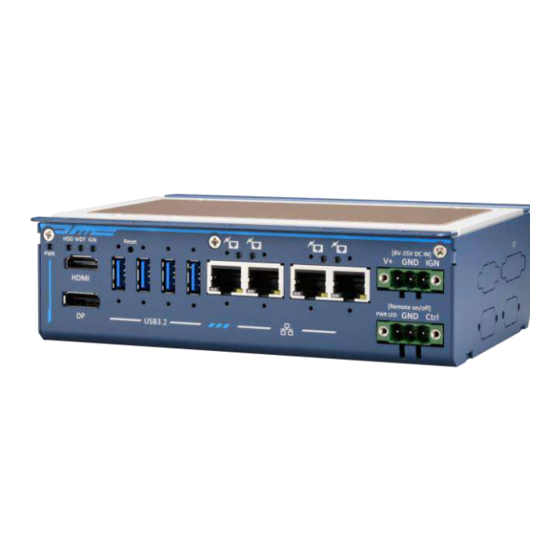
The POC-700 and POC-700-FT share the same I/O ports, therefore POC-700 will be shown here for demonstration purposes. The front panel of POC-700/ POC-700-FT series features four PoE+ Gigabit Ethernet ports, four USB 3.1 Gen1 ports, one DisplayPort, one HDMI port, remote control and 3-pin terminal block for DC input. -
Page 23: System Status Led
POC-700/ POC-700-FT Series 2.2.1 System Status LED There are three LED indicators on the front panel: HDD, WDT and IGN. The descriptions of these LEDs are listed in the following table. Indicator Color Description Green Power indictor, lit when system is on. -
Page 24: Hdmi
POC-700/ POC-700-FT Series 2.2.2 HDMI The High-Definition Multimedia Interface (HDMI) port provides uncompressed high-quality digital video and audio transmission between the system and a multimedia display device on a single cable. You can connect to other digital inputs by using a HDMI-to-DVI or HDMI-to-DP cable. -
Page 25: Displayport
POC-700/ POC-700-FT Series 2.2.3 DisplayPort The system has a DisplayPort (DP) output which is a digital display interface that mainly connect video source and carry audio to a display device. When connecting a DP, it can deliver up to 4K UHD (4096 x 2160 @ 60Hz) in resolution. The system is designed to support passive DP adapter/ cable. -
Page 26: Reset Button
POC-700/ POC-700-FT Series 2.2.4 Reset Button The reset button is used to manually reset the system in case of system halt or malfunction. To avoid unexpected reset, the button is purposely placed behind the panel. To reset, please use a pin-like object (eg. tip of a pen) to access the reset button 2.2.5... -
Page 27: Ieee 802.3At Power Over Ethernet Port
POC-700/ POC-700-FT Series 2.2.6 IEEE 802.3at Power over Ethernet Port The system offers four Gb Ethernet ports via Intel® I350-AM4 and is backward compatible with 100/ 10Mb connection speeds. The Gigabit Power over Ethernet (PoE) port is only available on POC-715 system that can supply power and data on a standard CAT-5/CAT-6 Ethernet cable. -
Page 28: 3-Pin Terminal Block For Dc Input (Optional Ignition Input)
POC-700/ POC-700-FT Series 2.2.7 3-pin Terminal Block for DC Input (Optional Ignition Input) The system accepts a wide range of DC power input from 8V to 35V or 12V to 35V (UL series) via a 3-pin pluggable terminal block, which is fit for field usage where DC power is usually provided. -
Page 29: 3-Pin Remote On/ Off
POC-700/ POC-700-FT Series 2.2.8 3-pin Remote On/ Off The “Remote On/ Off” 3-pin connection allows for external switch extension. It is useful when the system is placed in a cabinet or a not easily accessed location. You may connect an external remote with an external status LED indicator (15mA) by... -
Page 30: Dio/ Com Port Panel
POC-700/ POC-700-FT Series DIO/ COM Port Panel The COM port panel of POC-700 series features additional I/O functions, such as digital input/ output, COM ports, and reserved antenna openings for SMA antenna installation. In addition, the power button can also be located on this panel. -
Page 31: Digital Input/ Output
POC-700/ POC-700-FT Series 2.3.1 Digital Input/ Output The system provides 4x isolated digital input channels and 4x isolated digital output channels. The DIO functions support polling mode I/O access and DI change-of-state interrupt. Please refer to Watchdog Timer & Isolated DIO information on wiring and programming the isolated DIO channels. - Page 32 POC-700/ POC-700-FT Series Wiring for DIO The digital input function is implemented using a photo-coupler with an internally series-connected 1kΩ resistor. You need to provide a voltage to specify the logic high/low state. The input voltage for logic high is 5~24V, and the input voltage for logic low is 0~1.5V.
-
Page 33: Com 1 Port
POC-700/ POC-700-FT Series 2.3.2 COM 1 Port Implemented using industrial-grade ITE8786 Super IO chip (-40 to 85°C) and provide up to 921600 bps baud rate, COM1 is a software-configurable RS-232/422/485 port via 9-pin D-Sub male connector. The operation mode, slew rate and termination of COM1 can be set in BIOS setup utility. -
Page 34: Com Port (Com2/ Com3/ Com4)
POC-700/ POC-700-FT Series 2.3.3 COM Port (COM2/ COM3/ COM4) Implemented using industrial-grade ITE8786 Super IO chip (-40 to 85°C) and provide up to 921600 bps baud rate, the D-Sub male connector (COM2/ 3/ 4) can be configured in the BIOS as single RS-422/ 485 port (COM2) or three 3-wire RS-232 ports (COM2/COM3/COM4). -
Page 35: Power Button
POC-700/ POC-700-FT Series 2.3.4 Power Button The power button is a non-latched switch for ATX mode on/off operation. Press to turn on the system, PWR LED should light up and to turn off, you can either issue a shutdown command in the OS, or just press the power button. In case of system halts, you can press and hold the power button for 5 seconds to force-shutdown the system. -
Page 36: Sma Antenna Opening
POC-700/ POC-700-FT Series 2.3.5 SMA Antenna Opening The system offers three SMA antenna openings reserved for SMA antenna installations. Users can take advantage of these three openings when installing mini-PCIe module for wireless communication reception such as 3G, 4G, GPS or... -
Page 37: Cmos Reset Button
POC-700/ POC-700-FT Series CMOS Reset Button Positioned on the rear panel (opposite the IO panel), indicated by the blue arrow, the CMOS Reset button is used to manually reset the motherboard BIOS in case of system halt or malfunction. To avoid unexpected operation, it is purposely placed behind the panel. -
Page 38: Reserved Port Opening Panel
POC-700/ POC-700-FT Series Reserved Port Opening Panel The reserved port opening panel has reserved openings for DIO or extra COM ports. Choose from a wide range Neousys' MezIO modules and find one that best suit your needs. -
Page 39: Internal I/O
POC-700/ POC-700-FT Series Internal I/O The system’s internal I/O connectors consist of an mini-PCIe slot with SIM slot, an M.2 slot for NVMe SSD, SO-DIMM socket, slot and a MezIO port for application-oriented expansion purposes. 2.6.1 Full-size mini-PCIe Slot and SIM Socket The system provides a full-size mini-PCIe socket (indicated in blue) designed with SIM card (indicated in red) support. - Page 40 POC-700/ POC-700-FT Series mini-PCIe Pin Definition Pin # Signal Pin # Signal WAKE# +3.3Vaux COEX1 COEX2 +1.5V CLKREQ# UIM_PWR UIM_DATA REFCLK- UIM_CLK REFCLK+ UIM_RESET UIM_VPP Mechanical Key Reserved* (UIM_C8) Reserved* (UIM_C4) W_DISABLE# PERST# PERn0 +3.3Vaux PERp0 +1.5V SMB_CLK PETn0 SMB_DATA...
-
Page 41: 2280 (M Key) Slot For Ssd
POC-700/ POC-700-FT Series 2.6.2 M.2 2280 (M Key) Slot for SSD The system has an M key M.2 2280 slot supporting PCIe Gen3 x1 signal for NVMe SSD storage, and it also supports SATA signal for SATA SSD. Users can install an SSD for improved disk read/ write performance over mechanical hard drives or 2.5”... - Page 42 POC-700/ POC-700-FT Series M.2 (M Key) Slot Pin Definition Pin # Signal Pin # Signal +3V3 +3V3 PERN3 PERP3 DAS/DSS_N PETN3 +3V3 PETP3 +3V3 +3V3 PERN2 +3V3 PERP2 PETN2 PETP2 PERN1 PERP1 PETN1 PETP1 PERn0 / SATA-B+ PERp0 / SATA-B-...
-
Page 43: So-Dimm Socket
POC-700/ POC-700-FT Series 2.6.3 SO-DIMM Socket The system supports one SO-DIMM socket for installing DDR5-4800 memory module up to 16GB in capacity. -
Page 44: Mezio ® Interface
POC-700/ POC-700-FT Series ® MezIO Interface MezIO ® is an innovative interface designed for integrating application-oriented I/O functions into an embedded system. It offers computer signals, power rails and ® control signals via a high-speed connector. MezIO is also mechanically reliable ®... -
Page 45: Mezio Interface Pin Definition
POC-700/ POC-700-FT Series ® 2.7.1 MezIO Interface Pin Definition ® ® MezIO interface leverages FCI BERGSTAK board-to-board connector to provide interconnectivity of high-speed signals. The receptacle part on the PCBA is FCI ® 61082-063402LF while the plug part on the MezIO module is FCI 61083-064402LF. -
Page 46: Mezio Modules For Poc-700 Series
POC-700/ POC-700-FT Series ® 2.7.2 MezIO Modules for POC-700 Series Neousys offers MezIO ® modules to expand I/O functions for Neousys systems. With ® the addition of a MezIO module into your system, it offers extra RS-232/ 422/ 485 ports, isolated digital I/ O, 2.5” HDD/ SSD accommodation or ignition power control. -
Page 47: System Installation
POC-700/ POC-700-FT Series System Installation Before disassembling the system enclosure and installing components and modules, please make sure you have done the following: ⚫ It is recommended that only qualified service personnel should install and service this product to avoid injury or damage to the system. -
Page 48: Disassembling The System Enclosure
POC-700/ POC-700-FT Series Disassembling the System Enclosure 3.1.1 Disassembling POC-700 To install internal components such as M.2 SSD, memory module, mini-PCIe or ® MezIO module, you need to disassemble the system enclosure. Please refer to the following procedures: Remove the three (3) screws on the front I/O panel. - Page 49 POC-700/ POC-700-FT Series Remove the two (2) screws on the read panel. Remove the four (4) hex bolt screws on the DIO/ COM port panel. Separate the IO and bottom panel from the system Remove front IO panel Remove bottom panel...
- Page 50 POC-700/ POC-700-FT Series Unscrew the two (2) screws to remove the DRAM/ M.2 heat spreader. With external panels and DRAM/ M.2 heat spreader removed, you are ready to install internal components. Reinstall the enclosure when done.
-
Page 51: Disassembling Poc-700-Ft
POC-700/ POC-700-FT Series 3.1.2 Disassembling POC-700-FT NOTE Please place the system on a flat and sturdy surface to avoid damaging the thermal pad. To install internal components such as M.2 SSD, memory module, mini-PCIe or ® MezIO module, you need to disassemble the system enclosure. Please refer to the following procedures: Remove the three (3) screws on the front I/O panel. - Page 52 POC-700/ POC-700-FT Series Remove the two (2) screws on the read panel. Remove the four (4) hex bolt screws on the DIO/ COM port panel. Separate the IO and bottom panel from the system Remove front IO panel Remove reserved punch-out panel...
- Page 53 POC-700/ POC-700-FT Series Remove the bottom panel. Unscrew the two (2) screws to remove the DRAM/ M.2 heat spreader. With external panels and DRAM/ M.2 heat spreader removed, you are ready to install internal components. Reinstall the enclosure when done.
-
Page 54: Installing Internal Components
POC-700/ POC-700-FT Series Installing Internal Components 3.2.1 DDR5 SO-DIMM Installation There is one SO-DIMM memory slot on the motherboard. Please follow the procedures below to install the memory module. Disassemble the system enclosure. 2. Locate the SO-DIMM slot on the motherboard shown once the enclosure and heat spreader have been removed. - Page 55 POC-700/ POC-700-FT Series 4. Remove the protection film on the thermal pad. 5. Secure the DRAM/ M.2 heatsink spreader onto the side of the system heatsink. Reinstall the enclosure when done.
-
Page 56: 2880 M Key Ssd Installation
POC-700/ POC-700-FT Series 3.2.2 M.2 2880 M Key SSD Installation There is one M.2 2280 M Key slot for you to install an SSD. Please follow the procedures below to install the M.2 SSD module. Disassemble the system enclosure. 2. Located the M.2 2280 M Key slot once the system enclosure and heat spreader have been removed. - Page 57 POC-700/ POC-700-FT Series 4. Gently push it towards the motherboard and secure the NVMe SSD with the supplied screw. 5. Once you have installed the NVMe SSD, you need to reinstall the heat spreader but before you do so, please make sure the protective film on the thermal pads have been removed.
-
Page 58: Mini-Pcie Module, Sim Card And Antenna Installation
POC-700/ POC-700-FT Series 3.2.3 mini-PCIe Module, SIM Card and Antenna Installation There are mini-PCIe with SIM slots on MezIO module and the motherboard. Please follow the procedures below to install the mini-PCIe module and SIM card, as well as the antenna for wireless communication. - Page 59 POC-700/ POC-700-FT Series 4. Flip the holder back onto the SIM card and push in the direction shown to lock-in the SIM card into the slot. 5. To install, insert mini-PCIe module’s gold finger on a 45 degree angle into the socket, gently press the module down and secure it with a screw.
- Page 60 POC-700/ POC-700-FT Series 6. Clip-on mini-PCIe module’s antenna (please refer to the module’s user manual on antenna cable connection). 7. Remove one of the antenna covers from the enclosure.
- Page 61 POC-700/ POC-700-FT Series 8. Secure the SMA antenna connector, reinstall the enclosure and attach the external SMA antenna. Securing antenna connection Attach external antenna Reinstall the enclosure when done.
-
Page 62: Mezio ® Module Installation
POC-700/ POC-700-FT Series ® 3.2.4 MezIO Module Installation ® The MezIO module is situated above the heat spreader. Please make sure that you have installed the memory module, mini-PCIe, SIM card, NVMe SSD before installing the MezIO ® module. To install the MezIO ®... - Page 63 POC-700/ POC-700-FT Series 4. Remove the screws indicated and replace with stand-off hex bolt screws. Hex bolt screw locations Stand-off hex bolt screws...
- Page 64 POC-700/ POC-700-FT Series 5. Gently lower the module onto the motherboard. Install the panel that came with ® the MezIO module you ordered by securing the screw indicated. Remove the corresponding punch out plates (may Secure the screw ® differ depending on your MezIO module) 6.
-
Page 65: Installing The System Enclosure
POC-700/ POC-700-FT Series Installing the System Enclosure 3.3.1 Installing POC-700’s Enclosure Install the bottom/ rear enclosure panel Install the front panel and securing it with three (3) screws. - Page 66 POC-700/ POC-700-FT Series Secure the bottom and rear panel with screws. Bottom panel screws Rear panel screws Secure the hex bolt screws on the DIO/ COM port panel to complete the enclosure installation.
-
Page 67: Installing Poc-700-Ft's Enclosure
POC-700/ POC-700-FT Series 3.3.2 Installing POC-700-FT’s Enclosure NOTE Please place the system on a flat and sturdy surface to avoid damaging the thermal pad. Install the L-shaped bottom/ rear panel. Install the reserved punch-out panel. - Page 68 POC-700/ POC-700-FT Series Assemble the front panel. Secure the front panel with screws indicated.
- Page 69 POC-700/ POC-700-FT Series Secure the bottom with screws indicated. Secure the hex bolt screws on the DIO/ COM port panel to complete the enclosure installation.
-
Page 70: Din Rail Installation
POC-700/ POC-700-FT Series POC-700 DIN Rail Installation The system comes with a DIN rail clip (in the accessory box) that allows the system to be mounted vertically. To install, secure the DIN rail clip (indicated in red) to the rear side panel of the... - Page 71 POC-700/ POC-700-FT Series To install the DIN rail clip onto the DIN rail, you must come over the top of the DIN rail, tilting, overlap the top clip edge of the DIN rail clip onto the DIN rail first, and then firmly press the bottom-front of the enclosure to clip the bottom edge...
- Page 72 POC-700/ POC-700-FT Series Confirm the mount plate has indeed clipped onto the DIN rail for proper fit to complete the installation.
-
Page 73: Horizontal Wall Mount Installation (Optional)
POC-700/ POC-700-FT Series POC-700 Horizontal Wall Mount Installation (Optional) The optional horizontal wall mount bracket allows the system to be mounted horizontally. Please refer to the following installation procedure: Remove the rubber stands to access the M4 tapping (indicated in green). - Page 74 POC-700/ POC-700-FT Series Dimension illustration of the installed horizontal wall mount bracket for your reference.
-
Page 75: Vertical Wall Mount Bracket (Optional)
POC-700/ POC-700-FT Series 3.5.1 POC-700 Vertical Wall Mount Bracket (Optional) To install, secure the vertical wall mount bracket (indicated in red) to the rear panel of the system using the M4 screws provided (indicated in blue). Dimension illustration of the install vertical wall mount bracket for you... -
Page 76: Mounting Poc-700-Ft
POC-700/ POC-700-FT Series Mounting POC-700-FT 3.6.1 Mounting POC-700-FT To mount POC-700-FT, please refer to the following procedure: Note the distances between the screw-holes (indicated in green). Find a flat spot on a metallic surface (eg. Inside of an enclosure wall), position... -
Page 77: Mounting Poc-700-Ft Using Brackets
POC-700/ POC-700-FT Series 3.6.2 Mounting POC-700-FT Using Brackets To mount POC-700-FT using brackets, please refer to the following procedure: The mounting brackets will have the following dimensions, and the area indicated in red is the flattop heatsink contact area. To wall mount POC-700-FT using brackets, you need to secure the system... - Page 78 POC-700/ POC-700-FT Series Find a flat spot on a metallic surface (eg. Inside of an enclosure wall), position the system approximately at the center of the flat surface, and secure with the screws indicated.
-
Page 79: Fan Kit Installation (Optional)
POC-700/ POC-700-FT Series Fan Kit Installation (Optional) The optional fan kit is only applicable to POC-700 system when operating in specific environments. To install the optional fan kit, please refer to the following procedure. Place the fan on top of the system’s heatsink and secure it with the screws (on front and rear panels) and beware of the orientation of the fan as the fan’s... - Page 80 POC-700/ POC-700-FT Series Remove the punch-out panel, insert and connect the power cable. Insert and connect the fan’s power cable Remove the punch-out panel Once the power cable is connected, place the supplied cable cover over the power cable and secure it with screws indicated to complete the installation.
-
Page 81: Powering On The System
POC-700/ POC-700-FT Series Powering On the System There are three methods to power on the system ⚫ Pressing the power button ⚫ Via an external non-latched switch ⚫ Sending a LAN packet via Ethernet (Wake-on-LAN) 3.8.1 Powering On Using the Power Button This is the simplest way to turn on your system. -
Page 82: Powering On Using An External Non-Latched Switch
POC-700/ POC-700-FT Series 3.8.2 Powering On Using An External Non-Latched Switch If your application demands the system to be placed inside a cabinet, you may use an external non-latched switch to power on/ off the system. The system provides a 3-pin “Remote On/ Off”... -
Page 83: Powering On Using Wake-On-Lan
POC-700/ POC-700-FT Series 3.8.3 Powering On Using Wake-on-LAN Wake-on-LAN (WOL) is a mechanism to wake up a computer system from a S3 (standby), S4 (Hibernate) or S5 (system off with standby power) state via issuing Subnet Directed Broadcasts (SDB) or a magic packet. The system implements the Wake-on-LAN function for the GbE ports highlighted in blue, shown below. - Page 84 POC-700/ POC-700-FT Series Click the Power Management tag, and check the following two options accordingly ⚫ Wake on Magic Packet The system can wake from S3 or S4 state when receiving a magic packet. The magic packet is a broadcast frame containing anywhere within its payload 6 bytes of all 255 (FF FF FF FF FF FF in hexadecimal), followed by sixteen repetitions of the target computer's 48-bit MAC address.
- Page 85 POC-700/ POC-700-FT Series 78 D0 04 0A 0B 0C 78 D0 04 0A 0B 0C 78 D0 04 0A 0B 0C 78 D0 04 0A 0B 0C 78 D0 04 0A 0B 0C 78 D0 04 0A 0B 0C 78 D0 04 0A 0B 0C 78 D0 04 0A 0B 0C...
-
Page 86: Bios Settings
POC-700/ POC-700-FT Series BIOS Settings The system is shipped with factory-default BIOS settings optimized for best performance and compatibility. In this section, we’ll illustrate some BIOS settings you may need to set or change prior to operating system installation. Please always make sure you understand the effect of change before you proceed with any changes. -
Page 87: Com1 Port Configuration
POC-700/ POC-700-FT Series COM1 Port Configuration The system’s COM1 port support RS-232 (full-duplex), RS-422 (full-duplex) and RS-485 (half-duplex) mode. You can set the COM1 operating mode via BIOS settings. The option in the BIOS setting called “Slew Rate” defines how sharp the rising/falling edge is for the output signal of COM1. -
Page 88: Com 2/ 3/ 4 Port Configuration
POC-700/ POC-700-FT Series COM 2/ 3/ 4 Port Configuration The system’s COM 2/ 3/ 4 ports support RS-232 (full-duplex). When set to RS-422/485 mode, it will only act as COM2 port only. To enable COM/ 3/ 4 operating mode: Press F2 when the system boots up to enter the BIOS setup utility. -
Page 89: Com Port High Speed Mode
POC-700/ POC-700-FT Series COM Port High Speed Mode The high speed mode of each COM port effectively allows for the port's baud rate generator to operate at 8x the speed with an effective baud rate of 921,600 bps (115,200 x 8). Please refer to the following instructions on how to enable the high speed mode for your COM port (COM1 used as an example). -
Page 90: Tpm Availability
POC-700/ POC-700-FT Series TPM Availability Trusted Platform Module (TPM) is a hardware-based cryptoprocessor to secure hardware by integrating cryptographic keys into devices. The system is designed with on-board TPM 2.0 module. It is enabled in the BIOS by default. To enable TMP availability: When system boots up, press F2 to enter BIOS setup utility. -
Page 91: Power Over Ethernet (Poe)
POC-700/ POC-700-FT Series Power over Ethernet (PoE) The Power over Ethernet (PoE) setting in the BIOS allows you to enable/ disable the PoE function of the designated port upon system boot up. To enable/ disable Power over Ethernet settings: Press F2 when the system boots up to enter the BIOS setup utility. -
Page 92: Wake-On-Lan
POC-700/ POC-700-FT Series Wake-on-LAN Wake-on-LAN (WOL) is a mechanism which allows you to turn on your system via Ethernet connection. To utilize Wake-on-LAN function, you have to enable this option first in BIOS settings. Please refer to Powering on via Wake-on-LAN function. -
Page 93: C-States
POC-700/ POC-700-FT Series C-States Intel processors utilize C-States to regulate the power-draw and operating frequency of each core. By enabling this function, it allows BIOS to reduce the operating frequency, power-draw, or both of the idle processor core for the system to operate more efficiently. - Page 94 POC-700/ POC-700-FT Series Highlight “C states” and press ENTER, set to “Enabled” and press ENTER. Press F10 to “Save and Exit”.
-
Page 95: Power On After Power Failure
POC-700/ POC-700-FT Series Power On after Power Failure This option defines the system’s behavior when DC power is supplied. Value Description S0 – Power On System is powered on when DC power is supplied. S5 – Power Off System is kept in off state when DC power is supplied. -
Page 96: Boot Menu
POC-700/ POC-700-FT Series Boot Menu The Boot menu in BIOS allows you to specify the system’s boot characteristics by setting bootable device components (boot media) and method. Or, you may press F12 upon system start up and select a device you wish boot from. - Page 97 POC-700/ POC-700-FT Series Newly detected boot media are placed at the top Add Boot Options First of the boot order. Newly detected boot media are placed at the Last bottom of the boot order. Newly detected boot media order will be Auto automatically detected and placed in boot order.
-
Page 98: 4.10 Position New Boot Device
POC-700/ POC-700-FT Series 4.10 Position New Boot Device The “Add Boot Options” allow you to determine whether a newly added device (eg. USB flash disk) is to boot as the first device to boot or the last in the boot sequence. -
Page 99: 4.11 Watchdog Timer
POC-700/ POC-700-FT Series 4.11 Watchdog Timer The watchdog timer secures the boot process by means of a timer. Once the timer expires, a reset command is issued to initiate another booting process. There are two options in BIOS menu, “Automatically after POST” and “Manually after Entering OS”. -
Page 100: Os Support And Driver Installation
POC-700/ POC-700-FT Series OS Support and Driver Installation Operating System Compatibility The system supports most operating system developed for Intel® x86 architecture. The following list contains the operating systems which have been tested by Neousys Technology. ⚫ Microsoft Window 10 LTSC 2021 (x64) Microsoft Windows 11 IoT Enterprise 22H2 64-bit ⚫... -
Page 101: Driver Installation
POC-700/ POC-700-FT Series Driver Installation The system drivers are available online, please click on this link to download the drivers. Driver Installation for Watchdog Time Control Neousys provides a driver package which contain function APIs for Watchdog Timer control function. You should install the driver package (WDT_DIO_Setup.exe) in prior to use these functions. -
Page 102: Appendix A Using Wdt & Dio
In this section, we’ll illustrate how to use the function library provided by Neousys to program the WDT functions. Currently, WDT driver library supports Windows 10 x64 and WOW64 platform. For other OS support, please contact Neousys Technology for further information. -
Page 103: Wdt And Dio Library Installation
POC-700/ POC-700-FT Series WDT and DIO Library Installation WDT_DIO_Setup.2.4.0.0.exe will be used as an example to demonstrate WDT & DIO Library installation setup process. Please refer to the instructions below. 1. Execute WDT_DIO_Setup.2.4.0.0.exe. 2. Click “Next >” and specify the directory of installing related files. The default... - Page 104 POC-700/ POC-700-FT Series 3. Once the installation has finished, a dialog will appear to prompt you to reboot the system. The WDT & DIO library will take effect after the system has rebooted. 4. When programming your WDT or DIO program, the related files are located in...
-
Page 105: Wdt Function Reference
POC-700/ POC-700-FT Series WDT Function Reference InitWDT Syntax BOOL InitWDT(void); Description: Initialize the WDT function. You should always invoke InitWDT() before set or start watchdog timer. Parameter None Return Value TRUE: Successfully initialized FALSE: Failed to initialize Usage BOOL bRet = InitWDT() -
Page 106: Startwdt
POC-700/ POC-700-FT Series StartWDT Syntax BOOL StartWDT(void); Description Starts WDT countdown. Once started, the WDT LED indicator will begin blinking. If ResetWDT() or StopWDT is not invoked before WDT countdowns to 0, the WDT expires and the system resets. Parameter... -
Page 107: Dio Functions
POC-700/ POC-700-FT Series DIO Functions InitDIO Syntax BOOL InitDIO(void); Initialize the DIO function. You should always invoke InitDIO() Description before write/read any DIO port/channel. Parameter None Return Value Returns TRUE if initialization successes, FALSE if initialization failed. Usage BOOL bRet = InitWDT() -
Page 108: Dowriteline
POC-700/ POC-700-FT Series DOWriteLine Syntax void DOWriteLine(BYTE ch, BOOL value); Write a single channel of isolated digital output. Description Parameter BYTE value specifies the DO channel to be written. Ch should be a value of 0 ~ 7. value BOOL value (TRUE or FALSE) specifies the status of DO channel. -
Page 109: Appendix B Poe On/ Off Control
POC-700/ POC-700-FT Series Appendix B PoE On/ Off Control The system offers four 802.3at PoE+ ports with a unique feature to allow users manually turn on or off the power supply of each PoE port. This can be function can be useful in power device (PD) fault-recovery or power reset. -
Page 110: Enablepoeport
POC-700/ POC-700-FT Series EnablePoEPort Syntax BOOL EnablePoEPort (BYTE port); Description Turn on PoE power of designated PoE port. Parameter port BYTE value specifies the index of PoE port. Please refer to the following illustration, port should be a value of 1 ~ 4... -
Page 111: Disablepoeport
POC-700/ POC-700-FT Series DisablePoEPort Syntax BOOL DisablePoEPort (BYTE port); Description Turn off PoE power of designated PoE port Parameter port BYTE value specifies the index of PoE port. Please refer to the following illustration, port should be a value of 1 ~ 4...
Need help?
Do you have a question about the POC-700-FT Series and is the answer not in the manual?
Questions and answers