Table of Contents
Advertisement
Quick Links
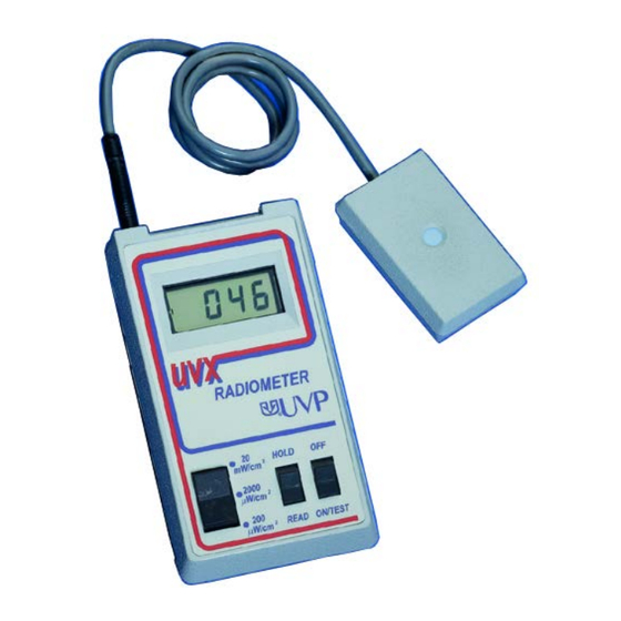
UVP UVX-36
Long Wave Sensor
A l l t r a d e m a r k s , b r a n d n a m e s , a n d b r a n d s a p p e a r i n g h e r e i n a r e t h e p r o p e r t y o f t h e i r r e s p e c t i v e o w n e r s .
• C r i t i c a l a n d e x p e d i t e d s e r v i c e s
• I n s t o c k / R e a d y - t o - s h i p
Artisan Scientific Corporation dba Artisan Technology Group is not an affiliate, representative, or authorized distributor for any manufacturer listed herein.
$
295
.00
In Stock
Qty Available: 1
Used and in Excellent Condition
Open Web Page
https://www.artisantg.com/90125-1
• We b u y y o u r e x c e s s , u n d e r u t i l i z e d , a n d i d l e e q u i p me n t
• F u l l - s e r v i c e , i n d e p e n d e n t r e p a i r c e n t e r
Advertisement
Table of Contents

Related Manuals for Analytik Jena UVP UVX Series


Summary of Contents for Analytik Jena UVP UVX Series
- Page 1 UVP UVX-36 Long Wave Sensor In Stock Qty Available: 1 Used and in Excellent Condition Open Web Page https://www.artisantg.com/90125-1 A l l t r a d e m a r k s , b r a n d n a m e s , a n d b r a n d s a p p e a r i n g h e r e i n a r e t h e p r o p e r t y o f t h e i r r e s p e c t i v e o w n e r s . •...
- Page 2 UVX Radiometer Instruction Guide UVP, LLC Ultra-Violet Products Ltd. 2066 W. 11th Street Unit 1, Trinity Hall Farm Estate Upland, CA 91786 Nuffield Road, Cambridge CB4 1TG UK Phone: (800) 452-6788 Phone: +44(0)1223-420022 Fax: (909) 946-3597 Fax: +44(0)1223-420561 Web Site: www.uvp.com 81-0064-01 Rev M Artisan Technology Group - Quality Instrumentation ...
-
Page 3: Table Of Contents
UVX Radiometer Table of Contents General Instructions ............................5 Introduction ..............................5 Features..............................5 Specifications ............................6 Operating Procedures ..........................6 Radiometer Details ............................9 Circuit Description ............................. 9 Radiometer Circuit Calibration ........................9 Radiometer Maintenance ........................10 Sensor Details ............................. 15 Sensor Characteristics .......................... - Page 4 UVX Radiometer List of Figures Figure 1: Rear and Side Views of Radiometer....................4 Figure 2: Radiometer Functional Block Diagram ..................13 Figure 3: Calibration Current Source ......................14 Figure 4: LCD Display Pin-outs ........................14 Figure 5: UVX-25 Sensor Solarization Curve ..................... 16 Figure 6: Typical UVX-25 Sensor Spectral Response ................
-
Page 5: Figure 1: Rear And Side Views Of Radiometer
UVX Radiometer Figure 1: Rear and Side Views of Radiometer Artisan Technology Group - Quality Instrumentation ... Guaranteed | (888) 88-SOURCE | www.artisantg.com... -
Page 6: General Instructions
UVX Radiometer General Instructions Introduction Your new UVX Digital Radiometer from UVP allows measurement of UV intensities quickly and easily. The digital readout is in radiometric units with a broad dynamic range from 0.1 µW/cm to 20 mW/cm with accuracy and precision traceable to the National Institute of Standards and Technology (NIST). The sensors are cosine corrected for measuring UV radiation at 254, 310 and 365nm. -
Page 7: Specifications
UVX Radiometer • Excellent cosine response with typical curve supplied in the manual • A filter system which significantly reduces shortwave solarization phenomenon • Internal temperature correction retains the accuracy of the sensors at both high and low temperatures • Externally accessible zero adjust •... - Page 8 UVX Radiometer • Place the three position range switch in the 20 mW/cm2 position. Place the READ/HOLD switch in the READ position. • Turn the unit on by placing the OFF-ON/TEST switch in the ON/TEST position. Note: For the first second of operation, the entire display will be turned on demonstrating that all segments, decimal points and “LOBAT”...
- Page 9 UVX Radiometer CAUTION Refer to the Safety Precautions section of this manual before making ultraviolet measurements with this Radiometer. If all the digits are blank except for the leading “1” when the sensor has been placed in the UV radiant incident field, an overrange condition is indicated.
-
Page 10: Radiometer Details
UVX Radiometer Radiometer Details Circuit Description This section describes how the UVX Radiometer operates. Three illustrations are included for use in conjunction with this section. Figure 2 is a Functional Block Diagram. Current to Voltage Converter The silicon detector used in the sensor may be modeled as a current source. For maximum linearity, the detector load should represent a short circuit. -
Page 11: Radiometer Maintenance
UVX Radiometer Procedure Calibration • Remove the battery. Remove the two screws from the bottom of the case and carefully lift off the bottom. As you do this, feed the battery clip through the aperture in the side of the battery holder. Place the bottom of the case aside and lift the PC board out of the case top. - Page 12 UVX Radiometer Troubleshooting Procedures In the event the Radiometer malfunctions, the following procedures will enable the user to determine the source of error and affect repairs. If any of the active circuit elements are replaced in the following procedures, then the calibration procedure must be performed prior to putting the Radiometer back into service.
- Page 13 UVX Radiometer position, then the voltmeter should read less than 5 volts DC. If the voltmeter indicates correctly according to the above requirements and the decimal point fails to come on, then the integrated circuit U2 is malfunctioning and must be replaced. If the voltmeter does not indicate as described above, then the malfunction is in the range selector switch and the UVX must be returned to UVP.
-
Page 14: Figure 2: Radiometer Functional Block Diagram
UVX Radiometer Change the range switch to the 20 uW/cm position. The display should now indicate 0.10 uW/cm2 and the voltmeter should read .0100 volts Again, if the voltmeter indication did not decrease by a factor of 10, then the malfunction is in the range changing switch and the unit must be returned to UVP for repair. -
Page 15: Figure 3: Calibration Current Source
UVX Radiometer Figure 3: Calibration Current Source Figure 4: LCD Display Pin-outs Artisan Technology Group - Quality Instrumentation ... Guaranteed | (888) 88-SOURCE | www.artisantg.com... -
Page 16: Sensor Details
UVX Radiometer Sensor Details Sensor Characteristics Solarization of Filters Shortwave ultraviolet radiation causes a decrease in sensor output that is proportional to total exposure. This is due to changes in the transmission properties of the filters; a phenomenon called solarization. Solarization is especially noticeable in the 254nm sensors. -
Page 17: Figure 5: Uvx-25 Sensor Solarization Curve
UVX Radiometer Figure 5: UVX-25 Sensor Solarization Curve Figure 6: Typical UVX-25 Sensor Spectral Response Artisan Technology Group - Quality Instrumentation ... Guaranteed | (888) 88-SOURCE | www.artisantg.com... -
Page 18: Figure 7: Typical Uvx-31 Sensor Spectral Response
UVX Radiometer Figure 7: Typical UVX-31 Sensor Spectral Response Figure 8: Typical UVX-36 Sensor Spectral Response Artisan Technology Group - Quality Instrumentation ... Guaranteed | (888) 88-SOURCE | www.artisantg.com... -
Page 19: Figure 9: Typical Sensor Response Versus Incidence Angle
UVX Radiometer Figure 9: Typical Sensor Response Versus Incidence Angle Calibration Traceability For direct traceability to NIST standards, UVX sensors must be returned to the UVP calibrations laboratory for calibration once every 6 months. UVP does not stand behind calibrations performed by unauthorized companies. -
Page 20: Sensor Maintenance
UVX Radiometer the actual time that a sensor will remain within tolerance is dependent on such factors as care in handling and total dosage of radiation on the sensor filters (refer to “Solarization of Filters” in this manual). Sensor Maintenance The user should avoid performing corrective maintenance on the sensor. -
Page 21: Figure 10: Schematic Of Uvx Series Sensor
UVX Radiometer Figure 10: Schematic of UVX Series Sensor Figure 1: Measurement of Irradiance Artisan Technology Group - Quality Instrumentation ... Guaranteed | (888) 88-SOURCE | www.artisantg.com... -
Page 22: Figure 12: Typical Output From Low Pressure Mercury Lamp
UVX Radiometer Figure 12: Typical Output From Low Pressure Mercury Lamp Artisan Technology Group - Quality Instrumentation ... Guaranteed | (888) 88-SOURCE | www.artisantg.com... -
Page 23: Application Techniques
UVX Radiometer Application Techniques Definition of Radiant Incidence The UVX Radiometer is an instrument for measuring radiant incidence, where radiant incidence is defined as the power per unit area incident on a surface at a location irradiated by a light source. See Figure 14. Using the metric system of units, radiant incidence is dimensionally given as power per unit area. - Page 24 UVX Radiometer UVP manufactures other sensors which are also calibrated using line sources at other wavelengths. The user must take special precautions when using "line source calibrated sensors" to measure irradiance from lamps radiating at wavelengths other than those for which the sensor was calibrated. A common application of this type occurs when measuring irradiance from phosphor coated lamps which emit continuously over a broad wavelength region.
-
Page 25: Figure 13: Hypothetical Light Source Having An Output At 270Nm Wavelength
UVX Radiometer Figure 13: Hypothetical Light Source Having an Output at 270nm Wavelength Figure 14: Response of Three Sensors Calibrated to Yield the Same Output at 254nm Wavelength Artisan Technology Group - Quality Instrumentation ... Guaranteed | (888) 88-SOURCE | www.artisantg.com... -
Page 26: Cosine Response
UVX Radiometer Figure 15: Continuous Emitter, 285nm Phosphor Coated UV Lamp Cosine Response For a sensor to accurately measure irradiance, it is necessary that it preserve a cosine relationship which depends on the angle of incident radiation. This relationship is a function of the projected area of the sensor, as seen in a plane normal to the incident light. -
Page 27: Safety Precautions
UVX Radiometer Safety Precautions It is essential that adequate precautions be taken in applications using ultra-violet light sources. Prolonged exposures to high intensities can cause painful inflammation of the conjunctiva (the outer membrane of the eye) as well as histological effects in the cornea, iris, and lens of the eye. Reddening or even burning of the skin (erythema), similar to sunburn, will be caused by excessive exposure to ultra- violet energy. -
Page 28: Figure 16: Example, Illustrating Why Sensor Field Of View Is Important When Measuring Irradiance
UVX Radiometer Figure 16: Example, Illustrating Why Sensor Field of View is Important When Measuring Irradiance Figure 17: Projected Area of Sensor Artisan Technology Group - Quality Instrumentation ... Guaranteed | (888) 88-SOURCE | www.artisantg.com... -
Page 29: Figure 18: Cosine Response Of Typical Uvx Sensor (Polar Plot)
UVX Radiometer Figure 18: Cosine Response of Typical UVX Sensor (Polar Plot) Artisan Technology Group - Quality Instrumentation ... Guaranteed | (888) 88-SOURCE | www.artisantg.com... -
Page 30: Component List, Replacement Parts, And Options
UVX Radiometer Component List, Replacement Parts, and Options Component List The following list is the components used on the printed circuit board assembly P/N 57-0005-04. PART NO. DESCRIPTION COMPONENT DESIGNATION 57-0005-01 Printed Circuit Board, UVX Radiometer 57-0041-10 Resistor, 4.99K, 1/8W, 1% 50-0041-21 Resistor, 536 ohms, 1/8W, 1% 50-0041-22... -
Page 31: Replacement Parts
UVX Radiometer In addition to the components listed above, the UVX that includes the Recorder Output Option (57-0005- 05) also has the following components. PART NO. DESCRIPTION COMPONENT DESIGNATION 52-0004-06 Capacitor, .1 µ, f, 12V, 20% (C14) 55-0063-01 Phone Jack, Enclosed, Subminiature (J2) 51-0029-01 Integrated Circuit, OP97... -
Page 32: Warranty
UVX Radiometer Warranty UVP's quality instruments are guaranteed to be free of defects in materials, workmanship, and manufacture for one (1) year from date of purchase. Consumable and disposable products, including, but not limited to lamps or light tubes, filters, or rechargeable batteries, are guaranteed to be free from detects in manufacture and materials for ninety (90) days from date of purchase.
Need help?
Do you have a question about the UVP UVX Series and is the answer not in the manual?
Questions and answers