
Related Manuals for SolaX Power X1-Micro 750 W


Summary of Contents for SolaX Power X1-Micro 750 W
- Page 1 X1-Micro 2 in 1 750 W / 800 W / 900 W / 1000 W / 1200 W Installation Manual Version 7.0 www.solaxpower.com eManual in the QR code or at http://kb.solaxpower.com/...
- Page 2 Safety 1. Contents may be periodically updated or revised. SolaX reserves the right to make improvements or changes in the product(s) and the program(s) described in this manual without the prior notice. 2. The installation, maintenance and grid-related setting can only be performed by qualified personnel who: •...
- Page 3 WARNING! Risk of personnel injury or inverter damage • During operation, do not touch any parts including the enclosure lid of the inverter. • Never connect or disconnect the AC or DC connectors when the microinverter is running. • Make sure that the input DC voltage ≤ Maximum DC input voltage of the inverter. Overvoltage may cause permanent damage to the inverter, which is NOT covered by the warranty.
- Page 4 Packing List Including in the box: Microinverter Installation Map Make sure N for North Panel type: Customer information: Gateway series number: Azimuth: Tilt: Sheet_of_ COLUMN Installation map × 1 Inverter × 1 Documents Sold separately: AC trunk port disconnect 1.2m/2m/2.4m AC trunk AC trunk end cap AC trunk connector tool...
- Page 5 NOTICE! • For outdoor-installation, precautions against direct-sunlight, rain -exposure and snow-accumulation are-recommended. • Exposure to direct sunlight raises the temperature inside the device. This temperature rise poses no safety risks,but-may impact the device performance. Installation Angle Parallel to the rail Installation Tools Cable tie Multimeter...
- Page 6 Additionally Required Materials Required Material Requirements Current: 50A for 10 AWG/40 A for 12 AWG (If there are additional safety AC circuit breaker regulations, please refer to the local safety regulations) Guide rail According to actual needs Sliding block Matching with the guide rail Screw Matching with the guide rail AC cable...
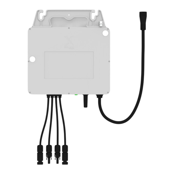
- Page 7 Maximum over X1-Micro 1000 X1-Micro 1200 current protection device 6@220V 5@220V Maximum number 6@230V 5@230V 50 A per 10AWG branch 6@240V 5@240V Appearance and Dimensions 260 mm 40 mm Terminal Description...
- Page 8 Item Description Decisive voltage class Spare ground For standby earth connection. cable clip PV terminal For PV connection. DVC-C Indicator Show the status of the device. Antenna To receive and transmit WiFi signal. AC terminal For AC connection. DVC-C A connection component for electrical Earth lug devices which need grounding (perferred grounding method).
- Page 9 NOTICE! • In order to better fix the AC cable, it is recommended to use more cable ties to band the AC cable. • Choose the cable tie according to the rail width and the length of self-purchased accessories. AC trunk cable Female Male Male...
- Page 10 NOTICE! • When connecting AC cables in the middle, please follow the diagram below. Female Male Female Male Insert Insert Click X X X X X X X X X X X X X X X X X X X X X X X X X X X X X X X X paste NOTICE! •...
- Page 11 Method 1 (major connection method): Let the earth lug touch the rail Method 2: Strip 1.2 ± 0.1 N·m NOTICE! • Step 10 and 11 should be finished by at least 2 or 3 trained and experienced workers. • If the pannels are too far from the microinverter, please use extended DC cable for connection.
- Page 12 NOTICE! • After finish the installation, please fix the PV panels. Ground Connect L, N and PE AC end cable-M cable to the distribution box accordingly NOTICE! • The length of AC end cable shall depends on the actual installation scene. NOTICE! •...
- Page 13 Ground Connect L, N and PE AC end cable-M cable to the distribution box accordingly NOTICE! • Please check the connection stability between pin contacts with cable and connector using a pull force not exceeding 300N after crimping pin contacts and inserting the pin contacts with cable to the connector.
- Page 14 Power on the System Step 1: First turn on the AC breaker on the branch circuit and then the main AC breaker of the house. Step 2: Wait for about 2 minutes until the system is initiated. <2.4 m AC junction box Red-L Black-N Green/Yellow-PE...
- Page 15 Step 2: Run the App, select the language, and touch [Sign up] at the bottom of Monitoring App. Step 3: Create the account. Log in the App after registration finished. xxxxxxxxxx xxxxxxxxxx...
- Page 16 Step 4: Create a site by filling in the site information. Step 5: Click [Microinverter], scan the QR code of microinverter to bind the device. XXXXXXXXXXX NOTICE • If scanning the QR code step fails,.then try to scan the one dimensional code. Scanning one dimensional code may lead to inaccurate scan results).
- Page 17 Step 6: Enter your WiFi account and password. Then, connect the device hotspot (name: Wifi_XXXXXXXXXX), start to configure the device network. XXXXXXXXXXXXX XXXXXXXXXXXXX XXXXXXXXXXXXX XXXXXXXXXXXXX NOTICE! • Before Network configuration, make sure the DC or AC side of the microinverter has been energized and the dongle moudle has been connected to "Upgrade/Dongle"...
- Page 18 Step 8: Click [Layout] to customize your device layout and save the settings. Step 9: Click the site to view your device detail information.
- Page 19 Technical Data • DC Input Model X1-Micro 750 X1-Micro 800 X1-Micro 900 X1-Micro 1000 X1-Micro 1200 Max. recommended DC 240 to 470+ 320-540+ 360-600+ 400-670+ 400-670+ power [W] Max. PV voltage [d.c. V] MPPT voltage range 22-60 [d.c. V] Nominal input voltage [d.c.
- Page 20 *2 Refer to local rules and regulations for the specific number of microinverters per branch. • Efficiency, Safety and Protection Model X1-Micro 750 X1-Micro 800 X1-Micro 900 X1-Micro 1000 X1-Micro 1200 MPPT efficiency 99.9% Maximum efficiency 96.5% Security & Protection Safety IEC62109, IEC63027 IEC 61000, EN 62920, EN 301489, EN 55011...
- Page 21 Contact Information AUSTRALIA UNITED KINGDOM Unit C-D Riversdale House, Riversdale 21 Nicholas Dr, Dandenong South VIC 3175 Road, Atherstone, CV9 1FA +61 1300 476 529 +44 (0) 2476 586 998 service@solaxpower.com.au service.uk@solaxpower.com TURKEY GERMANY Am Tullnaupark 8, 90402 Nürnberg, Fevzi Çakmak mah. aslım cd. no 88 A Germany Karatay / Konya / Türkiye service.tr@solaxpower.com...
- Page 22 Warranty Registration Form For Customer (Compulsory) Name Country Phone Number Email Address State Zip Code Product Serial Number Date of Commissioning Installation Company Name Installer Name Electrician License No. For Installer Module ( If Any ) Module Brand Module Size(W) Number of String Number of Panel Per String Battery ( If Any )
- Page 23 Add: Unit C-D Riversdale House, Riversdale Road, Atherstone, CV9 1FA Tel: +44 (0) 2476 586 998 E-mail: service.uk@solaxpower.com Authorised Representative (AUS) Name: SolaX Power AUS Pty Ltd Add: 21 Nicholas Dr, Dandenong South VIC 3175 Tel: +61 1300 476 529 E-mail: service@solaxpower.com.au...
- Page 24 SolaX Power Network Technology (Zhejiang) Co., Ltd. ADD.: No. 278, Shizhu Road, Chengnan Sub-district, Tonglu County, Hangzhou, Zhejiang, China E-mail: info@solaxpower.com 320102083407 Copyright © SolaX Power Network Technology (Zhejiang) Co., Ltd. All rights reserved.
Need help?
Do you have a question about the X1-Micro 750 W and is the answer not in the manual?
Questions and answers