
Subscribe to Our Youtube Channel
Related Manuals for SolaX Power X1-Micro 4 in 1


Summary of Contents for SolaX Power X1-Micro 4 in 1
- Page 1 X1-Micro 4 in 1 1300 W / 1500 W / 1600 W / 1800 W / 2000 W / 2200 W User Manual Version 0.0 www.solaxpower.com eManual in the QR code or at http://kb.solaxpower.com/...
- Page 3 STATEMENT Copyright Copyright © SolaX Power Network Technology (Zhejiang) Co., Ltd. All rights reserved. No part of this manual may be reproduced, transmitted, transcribed, stored in a retrieval system, or translated into any language or computer language, in any form or by any means without the prior written permission of SolaX Power Network Technology (Zhejiang) Co., Ltd.
- Page 4 About This Manual Scope of Validity This manual is an integral part of X1-Micro 4 in 1 Series. It describes the installation, electrical connection, commissioning, maintenance and troubleshooting of the product. Please read it carefully before operating. X1-Micro 1300 X1-Micro 1500...
- Page 5 Conventions The symbols that may be found in this manual are defined as follows. Symbol Description Indicates a hazardous situation which, if not avoided, DANGER will result in death or serious injury. Indicates a hazardous situation which, if not avoided, WARNING could result in death or serious injury.
-
Page 6: Table Of Contents
Table of Contents Safety ......................1 1.1 General Safety ........................1 1.2 Safety Instructions of PV, Inverter and Grid ...............1 1.2.1 Safety Instructions of PV ..................2 1.2.2 Safety Instructions of Microinverter ..............2 1.2.3 Safety Instructions of Utility Grid ..............4 1.2.4 Inverter backfeed current onto the array ............4 1.2.5 Safety Instructions of AC trunk cable .............4 Product Overview ..................5... - Page 7 5.2 Troubleshooting .........................30 5.3 On-Site Inspection (for qualified installer only) ............32 5.4 Maintenance ........................33 5.4.1 Maintenance routines ..................33 5.4.2 Upgrading Firmware ....................34 Decommissioning ..................36 6.1 Disassembling the Microinverter .................36 6.2 Packing the Microinverter ....................36 6.3 Transportation and Storage ....................37 6.4 Disposal of the Microinverter ..................37 Technical Data ..................38 Appendix ....................42 8.1 INSTALLATION MAP ......................42...
-
Page 9: Safety
Safety General Safety The series inverter has been meticulously designed and thoroughly tested to comply with the relevant state and international safety standards. Nevertheless, like all electrical and electronic equipment, safety precautions must be observed and followed during the installation of the inverter to minimize the risk of personal injury and ensure a safe installation. -
Page 10: Safety Instructions Of Pv
Safety 1.2.1 Safety Instructions of PV DANGER! Lethal danger from electric shock due to the PV! • Never touch the positive or negative pole of PV connecting device. Touching both of them at the same time is prohibited as well. •... - Page 11 Safety WARNING! • The installation place should be away from humid or corrosive substance. Avoid installation near extremely hot/cold environment. • Please consult the manufacutuer for non-standard installation conditions. • Make sure that the microinverter is installed under the PV module in case of direct exposure to UV, rain and other harmful weather events.
-
Page 12: Safety Instructions Of Utility Grid
Safety 1.2.3 Safety Instructions of Utility Grid NOTICE! • Only with permissions of local utility grid company, the microinverter can be connected to the grid. • The installer must provide Over Current Protection Devices (OCPD) and external disconnect switches. 1.2.4 Inverter backfeed current onto the array NOTICE! This requirement protects against overloading of array wiring due to backfeed currents... -
Page 13: Product Overview
Figure 2-1 System overview diagram X1-Micro 4 in 1 series The X1-Micro 4 in 1 series manages system energy. Microinverters convert the direct current power generated from the PV modules into grid-compatible AC current. They send their operation data and the output information of PV modules to the monitoring platform, including PV voltage, current, power, etc., which is... - Page 14 Product Overview Tracking (MPPT). The X1-Micro 4 in 1 is integrated with MPPT, which means that even though a PV module runs abnormally or is shaded, other modules won't be affected and can operate the unshaded string at maximum efficiency point. This function plays an important role to improve the efficiency of a photovoltaic (PV) generation system.
-
Page 15: Highlights
Product Overview Highlights • Max output power up to 2200VA with four independent input channels(MPPT) • Up to 20A DC input current to be compatible with the high power PV module • Built-in industrial grade Wi-Fi module for high reliability •... -
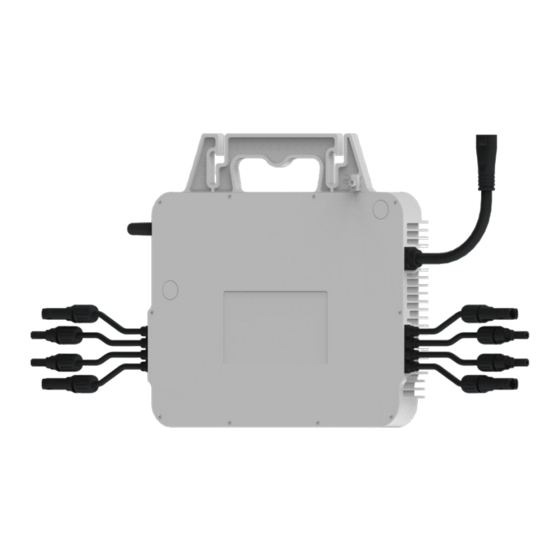
Page 16: Terminals Of Microinverter
Product Overview 2.3.3 Terminals of Microinverter Figure 2-4 Terminals of Microinverter Table 2-1 Description of terminals Item Description Spare ground For standby earth connection. cable clip PV terminal For PV connection. Indicator Show the status of the device. Antenna To receive and transmit WiFi signal. AC terminal For AC connection. - Page 17 Product Overview Symbol Description Refer to the operating instructions. The microinverter can not be disposed together with the household waste. Disposal information can be found in the enclosed documentation. ANATEL certification.
-
Page 18: Preparation Before Installation
Preparation before Installation Unpacking and Inspection 3.1.1 Unpacking • The microinverter undergoes 100% testing and inspection before shipping from the manufacturing facility. However, transport damage may still occur. Before unpacking the Microinverter , please verify that the model and outer packing materials for damage, such as holes and cracks. -
Page 19: Packing Lists
Preparation before Installation Packing Lists Including in the box: Microinverter Installation Map Make sure N for North Panel type: Customer information: Gateway series number: Azimuth: Tilt: Sheet_of_ COLUMN Male pin contact × 3 Installation map × 1 Male connector × 1 Inverter ×... -
Page 20: Installation Angel Requirement
Preparation before Installation • Do not install the microinverter in areas with flammable, explosive and corrosive materials; • Do not install the microinverter in areas near combustibles and antennas; • Install all microinverters and DC connectors under the PV modules. •... -
Page 21: Tools Requirement
Preparation before Installation Tools Requirement 3.4.1 Recommended Equipment Installation tools include but are not limited to the following recommended ones. If necessary, use other auxiliary tools on site. Cable tie Multimeter Measuring tape Utility knife Torque screwdriver Marker (Phillips head: M4) Diagonal pliers Allen key Crimping tool for PV... - Page 22 Preparation before Installation Maximum over X1-Micro 1300 X1-Micro 1500 current protection device 6@220V 5@220V Maximum number 7@230V 6@230V 50 A per 10AWG branch 7@240V 6@240V 5@220V 4@220V Maximum number 5@230V 4@230V 40 A per 12AWG branch 5@240V 5@240V Maximum over X1-Micro 1600 X1-Micro 1800 current protection...
-
Page 23: Installation
Installation Accessories Description 1.2m/2m/2.4m AC trunk cable DC extension cable (if necessary) AC trunk connector AC trunk end cap AC trunk port disconnect tool Female connector Male connector NOTICE! • The above accessories are not included in the package and need to be purchased separately. -
Page 24: Microinverter Installation
Installation Microinverter Installation WARNING! • Avoiding pulling or holding the AC cable with your hand directly. Hold the handle of the microinverter instead. WARNING! • Pay attention to the earth lug. Risk of hand injury! - Page 25 Installation Step 1: Rail Installation A) The installer has to install the rails on the roof and fix them with screws to ensure a stable installation environment for microinverters. Step 2: Plan the Number and Installation Location of Microinverters A) Arrange the installation number and location of each microinverter according to the layout of the photovoltaic system.
- Page 26 Installation Step 4: Build the AC trunk cable A) Dissemble the Male connector into four parts: part I, part II, part III and part IV. B) Strip the AC trunk cable (about 40 mm) and then strip L, N and PE cable (about 9 mm) inside the AC trunk cable.
- Page 27 Installation NOTICE! • Choose the cable tie according to the rail width and the length of self-purchased accessories. • Avoid placing AC connectors nearby any drainage channels. • AC trunk connectors should be placed nearby the AC cable of microinverters. •...
- Page 28 Installation B ) Plug the male terminal of AC trunk cable into the female terminal of AC trunk connector. AC trunk cable Female Male NOTICE! • In order to better fix the AC trunk cable, it is recommended to use more cable ties to band the AC trunk cable.
- Page 29 Installation E) Cover vacant AC ports with AC trunk end cap. Male Step 6: AC Trunk Cable Connection A) Plug the AC connector of the microinverter into the trunk cable connector. The connection is completed when you hear a "click". NOTICE! •...
- Page 30 Installation Step 7: Complete the Installation Map A) Remove the serial number label on the machine and attach to the installation map following the planed installation place. X X X X X X X X X X X X X X X X X X X X X X X X X X X X X X X X paste Step 8: Grounding methods...
- Page 31 Installation Method 2: Strip the PE cable, place the PE cable on the rail and fix it with screws. 1.2 ± 0.1 N·m Step 9: Connect Multiple PV Modules to Microinverter NOTICE! • At least two or three trained and experienced workers are required to finish this step. WARNING! •...
-
Page 32: Microinverter System Initiating
Installation NOTICE! • If the pannels are too far from the microinverter, please use DC extension cables for connection. B) Cover the PV modules above the microinverters and fix the PV panels. C) Then connect it to the local grid. Microinverter System Initiating 4.3.1 Initiate the System... -
Page 33: Setup Monitoring System
Installation Step 1: First turn on the AC breaker on the branch circuit and then the main AC breaker of the house. Step 2: Wait for about 2 minutes until the system is initiated. 4.3.2 Setup Monitoring System Downloading and installing App Select and scan the QR code below to download SolaxCloud APP. - Page 34 Installation Choose your identity as [Distributor/Installer] or [End User]. Fill in your registration Email, input the Verification code, and enter your password to create the account. Log in the App after registration finished. xxxxxxxxxx xxxxxxxxxx NOTICE! • App registration via Sign up is for end-users. If you want to apply for an account of agent, please send an email to: service@solaxpower.com.
- Page 35 Installation Network Configuration NOTICE! • Before Network configuration, make sure the DC or AC side of the microinverter has been energized and the dongle moudle has been connected to "Upgrade/Dongle" port of the Microinverter . Click [Microinverter], scan the QR code of microinverter to bind the device. XXXXXXXXXXX NOTICE •...
- Page 36 Installation Wait for a while, the microinverter will configurate network automatically. After configuration succeeds, please remember to change to your home WiFi for the following operations. XXXXXXXXXXX XXXXXXXXXXX Click [Layout] to customize your device layout and save the settings.
- Page 37 Installation Click the site to view your device detail information.
-
Page 38: Troubleshooting And Maintenance
Troubleshooting and Maintenance LED Indicator Status LED Indicator Status Description Microinverter startup. If the light flashes once in 1s, flashes in 10s or still flashes Yellow light flash after 10s, microinverter startup fails or DSP firmware is upgrading. Yellow light steady on Microinverter standby/self-checking. - Page 39 Troubleshooting and Maintenance Code Faults Diagnosis and solutions Grid Voltage Out of Range. -Check if the mains cable is loose. IE0003 GridVoltFault -Wait for a while and the system will reconnect when the utility is back to normal. -Or seek help from us. Grid Frequency Out of Range.
-
Page 40: On-Site Inspection (For Qualified Installer Only)
Troubleshooting and Maintenance Code Faults Diagnosis and solutions PV Direction Fault. IE0030 PvConnDirFault -Check if the PV+/- sides are connected correctly. -Or seek help from us. Relay Fault. -Check the grid connection. IE0031 GridRelayFault -Restart the inverter. -Or seek help from us. PowerTypeFault: -Check the version of Module and DSP. -
Page 41: Maintenance
Troubleshooting and Maintenance Maintenance Regular maintenance is required for the Microinverter. The table of “Proposal of Maintenance” below lists the operational maintenance for expressing the optimum device performance. More frequent maintenance service is needed in the worse work environment. Please make records of the maintenance. WARNING! •... -
Page 42: Upgrading Firmware
Troubleshooting and Maintenance 5.4.2 Upgrading Firmware Upgrade precautions WARNING! • If the DSP and Integrated WiFi Module firmware need to be upgraded, please note that WiFi Module firmware firmware must be upgraded first, then DSP firmware! • Please make sure that the category format is correct, do not modify the firmware file name. - Page 43 Troubleshooting and Maintenance Select Remote Upgrade, choose the microinverter you want to upgrade and click the upgrade icon. If you need batch upgrade, please select Equipment Classification, Applicable Model and Update program first. Then choose the models you want to upgrade, and click Batch Upgrade.
-
Page 44: Decommissioning
Decommissioning Disassembling the Microinverter To disassembling the microinverter » De-energize the AC breaker. » Dismount the PV module from the guide rail for meter detection. » Use a meter to check the DC cables and make sure no current flow exists in the wires between microinverter and module. -
Page 45: Transportation And Storage
Decommissioning Transportation and Storage If the microinverter is not put into use immediately, the transportation and storage requirements needs to be met: Transportation • Observe the caution signs on the packaging of microinverter before transportation. • Wear protective gloves when carrying the equipment by hand to prevent injuries. Storage •... -
Page 46: Technical Data
Technical Data • DC Input Model X1-Micro 1300 X1-Micro 1500 X1-Micro 1600 Max. recommended DC power [W] 300 to 505+ 320 to 540+ 360 to 600+ Max. PV voltage [d.c. V] MPPT voltage range [d.c. V] 22-60 Max. PV current [d.c. A] 4 ×... - Page 47 Technical Data Model X1-Micro 1300 X1-Micro 1500 X1-Micro 1600 5.91@220V 6.82@220V 7.28@220V Maximum continuous output 5.66@230V 6.53@230V 6.96@230V current [A] 5.42@240V 6.25@240V 6.67@240V Power factor range >0.99(-0.8~0.8 adjustable) 6@220V 5@220V 5@220V Maximum units per 10 AWG 7@230V 6@230V 5@230V branch² 7@240V 6@240V 6@240V...
- Page 48 Technical Data Note: *1 Norminal AC voltage/frequency range may vary according to local rules and regulations. *2 Refer to local rules and regulations for the specific number of microinverters per branch. • Efficiency, Standard and Environment Limit Model X1-Micro 1300 X1-Micro 1500 X1-Micro 1600 Efficiency...
- Page 49 Technical Data • Generic Data Model X1-Micro 1300 X1-Micro 1500 X1-Micro 1600 Dimensions (W/H/D)[mm] 322 × 242 (302) × 48.5 Net weight [kg] Heat dissipation treatment Natural convection Monitoring³ SolaXCloud Communication interface Built-in Wi-Fi Model X1-Micro 1800 X1-Micro 2000 X1-Micro 2200 Dimensions (W/H/D)[mm] 322 ×...
-
Page 50: Appendix
Appendix INSTALLATION MAP... -
Page 51: Wiring Diagram - 230Vac Single Phase
Appendix WIRING DIAGRAM – 230VAC SINGLE PHASE... -
Page 52: Wiring Diagram - 230Vac Three Phase
Appendix WIRING DIAGRAM – 230VAC THREE PHASE... - Page 53 Contact Information UNITED KINGDOM AUSTRALIA Unit C-D Riversdale House, Riversdale 21 Nicholas Dr, Dandenong South VIC 3175 Road, Atherstone, CV9 1FA +61 1300 476 529 +44 (0) 2476 586 998 service@solaxpower.com service.uk@solaxpower.com TURKEY GERMANY Fevzi Çakmak mah. aslım cd. no 88 A Am Tullnaupark 8, 90402 Nürnberg, Karatay / Konya / Türkiye Germany...
- Page 55 Warranty Registration Form For Customer (Compulsory) Name Country Phone Number Email Address State Zip Code Product Serial Number Date of Commissioning Installation Company Name Installer Name Electrician License No. For Installer Module ( If Any ) Module Brand Module Size(W) Number of String Number of Panel Per String Battery ( If Any )
- Page 56 EU member states. Safe distance warning Use the X1-Micro 4 in 1 in the environment with the temperature between -40°C and 65°C, The device complies with RF specifications when the device used at 20cm from your body.
- Page 57 Add: Unit C-D Riversdale House, Riversdale Road, Atherstone, CV9 1FA Tel: +44 (0) 2476 586 998 E-mail: service.uk@solaxpower.com Authorised Representative (AUS) Name: SolaX Power AUS Pty Ltd Add: 21 Nicholas Dr, Dandenong South VIC 3175 Tel: +61 1300 476 529 E-mail: service@solaxpower.com...
- Page 58 SolaX Power Network Technology (Zhejiang) Co., Ltd. Add.: No.278, Shizhu Road, Chengnan Sub-district, Tonglu County, Hangzhou, Zhejiang, China E-mail: info@solaxpower.com 320101100100 Copyright © SolaX Power Network Technology (Zhejiang) Co., Ltd. All rights reserved.
Need help?
Do you have a question about the X1-Micro 4 in 1 and is the answer not in the manual?
Questions and answers