Table of Contents
Advertisement
Quick Links
Advertisement
Table of Contents

Subscribe to Our Youtube Channel
Related Manuals for TLV S-COS-16


Summary of Contents for TLV S-COS-16
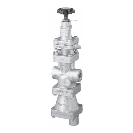
- Page 1 ISO 9001 ISO14001 Manufacturer Kakogawa, Japan is approved by LRQA Ltd. to ISO 9001/14001 Instruction Manual Pressure Reducing Valve for Steam Featured Models: S-COS-16/S-COSR-16 172-65260M-09 Publication date 25 July 2023 Copyright © 2023 TLV CO., LTD.
-
Page 2: Table Of Contents
Specifications ........................... 6 Acceptable Operating Range ....................7 Correct usage of the product ....................8 Configuration .......................... 11 Installation ..........................12 Adjustment ..........................15 Maintenance ........................... 16 Disassembly ........................... 17 Troubleshooting ........................23 TLV EXPRESS LIMITED WARRANTY ................... 26 Service ........................... 28... -
Page 3: Introduction
The TLV S-COS, with a built-in separator and steam trap, eliminates these problems and makes possible the supply of very dry steam at a constant pressure. Both the TLV S-COS and S-COSR provide a more stable secondary pressure than conventional pressure reducing valves. -
Page 4: Safety Considerations
• The three types of cautionary items above are very important for safety: be sure to observe all of them as they relate to installation, use, maintenance and repair. Furthermore, TLV accepts no responsibility for any accidents or damage occurring as a result of failure to observe these precautions. - Page 5 Caution Be sure to use only the recommended components when repairing the product, and NEVER attempt to modify the product in any way. Failure to observe these precautions may result in damage to the product and burns or other injury due to malfunction or the discharge of fluids. Caution Do not use excessive force when connecting threaded pipes to the product.
-
Page 6: Specifications
Specifications Caution Install properly and DO NOT use this product outside the recommended operating pressure, temperature and other specification ranges. Improper use may result in such hazards as damage to the product or malfunctions that may lead to serious accidents. Local regulations may restrict the use of this product to below the conditions quoted. -
Page 7: Acceptable Operating Range
Acceptable Operating Range Model S-COS-16, S-COSR-16 Primary pressure range 0.2 to 1.6 MPaG Adjustable pressure range (all conditions must Within 10 to 84% of the primary pressure be met) Minimum adjustable pressure of 0.03 MPaG Pressure differential between 0.07 to 0.8 MPa... -
Page 8: Correct Usage Of The Product
Correct usage of the product Caution Install properly and DO NOT use this product outside the recommended operating pressure, temperature and other specification ranges. Improper use may result in such hazards as damage to the product or malfunctions that may lead to serious accidents. Local regulations may restrict the use of this product to below the conditions quoted. - Page 9 Recommended straight pipe runs If the product is installed either directly before or after an elbow or control valve, unevenness in flow may result in chattering and unstable pressure. To ensure stable steam flow, it is recommended that the product be installed on straight runs of piping, as illustrated below. (d = pipe diameter) 1.
- Page 10 • Maintain a straight piping run of 30 d or more (L) when a control valve or an automated valve (on-off valve) is installed. (Example: if nominal size is 25 mm, have 750 mm or more)
-
Page 11: Configuration
Configuration S-COS-16 S-COSR-16 ⑱ ⑰ ⑲ ⑳ ⑮ ⑯ ⑯ ⑭ ⑱ ⑰ ⑬ ⑨ ⑪ ⑭ ⑩ ⑮ ⑫ ⑲ ⑫ ⑬ ⑪ ⑧ ⑨ ⑦ ⑩ ⑥ ⑧ ④ ④... -
Page 12: Installation
Installation Caution Install properly and DO NOT use this product outside the recommended operating pressure, temperature and other specification ranges. Improper use may result in such hazards as damage to the product or malfunctions that may lead to serious accidents. Local regulations may restrict the use of this product to below the conditions quoted. - Page 13 4. Piping support Install the product, paying attention to avoid excessive load, bending and vibration. Support the inlet and outlet pipes securely. S-COS S-COSR 5. Maintenance space Leave sufficient space for maintenance, inspection and repair. 6. Trap outlet pipe For ease of maintenance, installation of a union connection is recommended for the trap outlet pipe.
- Page 14 between the product and the steam-using equipment is great, a possible drop in pressure should be taken into consideration when selecting the piping size. In addition, when installing the strainer, the strainer screen should be either at the 3 o’clock or 9 o’clock position to prevent condensate accumulation. Diffuser Straight piping (d = pipe diameter) 10 d or longer upstream...
-
Page 15: Adjustment
Adjustment The product should be properly adjusted for protection of the steam-using equipment against water hammer. It is necessary to blow down all pipe lines thoroughly. The blowdown is especially important if the line is new or has been shut down for a long period of time. Take particular care to ensure that matter such as condensate and dirt does not remain inside the steam-using equipment. -
Page 16: Maintenance
Maintenance Caution Take measures to prevent people from coming into direct contact with product outlets. Failure to do so may result in burns or other injury from the discharge of fluids. Be sure to use only the recommended components when repairing the product, and NEVER attempt to modify the product in any way. -
Page 17: Disassembly
Disassembly Warning NEVER apply direct heat to the float. The float may explode due to increased internal pressure, causing accidents leading to serious injury or damage to property and equipment. Caution When disassembling or removing the product, wait until the internal pressure equals atmospheric pressure and the surface of the product has cooled to room temperature. - Page 18 Disassembling the pilot section The diaphragm is removed by using the notch in the pilot body. Loosen and remove the pilot valve seat with a box wrench. Lift the pilot valve spring up and out with a pair of tweezers. Then loosen and remove the screen holder to remove the pilot screen.
- Page 19 Disassembling the separator and main valve section Turn the product upside down for easy dismantling of the separator and main valve. Loosen the hex bolts and remove the trap body. Be careful, as the separator may drop off when the product is returned to the normal attitude.
- Page 20 Disassembling the main valve and cover plug/cover section Turn the product upside down for easy dismantling of the main valve. Loosen and remove the cover plug. Removal of the cover plug and pressed-in sleeve permits the removal of the main valve, main valve spring and the screen. Loosen the main valve seat with a box wrench and remove it from the main body.
- Page 21 Cleaning After inspection and removal of any abnormality, clean and reassemble the parts. The following parts will require cleaning before reassembly: Trap cover (S-COS), cover plug (S-COSR), adjustment screw, pilot valve, pilot valve seat, main valve, main valve seat, pilot screen, pilot valve stem, piston, separator screen (S-COS), screen (S-COSR), piston ring, cylinder, float (S-COS), trap valve seat (S-COS) It is permissible to clean using water, however cleaning with a mild detergent is recommended for more effective cleaning.
- Page 22 Reassembly Assemble the unit using the same procedure as used for disassembling it; but in reverse order. Observe the following precautions: The PTFE gaskets may be re-used if free from fault, crushing or deformation. Apply anti-seize to the threaded portion of screws and bolts, the spring retainer, ball and adjustment screw.
-
Page 23: Troubleshooting
Troubleshooting Warning NEVER apply direct heat to the float. The float may explode due to increased internal pressure, causing accidents leading to serious injury or damage to property and equipment. Caution When disassembling or removing the product, wait until the internal pressure equals atmospheric pressure and the surface of the product has cooled to room temperature. - Page 24 Problem Symptom Cause Remedy The product body is not No steam is being Check the valves and secondary warm supplied or the inlet valve piping pressure is closed does not rise The body is warm, but The entrance to the Clean or blow down the pressure does not screens or strainer is...
- Page 25 Problem Symptom Cause Remedy Hunting or Occurs at low steam It is being operated below Check the volume of chattering demand the lower flow rate limit steam supply, replace with occurs a smaller diameter valve Hunting never stops There is too high a Use a two-stage reduction reduction ratio (operated arrangement...
-
Page 26: Tlv Express Limited Warranty
TLV; or 4. disasters or forces of nature or Acts of God; or 5. abuse, abnormal use, accidents or any other cause beyond the control of TLV, TII or TLV group companies; or 6. improper storage, maintenance or repair; or 7. - Page 27 HEREBY, INCLUDING THE IMPLIED WARRANTIES OF MERCHANTABILITY AND FITNESS FOR A PARTICULAR PURPOSE, DO NOT COVER, AND NEITHER TLV, TII NOR ITS TLV GROUP COMPANIES WILL IN ANY EVENT BE LIABLE FOR, INCIDENTAL OR CONSEQUENTIAL DAMAGES, INCLUDING, BUT NOT LIMITED TO LOST PROFITS, THE COST OF DISASSEMBLY AND SHIPMENT OF THE DEFECTIVE PRODUCT, INJURY TO OTHER PROPERTY, DAMAGE TO BUYER’S OR THE FIRST...
-
Page 28: Service
Service For Service or Technical Assistance: Contact your TLV representative or your regional TLV office. In Europe: Tel: [49]-(0)7263-9150-0 Fax: [49]-(0)7263-9150-50 Daimler-Benz-Straße 16-18, 74915 Waibstadt, Germany Tel: [44]-(0)1242-227223 Fax: [44]-(0)1242-223077 Units 7 & 8, Furlong Business Park, Bishops Cleeve, Gloucestershire GL52 8TW, U.K.
Need help?
Do you have a question about the S-COS-16 and is the answer not in the manual?
Questions and answers