Tigo TS4-F Troubleshooting Manual
Hide thumbs
Also See for TS4-F:
- Installation manual (31 pages) ,
- Installation & quick start manual (9 pages) ,
- Installation manual (22 pages)
Advertisement
Quick Links
Advertisement

Subscribe to Our Youtube Channel
Related Manuals for Tigo TS4-F


Summary of Contents for Tigo TS4-F
- Page 1 Troubleshooting Guide TS4-F, TS4-R-F, TS4-A-F, TS4-A-2F and RSS Transmitter...
- Page 2 National Electric Code (NEC) ANSI/NFPA 70 and/or local electrical codes. When the photovoltaic array is exposed to light, it supplies a DC voltage to the Tigo TS4 units and the output voltage may be as high as the PV module open circuit voltage (V ) when connected to the module.
- Page 3 • Never apply an external voltage source to a module or string equipped with TS4-F, TS4-R-F, or TS4-A-F/TS4-A-2F units. • If parallel string connections are needed, first connect the TS4-F, TS4-R-F, or TS4-A-F to the PV modules, then connect all TS4-F, TS4-R-F, or TS4-A-F outputs in series, and finally pass one side (+ or -) of the homeruns through the PLC transmitter to turn the system ON.
- Page 4 TABLE OF CONTENTS TS4-F Rapid Shutdown System System Overview: TS4-F System Overview: TS4-A-F System Overview: TS4-A-2F Testing Rapid Shutdown Troubleshooting Basics Troubleshooting - String-level Troubleshooting - Module-level Troubleshooting - Module-level Troubleshooting - Module-level Troubleshooting - System-level Troubleshooting - RSS Transmitter...
- Page 5 Tigo’s TS4-F (or TS4-A-F, TS4-A-2F) and RSS Transmitter are a UL-certified PVRSS (Photovoltaic Rapid Shutdown System) when installed together. The RSS Transmitter supplies a keep-alive signal along one of the DC homeruns and the TS4-F units on each module will shut down when the Transmitter is switched off.
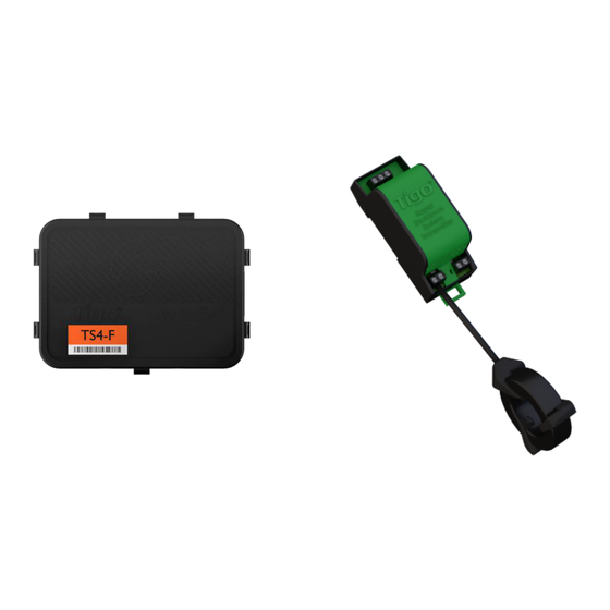
- Page 6 The TS4-F requires a Tigo RSS Transmitter or inverter with built-in transmitter for operation. The Tigo RSS Transmitter is installed in line with a solar PV inverter, as shown, and can be installed inside the inverter or external to it.
- Page 7 3. Inverter Note: connect modules to TS4-A inputs before connecting outputs The TS4-A-F requires a Tigo RSS Transmitter or inverter with built-in transmitter for operation. • TS4-A-F mounting is recommended on the upper right as shown, but can be placed elsewhere on the frame or bolted to the racking if needed.
- Page 8 3. Inverter Note: connect modules to TS4-A inputs before connecting outputs The TS4-A-2F requires a Tigo RSS Transmitter or inverter with built-in transmitter for operation. • TS4-A-F mounting is recommended on the upper right as shown, but can be placed elsewhere on the frame or bolted to the racking if needed.
- Page 9 Test your rapid shutdown system by switching off the AC power to the RSS Transmitter or inverter with built-in transmitter. TS4-F, TS4-R-F, TS4-A-F, and TS4-A-2F units will reduce their output to 0.6V when the RSS Transmitter is powered off. Place safety labels in proper location The RSS Transmitter control power supply MUST be on the same AC branch circuit as the inverter to meet rapid shutdown requirements.
- Page 10 TROUBLESHOOTING BASICS TS4-F, TS4-R-F, TS4-A-F, TS4-A-2F, Tigo RSS Transmitter Troubleshooting this kind of system will require basic PV system knowledge and the ability to measure voltage. Before and during all service or maintenance activities on a PV array, the service technician should inspect equipment for visible damage. Any physical damage on PV modules, wires, connectors, or MLPE units should be checked for and acted upon.
- Page 11 String has no DC voltage (0.0V) Description TS4-F, TS4-R-F, and TS4-A-F should pass 0.6V per unit when the string is not connected to an active transmitter. If the output voltage is measured at 0.0V on a string, there is an open circuit condition. This is most often caused by a wiring issue within the string.
- Page 12 TS4-F integrated module has no DC voltage (0.0V) Description An integrated TS4-F unit should pass 0.6V when connected to a PV module and the string is not connected to an active transmitter. If an output voltage of 0.0V is measured on a TS4-F integrated module, a connection problem between the junction box base and the cover might be present.
- Page 13 • If the output of the known functional unit now measures 0V, there is an issue with the module output. • If the known functional unit measures 0.6V when connected to the module, please contact Tigo support.
- Page 14 Step 1 Confirm proper design and installation guidelines were followed: • Confirm the TS4-F / TS4-R-F / TS4-A-F / TS4-A-2F and inverter are listed as compatible • Up to 10 strings per RSS Transmitter Core (CT) • Up to 30 modules per string •...
- Page 15 Check the string voltage without an active RSS Transmitter. If the voltage is less than 0.6V multiplied by the number of modules, there may be a connection issue with one or more TS4-F or TS4-R-F / TS4-A-F / TS4-A-2F units. Locate the units with no voltage;...
- Page 16 Flip the switch on the RSS Signal Detector to the ON position. • Place the sensor area of the RSS Signal Detector within 2in (5cm) of a TS4-F unit. Make sure the TS4-F, TS4-R-F, TS4-A-F or TS4-A-2F units are correctly installed on their modules and the RSS Transmitter is connected and powered on.
- Page 17 • System address • System Installer Technical Info Provide the following technical information: • Serial number(s) of the affected TS4-F or TS4-R-F / TS4-A-F units in the system • Number of strings per MPPT • Number of modules per string •...
- Page 18 For technical info: training.tigoenergy.com For service info: support.tigoenergy.com For additional info and product selection assistance, use Tigo’s online design tool at www.tigoenergy.com/design Tigo Energy, Inc. 655 Campbell Technology Pkwy Suite 150, Campbell, California 95008 USA www.tigoenergy.com P: +1.408.402.0802 F:+1.408.358.6279 | sales@tigoenergy.com...
Need help?
Do you have a question about the TS4-F and is the answer not in the manual?
Questions and answers