Tigo TS4-A-F Quick Start Manual
Hide thumbs
Also See for TS4-A-F:
- Installation manual (33 pages) ,
- Installation & quick start manual (2 pages) ,
- Quick start manual (2 pages)
Advertisement
Quick Links
1. General Information - Specifications
ATTENTION - READ FIRST
!
1.
This document is for quick guidance only. For details, please refer to
the TS4-A-F/-2F Installation Manual.
2.
Damage caused by failure to follow the contents of the TS4-A-F/-2F
Installation manual is not covered by the warranty.
3.
Install all TS4-A-F, and/or TS4-A-2F BEFORE powering on the RSS
transmitter.
4.
TS4-A-F, TS4-A-2F and a Tigo RSS Transmitter are a solution to meet
NEC 2017 & 2020 690.12 Rapid Shutdown requirements. TS4-A-F and
TS4-A-2F units automatically enter rapid shutdown mode when the
RSS Transmitter is switched off, and resumes energy production when
power is restored to the RSS Transmitter. Wait 30 seconds after rapid
shutdown activation before disconnecting DC cables or turning off DC
disconnect.
1.2 Rapid Shutdown (RSD) System Wiring Diagram
Each module in the PV system must contain a TS4-A-F or TS4-A-2F for safe and proper
!
operation of the PV system.
System components:
1.
PV inverter
2.
Tigo RSS Transmitter
3.
Tigo TS4-A-Fs (qty. will vary)
4.
PV modules (qty. = TS4)
A PLC-based RSD system consists of a transmitter and receivers.
2
3
TS4-A-F
TS4-A-F
1
4
Many leading inverters integrate the Tigo RSS Transmitter. Look for the Tigo Enhanced label or check for Tigo
integration partners at
https://www.tigoenergy.com/ul-pvrss
1.1 Package Contents
Item
Quantity
TS4-A-F
20
Quick Start Guide
1
Rapid Shutdown label
1
A Tigo RSS Transmitter is
required for the proper
operation of this rapid
shutdown system. For more
information, scan the QR
code here.
TS4-A-F
TS4-A-F
TS4-A-F
TS4-A-F
TS4-A-F
TS4-A-F
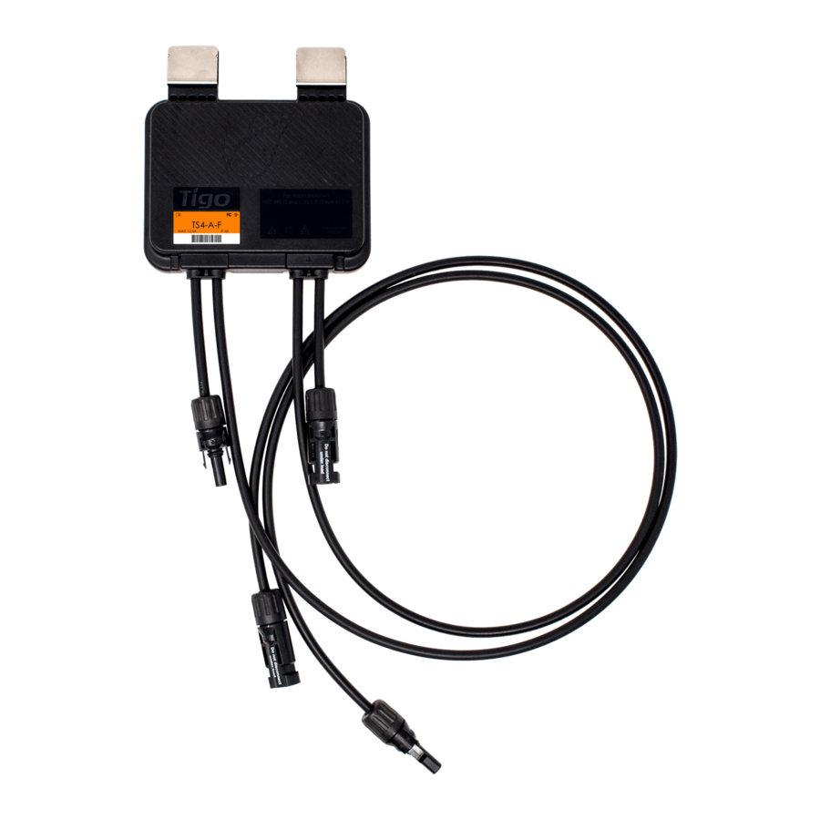
1.3 TS4-A-F Overview
1. PV module Input
2
•
Negative (-) LEFT
•
Positive (+) RIGHT
2. Output to String
•
Negative (-) LEFT
•
Positive (+) RIGHT
1
Max voltage: 80V
DC
Max current Imp/Isc: 20/25A
DC
Max power: 700W
Max string voltage: 1000/1500V
(connector dependent)
DC
Wear and USE appropriate PPE for the application.
!
Energy is supplied to the Tigo TS4 output cables immediately upon connection to a PV
!
module exposed to sunlight. Use care when handling. Do not mate connectors from
different manufacturers.
2. Installation
Install the TS4-A-F, and/or TS4-A-2F BEFORE powering on the RSS transmitter. All PV
!
modules from the same inverter must have a TS4 connected.
1. MOUNT
2. Connect MODULES to TS4s
TS4-A-F
TS4-A-F
1
2
Mounting the TS4 to the PV module frame and dressing the input conductors BEFORE taking the module to
the roof helps save time.
TS4-A-F Quick Start Guide
Pg 1 of 2
3.
Module clips
•
With clips on, mount
3
to PV module
•
Remove clips to
reveal M8 mounting
holes
TS4-A-F
3. Connect the TS4s
3
TS4-A-F
TS4-A-F
PN: 002-00101-00 | Rev. 1.1 | Oct. 26, 2022
Advertisement

Subscribe to Our Youtube Channel
Related Manuals for Tigo TS4-A-F


Summary of Contents for Tigo TS4-A-F
- Page 1 TS4-A-F TS4-A-F Many leading inverters integrate the Tigo RSS Transmitter. Look for the Tigo Enhanced label or check for Tigo Mounting the TS4 to the PV module frame and dressing the input conductors BEFORE taking the module to integration partners at https://www.tigoenergy.com/ul-pvrss...
- Page 2 Check that the RSS transmitter is powered on. If multiple transmitters are used, check that all Tigo RSS The Tigo RSS Transmitter is installed per the RSS Transmitter Installation Manual. If are of the Pure Signal Technology (PST) series and are properly wired.
Need help?
Do you have a question about the TS4-A-F and is the answer not in the manual?
Questions and answers