Advertisement
Quick Links
Dry Claw Vacuum Pump
CP 500/CP 1000
Operating instructions 301010146_002_C3
Part numbers
10790500V00
10790500V01
10791000V00
10791000V01
10790500V02
10790500V03
10790500V04
10791000V02
10791000V03
10791000V04
NEMA
1951001107
1951001108
1951001109
1951001110
Original instructions
Advertisement

Related Manuals for LEYBOLD CP 500


Summary of Contents for LEYBOLD CP 500
- Page 1 Dry Claw Vacuum Pump CP 500/CP 1000 Operating instructions 301010146_002_C3 Part numbers 10790500V00 10790500V01 10791000V00 10791000V01 10790500V02 10790500V03 10790500V04 10791000V02 10791000V03 10791000V04 NEMA 1951001107 1951001108 1951001109 1951001110 Original instructions...
- Page 2 Copyright notice ©Leybold GmbH. All rights reserved. Published: 11/5/2024 Trademark credit Leybold and the Leybold logo are trademarks of Leybold GmbH, Bonner Strasse 498, D-50968 Cologne. Disclaimer The content of this manual may change from time to time without notice.
- Page 3 6.1 Installation safety....... 39 6.2 Instructions for use......39 301010146_002_C3 - © Leybold 3...
- Page 4 8.3.10 Change the oil....... 78 8.3.11 Replace element (generator) shaft seal... . 4 301010146_002_C3 - © Leybold...
- Page 5 Disposal........87 301010146_002_C3 - © Leybold 5...
- Page 6 Figure 11. Transport and packaging CP 1000... . . 36 Figure 12. Unpack CP 500......37 Figure 13.
- Page 7 Figure 36. Motor installation......66 Figure 37. Motor installation motor mounted CP 500..68 Figure 38.
- Page 8 Major maintenance kit..... . . 81 Table 23: Major maintenance kit(NEMA)....81 8 301010146_002_C3 - © Leybold...
- Page 9 NOTICE: Information about properties or instructions for an action which, if ignored, will cause damage to the equipment. We reserve the right to change the design and the stated data. The illustrations are not binding. 301010146_002_C3 - © Leybold 9...
- Page 10 Risk of injury. Identifies spilled liquids, trailing cords, pipes and other low-lying objects that may result in slipping, tripping or falling. Mandatory action symbol Failure to comply with this action may result in injury or damage to equipment. 10 301010146_002_C3 - © Leybold...
- Page 11 The equipment must be discarded carefully. Obey local and national regulations for disposal of this equipment. Identifies compliant prod‐ uct supplied without a manufacturing date. Symbol - Protective earth Identifies an electrical equipment earth (ground) terminal. 301010146_002_C3 - © Leybold 11...
- Page 12 All the work must be done using protection gloves if the pump is still warm. WARNING: EXPLOSION HAZARD Risk of injury and damage to the equipment. The pump must not be installed and operated within explosion hazard areas. 12 301010146_002_C3 - © Leybold...
- Page 13 These precautions are applicable to the pump that process or use air or inert gas. When the pump is used with other gases, it is necessary to use more safety precautions. Some precautions are general and might not apply to your pump. 301010146_002_C3 - © Leybold 13...
- Page 14 "This pump may start without warning" 15. In multiple pump systems, manual valves must be installed to isolate each pump. Do not rely on Non-return valves (check valves) for isolating multiple systems. 14 301010146_002_C3 - © Leybold...
- Page 15 (canopy), ear protection must be worn near the pump. 6. If the pump is operated in a room where the sound pressure level is more than or equal to 80 dB(A), personnel must wear ear protectors. 301010146_002_C3 - © Leybold 15...
- Page 16 ▪ the pump is isolated from all sources of vacuum or overpressure ▪ ▪ the pump is at atmospheric pressure. ▪ 7. Do not use flammable solvents or carbon tetrachloride to clean the parts. Obey the safety precautions for toxic vapours of cleaning liquids. 16 301010146_002_C3 - © Leybold...
- Page 17 17. Do not use caustic solvents which can damage the materials of the air net, (for example, the polycarbonate bowls). 18. Faults or wearing of seals can cause leakage of oil lubricant. Prevent the dispersion in soil and pollution of the other materials. 301010146_002_C3 - © Leybold 17...
- Page 18 The ambient temperature must be between 5 °C to 40 °C (41 °F to 104 °F). The pump is contactless machines, enclosed in acoustic sound shied and designed to have cooling air passed through the sound shield by fan. The warm air is exhausted through the vent. 18 301010146_002_C3 - © Leybold...
- Page 19 Electric motors are 3 phase NEMA Premium multi‑voltage multi‑frequency type. The main motor options are: Voltage (V) Frequency (Hz) Certification 230/460 CSA CLASS/UL SAFE CSA CLASS/UL SAFE Accessories The pump is supplied with the following accessories: 301010146_002_C3 - © Leybold 19...
- Page 20 ▪ Outlet Silencer ANSI 4": 1951001159 ▪ 3.2.1 General pump view Figure 1. General pump view Bare Shaft CP 500 BS CP 1000 BS Inlet non-return valve Noise reducing canopy Drive motor connection flange Main silencer Air outlet Cooling air outlet 20 301010146_002_C3 - © Leybold...
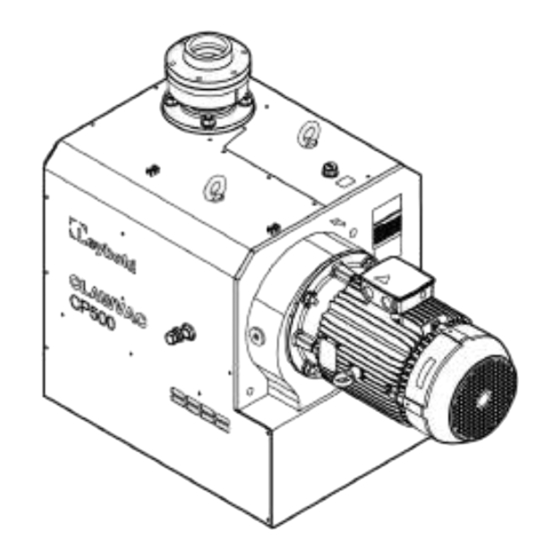
- Page 21 Inlet non-return valve Cooling air outlet Air outlet Main silencer Figure 3. General pump view Motor mount CP 500 CP 1000 Inlet non-return valve Noise reducing canopy Motor Main silencer Air outlet Cooling air outlet 301010146_002_C3 - © Leybold 21...
- Page 22 Air comes in through the air intake and non-return valve. The air is displaced by the vacuum pump element. After passing the element, the air enters the discharge silencer before exiting to the atmosphere. Figure 5. Flow diagram with vacuum relief valve 22 301010146_002_C3 - © Leybold...
- Page 23 Figure: Position of drain port (Motor mount)(NEMA) on page 25. You must obey your local regulations applicable for water drainage. Figure 6. Position of drain port (Bareshaft) CP 500 BS CP 1000 BS Drain port and drain valve 301010146_002_C3 - © Leybold 23...
- Page 24 General description Figure 7. Position of drain port (Bareshaft) (NEMA) CP500 BS CP1000 BS Drain port and drain valve Figure 8. Position of drain port (Motor Mount) CP 500 CP 1000 Drain port and drain valve 24 301010146_002_C3 - © Leybold...
- Page 25 General description Figure 9. Position of drain port (Motor mount)(NEMA) CP500 CP1000 Drain port and drain valve 301010146_002_C3 - © Leybold 25...
- Page 26 Table 3. Reference condition Parameters Unit Value Relative humidity °C Air inlet temperature °F mbar(g) <150 Exhaust back pressure <2.18 mbar(a) 1013 Ambient barometric pressure 14.7 Table 4. Limitations Parameters Unit Value °C Minimum ambient temperature °F 26 301010146_002_C3 - © Leybold...
- Page 27 The vacuum pump is designed to work constantly on a pressure from ultimate until atmospheric pressure. The maximum inlet pressure of the pump is 1050 mbar(a). In case of a higher inlet pressure, contact your pump manufacture. 301010146_002_C3 - © Leybold 27...
- Page 28 Table 7. Material of construction Component Material Note Coupling housing Aluminum casting Gear box Iron casting Pump chamber Iron casting PEEK coating inside End cover Iron casting PEEK coating inside 28 301010146_002_C3 - © Leybold...
- Page 29 CLAWVAC CP 1000 B 50Hz IEC FLANGE 10791000V01 CLAWVAC CP 1000 B 60Hz IEC FLANGE 10790500V02 CLAWVAC CP 500 400 V 50 Hz IE4 10790500V03 CLAWVAC CP 500 380 V 60 Hz IE4 10790500V04 CLAWVAC CP 500 460 V 60 Hz IE4...
- Page 30 Table: Currents and fuses. Leakage breaker (Customer Selected) If a leakage breaker is necessary for installation, use an all current sensitive leakage breaker, RCM or RCD Type B (refer to IEC/EN 60755) with a sufficient trip level. 30 301010146_002_C3 - © Leybold...
- Page 31 60364‑5‑52 - electrical installations of buildings part 5 - selection and erection equipment and section 52 - current carrying capacities in wiring systems. The permitted currents are valid for PVC insulated cables with three loaded copper conductors (maximum conductor temperature 70 °C (158 °F)). 301010146_002_C3 - © Leybold 31...
- Page 32 Installation method F as per the table B.52.1. Single-core cables, touching in free air clearance to wall not less than one cable diame‐ ter. Maximum permitted current in function of the ambient temperature for installation method F. 32 301010146_002_C3 - © Leybold...
- Page 33 If method C is used, 50 mm² is sufficient. (35 mm² for method F) =>cable 3 x 50 mm² + 25 mm². ▪ Parallel supply cable (2 x 3 phases + PE - configuration (2)): ▪ ▪ I = (89 A + 10%)/2 = (89 x 1.1)/2 = 49 A ▪ 301010146_002_C3 - © Leybold 33...
- Page 34 ▪ For supply cables larger than AWG8: use maximum permitted ▪ capacity. < 100 A: use AWG8 < 200 A: use AWG6 < 300 A: use AWG4 Always check the voltage drop over the cable (less than 5% of the nominal voltage is recommended). 34 301010146_002_C3 - © Leybold...
- Page 35 ▪ For an AWG4, the maximum current is 85 A x 0.8 = 68 A, ▪ which is not sufficient. For an AWG3, the maximum current is 100 x 0.8 = 80 A. So, 2 parallel cables of 3 x AWG3 + 2 x AWG8 are sufficient. ▪ Install 80 A fuses on each cable. ▪ 301010146_002_C3 - © Leybold 35...
- Page 36 Check the packaging on delivery for transport damages. The outer packaging is made of wood. Use a forklift to transport the pallet. Figure 10. Transport and packaging CP 500 Figure 11. Transport and packaging CP 1000 5.2 Unpack Wear gloves and protection glasses before you unpack the pump.
- Page 37 Transportation Figure 12. Unpack CP 500 Figure 13. Unpack CP 1000 5.3 Remove the pump The pump is fixed by strapping belts and some wooden blocks around rubber foot. Remove the belts and wooden blocks with enough protection. The pump is then ready to be shifted or lifted off the pallet.
- Page 38 ▪ Pump that has been filled with oil must only be moved in the upright ▪ position (horizontally). Otherwise, oil may escape. ▪ The angle of slope must not be more than 10 degrees. ▪ ▪ Avoid any other orientations while you move the pump ▪ 38 301010146_002_C3 - © Leybold...
- Page 39 ▪ Do not make changes to the pump by welding, drilling or by other ▪ mechanical methods without the written permission of the manufacturer. ▪ Only use oil as specified by the manufacturer. ▪ ▪ The pressure and temperature of the pump must be clearly indicated. ▪ 301010146_002_C3 - © Leybold 39...
- Page 40 Installation 6.3 Dimension drawings Figure 14. Vacuum pump dimensions - CP 500 BS, 50 Hz Dimension tolerances = ± 10 mm (0.4 inch). Lifting eye Air inlet Oil level indicator G3/4 Oil drain plug G1/2 Anti-vibration feet (x4) Oil filling Exhaust outlet...
- Page 41 Installation Figure 15. Vacuum pump dimensions - CP 500 BS, 60 Hz Dimension tolerances = ± 10 mm (0.4 inch). Lifting eye Air inlet Oil level indicator G3/4 Flange Oil drain plug G1/2 Anti-vibration feet (x4) Oil filling Exhaust outlet...
- Page 42 Dimension tolerances = ± 10 mm (0.4 inch). Lifting eye Thru plug installed G1/4 Inlet Oil drain plug G1/2 Oil level indicator G3/4 Outlet flange Drain valve Anti-vibration feet (x4) Exhaust outlet Cable mountings Oil filling Black plastic plug 42 301010146_002_C3 - © Leybold...
- Page 43 Dimension tolerances = ± 10 mm (0.4 inch). Lifting eye Thru plug installed G1/4 Inlet Oil drain plug G1/2 Oil level indicator G3/4 Outlet flange Drain valve Anti-vibration feet (x4) Exhaust outlet Cable mountings Oil filling Black plastic plug 301010146_002_C3 - © Leybold 43...
- Page 44 Figure 18. Vacuum pump dimensions - CP500 BS, 60 Hz (NEMA) Air inlet 3" NPT Oil level indicator G3/4 Oil drain plug G1/2 Exhaust outlet Drain valve Oil filling Cable mountings Lifting eye Outlet 2-1/2" NPT adaptor Anti-vibration feet (x4) Black plastic plug 44 301010146_002_C3 - © Leybold...
- Page 45 Inlet 4" ANSI 150# Thru plug installed G1/4 Oil drain plug G1/2 Oil level indicator G3/4 Outlet flange Drain valve Oil filling Exhaust outlet 4" ANSI 150# Cable mountings Lifting eye Anti-vibration feet (x4) Black plastic plug 301010146_002_C3 - © Leybold 45...
- Page 46 Installation Figure 20. CP 500 60 Hz 380 V Dimension motor shaft Dimension tolerances = ± 10 mm (0.4 inch). Lifting eye Inlet G3" Black plastic plug Outlet G2-1/2 adaptor Oil level indicator G3/4 Oil drain plug G1/2 Drain valve G3/8"...
- Page 47 Installation Figure 21. CP 500 50 Hz 400 V Dimension motor shaft Dimension tolerances = ± 10 mm (0.4 inch). Lifting eye Inlet G3" Black plastic plug Outlet G2-1/2 adaptor Oil level indicator G3/4 Oil drain plug G1/2 Drain valve G3/8"...
- Page 48 Installation Figure 22. CP 500 60 Hz 460 V Dimension motor shaft Dimension tolerances = ± 10 mm (0.4 inch). Lifting eye Inlet G3" Black plastic plug Outlet G2-1/2 adaptor Oil level indicator G3/4 Oil drain plug G1/2 Drain valve G3/8"...
- Page 49 Black plastic plug Lifting eye Inlet Cooling air outlet G1/4 thru plug Oil drain plug G1/2 Oil level indicator G3/4 Outlet flange DN 100 PN10 Drain valve G1/2" Oil filling Cable mountings 4X Anti vibration feet 301010146_002_C3 - © Leybold 49...
- Page 50 Inlet DN 100 PN6 G1/4 thru plug Oil drain plug G1/2 Oil level indicator G3/4 Outlet flange DN 100 PN10 Drain valve G1/2" 4X anti vibration feet Ø75 X M12 X Oil filling Cable mountings Cooling air outlet 50 301010146_002_C3 - © Leybold...
- Page 51 Black plastic plug Lifting eye Inlet Cooling air outlet G1/4 Thru plug Oil drain plug G1/2 Oil level indicator G3/4 Outlet flange DN 100 PN10 Drain valve G1/2" Oil filling Cable mountings 4X Anti vibration feet 301010146_002_C3 - © Leybold 51...
- Page 52 Figure 26. CP500 60 Hz 230-460 V Dimension motor shaft(NEMA) Inlet 3" NPT Oil level indicator G3/4 Oil drain plug G1/2 Exhaust outlet Drain valve G3/8" Oil filling Cable mountings Lifting eye Outlet 2-1/2" NPT adaptor Anti-vibration feet (x4) Black plastic plug 52 301010146_002_C3 - © Leybold...
- Page 53 CP 1000 1169 1274 50.17 17.8 25.5 13.5 BS(50 Hz)* CP 1000 1169 1274 50.17 17.8 25.5 13.5 BS(60 Hz)* CP 500 50 Hz 1250 400 V * CP 500 60 Hz 1302 380 V* 301010146_002_C3 - © Leybold 53...
- Page 54 CAUTION: HOT SURFACE Risk of burn injury. The pump surface and exhaust gas will be hot. You must consider the safety of personnel when the pump is installed. 54 301010146_002_C3 - © Leybold...
- Page 55 ▪ Allow access to the oil sight glass in order to inspect the oil level ▪ regularly, and the oil fill and oil drain port for easy service. 301010146_002_C3 - © Leybold 55...
- Page 56 If this is not possible, install a correctly sized vessel. ▪ The pipes must be straight with no tight bends, fold or twists. The ▪ pipes should be sized correctly to decreases the losses. Use the same 56 301010146_002_C3 - © Leybold...
- Page 57 ▪ Qv = Necessary cooling air flow (m /s), (CFM) ▪ ▪ N = Nominal motor power of the pump (kW), (Hp) ▪ ▪ T = Temperature increase in the pump room (°C), (°F) ▪ 301010146_002_C3 - © Leybold 57...
- Page 58 The inlet filter must be installed in a horizontal position to prevent filtered dust falling into the pump inlet. Figure 29. Inlet filter installation CP 500 BS CP 1000 BS Inlet filter 58 301010146_002_C3 - © Leybold...
- Page 59 The inlet filter must be installed in a horizontal position to prevent filtered dust falling into the pump inlet. Figure 31. Inlet filter installation (NEMA) CP500 BS CP1000 BS Inlet filter 301010146_002_C3 - © Leybold 59...
- Page 60 (canopy) parts or lifting supports are not fully installed. When the pump is being lifted, do not stand below the load or do the maintenance work Caution the lifting angle will change if the pump installed with motor, inverter or accessories. 60 301010146_002_C3 - © Leybold...
- Page 61 ▪ The motor is also equipped with an eyebolt but it is designed only for ▪ the motor. You must use the eyebolt installed at the pump for lifting the pump assembly. Do not use the motor eyebolt. Figure 33. Pump lifting eye Lifting eye 301010146_002_C3 - © Leybold 61...
- Page 62 (Lockout/Tagout). To prevent the pump from operating unexpectedly after a mains power failure, the pump must be integrated with the control system in such a way that the pump can only be switched on again manually. This applies equally to the emergency cut-out arrangements. 62 301010146_002_C3 - © Leybold...
- Page 63 If you use a 60 Hz motor in combination with a 50 Hz pump, it will result in too low ultimate pressure levels. This can lead to seizing of the air end. 301010146_002_C3 - © Leybold 63...
- Page 64 CP1000 22/30 44.5 2.48 * According to DIN 6885 # As per standard IEC-72 (1) Minimum power and torque required at the motor shaft, efficiency of drive motor still has to be taken into consideration. 64 301010146_002_C3 - © Leybold...
- Page 65 If the direction is wrong, switch off the voltage and reverse two incoming electric lines. To install the motor, refer to Figure: Motor installation and do the steps that follow: 301010146_002_C3 - © Leybold 65...
- Page 66 Table 18. Motor installation Part number Motor description Ø38 k6 (+0.018) MOTOR 9.2 kW 2P 10790500V00 8±0.2 -0.3 L132M/L 50 Hz (+0.002) Ø42 k6 (+0.018) MOTOR 11 kW 2P 160M 10790500V01 6±0.2 -0.3 60 Hz (+0.002) 66 301010146_002_C3 - © Leybold...
- Page 67 4. If the dimension Y on selected motor is different with the data in upper table, the distance shall be calculated based on data Z or contact our sales team. 5. Motor conforms to IEC60034-1 301010146_002_C3 - © Leybold 67...
- Page 68 Installation Figure 37. Motor installation motor mounted CP 500 Coupling element Coupling Motor Washer x 4 Hex head screw x 4 Set screw Figure 38. Motor installation motor mounted CP 1000 Coupling element Coupling Motor Washer x 4 Hex head screw x 4 Set screw 68 ...
- Page 69 Installation 6.7 Pictographs Figure 39. Pictograph Warning: Voltage Warning: Hot surface Rotation direction of fan 301010146_002_C3 - © Leybold 69...
- Page 70 5. Check the oil level. The minimum level should reach the oil sight glass when the pump is stopped. If needed, top up the oil. 6. Take care that no dirt drops into the oil system. Refit and tighten the filler plug. 70 301010146_002_C3 - © Leybold...
- Page 71 WARNING: OPERATION SAFETY Risk of injury or damage to the pump. Before starting the pump make sure that the pump and the fitted accessories meet the requirements of your application and that safe operation can be guaranteed. 301010146_002_C3 - © Leybold 71...
- Page 72 2. Pour oil in the gearbox. Make sure that the oil is not above the maximum oil level marked on Figure: Oil level warning label. We recommend G+ Xpand 150 oil. 3. Close the filler plug. 4. Remove all oil spills on the pump and the floor. 72 301010146_002_C3 - © Leybold...
- Page 73 7.5 Taking out of operation To take the pump out of operation, set the voltage to off and disconnect the pump from the mains power supply. 301010146_002_C3 - © Leybold 73...
- Page 74 In case of special designs and variants please always indicate the serial number. 8.2 Maintenance intervals Note: The intervals stated in the maintenance schedule are approximate values for normal pump operation. Unfavourable ambient conditions and/or aggressive media may significantly reduce maintenance intervals. 74 301010146_002_C3 - © Leybold...
- Page 75 8.3 Maintenance work Before you do the maintenance, repair or adjustment: 1. Stop the pump. 2. Close the isolation valve and wait for 3 minutes. 3. Push the emergency stop button and set the voltage to off. 301010146_002_C3 - © Leybold 75...
- Page 76 Contact your pump manufacturer to align your preventive maintenance needs and guarantee your Warranty/ Product Liability coverage. For an overhaul or repair the claw pump, contact us. 76 301010146_002_C3 - © Leybold...
- Page 77 Refer to Table: Coupling unit kit for more information. Inspection hole with G1" plug: Check the coupling and fan through this hole regularly (the endoscope (WireCam) can be used with smart phone software). 301010146_002_C3 - © Leybold 77...
- Page 78 We recommend G+ Xpand 150 oil fluid which is specially developed lubricant for use in the gearbox of the pump. Its specific composition keeps the pump in excellent condition.Refer to Table: Maintenance interval 78 301010146_002_C3 - © Leybold...
- Page 79 Risk of electric shock. Before starting the pump,you must disconnect the motor from the power supply. The motor can only be changed with an identical one from the same manufacture and marketing. In case other motors are used, the pump loses its CE certification. 301010146_002_C3 - © Leybold 79...
- Page 80 Download the latest documents from leybold.com/en/downloads/ download-documents/declaration-of-contamination/, follow the procedure in HS1, fill in the electronic HS2 form, print it, sign it, and return the signed copy to us. 80 301010146_002_C3 - © Leybold...
- Page 81 G+ Xpand 150 oil Includes oil Table 22. Major maintenance kit Part number Part description Remark EK6549603 Major maintenance kit CP 500 Includes sleeve, piston ring, bearing, shaft seals, EK6549605 Major maintenance kit CP 1000 O-rings, gaskets etc. Table 23. Major maintenance kit(NEMA)
- Page 82 Too high pressure drop between process and pump inlet (Vacuum pump) or pump outlet (Overpressure pump) Remedy Check the process lines for correct size and for leakage. Correct if necessary Cause The pump element is out of order Remedy Contact us for support. 82 301010146_002_C3 - © Leybold...
- Page 83 Carry over from process contamination Remedy Install the liquid separator. Cause High oil level in gearbox Remedy Lower the oil level. Cause Lipseal wear or failure Remedy Do the lipseal overhaul on the element side 301010146_002_C3 - © Leybold 83...
- Page 84 Inlet screen (mesh) in the vacuum regulator clogged with debris Remedy Clean screen (mesh) and check inlet filter element. Cause Vacuum regulator set over the set point or is out of order Remedy Set the point again or replace it with new one 84 301010146_002_C3 - © Leybold...
- Page 85 Use the bigger diameter pipe and shorten the lines length if possible. Fault The pump will not operate (seized up) Cause Rotary claws, bearings or gears stuck on Remedy Call service agent for service or exchange program. 301010146_002_C3 - © Leybold 85...
- Page 86 30 minutes after every 6 months. Long term storage If the pump is put into storage for long term, make sure to follow all precautions. Contact us when it is necessary to start the pump or when you do decommissioning. 86 301010146_002_C3 - © Leybold...
- Page 87 Disposal 11 Disposal Obey all the local and national safety and environmental regulations when you discard service liquid and all other used materials (for example, dirty rags and machine parts). 301010146_002_C3 - © Leybold 87...
- Page 88 Directive 2006/42/EC on Machinery. Product: Dry Claw Vacuum Pump, Bareshaft Models: CLAWVAC CP 500 BS, IEC 50Hz flange; CLAWVAC CP 500 BS, IEC 60Hz flange; CLAWVAC CP 1000 BS, IEC 50Hz flange; CLAWVAC CP 1000 BS, IEC 60HZ flange 10790500V00;...
- Page 89 Supply of Machinery (Safety) Regulations 2008. Product: Dry Claw Vacuum Pump, Bareshaft Models: CLAWVAC CP 500 BS, IEC 50Hz flange; CLAWVAC CP 500 BS, IEC 60Hz flange; CLAWVAC CP 1000 BS, IEC 50Hz flange; CLAWVAC CP 1000 BS, IEC 60HZ flange 10790500V00;...
- Page 90 ADDITIONAL LEGISLATION AND COMPLIANCE INFORMATION RoHS (EU, UK): Material Exemption Information This product is compliant with the following Exemptions Annex III: • 6(a) Lead as an alloying element in steel for machining purposes and in galvanised steel containing up to 0.35 % lead by weight •...
- Page 91 • Pump code and model: Bare shaft version – without motor 10790500V00: CLAWVAC CP 500 B 50Hz IEC FLANGE 10790500V01: CLAWVAC CP 500 B 60Hz IEC FLANGE 10791000V00: CLAWVAC CP 1000 B 50Hz IEC FLANGE 10791000V01: CLAWVAC CP 1000 B 60Hz IEC FLANGE Motorized version –...
- Page 92 • Pump code and model: Bare shaft version – without motor 10790500V00: CLAWVAC CP 500 B 50Hz IEC FLANGE 10790500V01: CLAWVAC CP 500 B 60Hz IEC FLANGE 10791000V00: CLAWVAC CP 1000 B 50Hz IEC FLANGE 10791000V01: CLAWVAC CP 1000 B 60Hz IEC FLANGE Motorized version –...
- Page 93 ADDITIONAL LEGISLATION AND COMPLIANCE INFORMATION EMC (EU, UK): Industrial equipment Caution: This equipment is not intended for use in residential environments and may not provide adequate protection to radio reception in such environments. RoHS (EU, UK): Material Exemption Information This product is compliant with the following Exemptions Annex III: •...
- Page 94 材料成分声明 China Material Content Declaration 有害物质 Hazardous Substances 部件名称 六价铬 多溴联苯 多溴二苯醚 铅 汞 镉 Part name Hexavalent Polybrominated Polybrominated Lead Mercury Cadmium Chromium biphenyls diphenyl ethers (Pb) (Hg) (Cd) (Cr VI) (PBB) (PBDE) 铸铝及铝合金制品 Aluminium alloys 钢合金制品 Steel alloys 铜接头...
- Page 95 This page has been intentionally left blank.
- Page 96 Leybold GmbH Bonner Strasse 498 50968 Cologne GERMANY +49-(0)221-347-0 info@leybold.com Pioneering products. Passionately applied. www.leybold.com...
Need help?
Do you have a question about the CP 500 and is the answer not in the manual?
Questions and answers