Advertisement
Available languages
Available languages
Quick Links
Operator's Manual
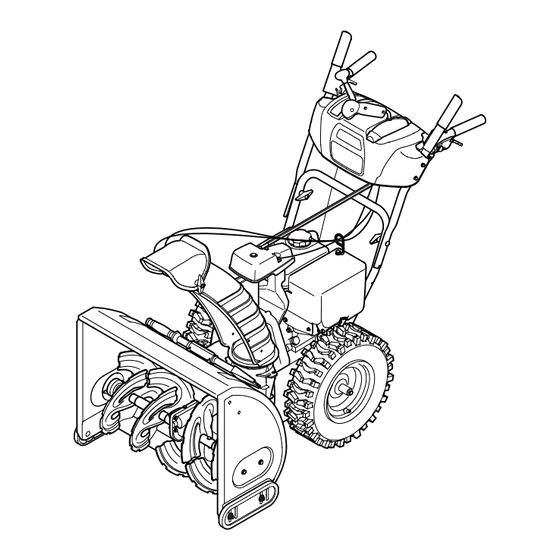
26" SNOW THROWER
Model No. 247.88691
CAUTION: Before using
this product, read this
manual and follow all
safety rules and operating
instructions.
Sears, Roebuck and Co., Hoffman Estates, IL 60179, U.S.A.
®
Visit our website: www.craftsman.com
• SAFETY
• ASSEMBLY
• OPERATION
• MAINTENANCE
• PARTS LIST
• ESPAÑOL
FORM NO. 769-05134A
9/18/2009
Advertisement

Subscribe to Our Youtube Channel
Related Manuals for Sears CRAFTSMAN 247.88691


Summary of Contents for Sears CRAFTSMAN 247.88691
- Page 1 • MAINTENANCE • PARTS LIST CAUTION: Before using • ESPAÑOL this product, read this manual and follow all safety rules and operating instructions. Sears, Roebuck and Co., Hoffman Estates, IL 60179, U.S.A. Visit our website: www.craftsman.com FORM NO. 769-05134A 9/18/2009...
- Page 2 When operated and maintained according to all supplied instructions, if this Craftsman snow thrower fails due to a defect in material or workman- ship within two years from the date of purchase, return it to any Sears store, Sears Parts & Repair Service Center, or other Craftsman outlet in the United States for free repair (or replacement if repair proves impossible).
- Page 3 SAFETY INSTRUCTIONS Warning Danger This machine was built to be operated according to the safe opera- This symbol points out important safety instructions which, if not tion practices in this manual. As with any type of power equipment, followed, could endanger the personal safety and/or property of carelessness or error on the part of the operator can result in serious yourself and others.
- Page 4 SAFETY INSTRUCTIONS Safe Handling of Gasoline • Exercise extreme caution when operating on or crossing gravel surfaces. Stay alert for hidden hazards or traffic. To avoid personal injury or property damage use extreme care in handling gasoline. Gasoline is extremely flammable and the vapors are •...
- Page 5 Observe proper disposal laws and regulations for gas, oil, etc. to states may have similar laws. Federal laws apply on federal lands. protect the environment. A spark arrester for the muffler is available through your nearest Sears Parts and Repair Service Center. •...
- Page 6 SAFETY INSTRUCTIONS safety symbols This page depicts and describes safety symbols that may appear on this product. Read, understand, and follow all instructions on the machine before attempting to assemble and operate. Symbol Description READ THE OPERATOR’S MANUAL(S) Read, understand, and follow all instructions in the manual(s) before attempting to assemble and operate WARNING—...
- Page 7 SAFETY LABELS DANGER NEVER PUT HAND IN CHUTE. CONTACT WITH ROTATING PARTS CAN AMPUTATE FINGERS AND HANDS. SHUT OFF ENGINE AND WAIT UNTIL ALL MOVING PARTS HAVE STOPPED BEFORE UNCLOGGING. USE CLEAN-OUT TOOL OR WOODEN STICK TO UNCLOG DISCHARGE CHUTE.
- Page 8 ASSEMBLY NOTE: References to right or left side of the snow thrower are determined from behind the unit in the operating position (standing directly behind the snow thrower, facing the handle panel). Chute Control Head remoVing from Carton Chute Support Cut the corners of the carton and lay the sides flat on the ground.
- Page 9 ASSEMBLY Place chute onto chute base and ensure hex rod is positioned Chute Control under handle panel. Install hex bolt previously removed but do Top View Input not secure with wing nut at this time. See Figure 4. Squeeze the trigger on the handle panel joystick and rotate the chute by hand to face forward.
- Page 10 ASSEMBLY 7. Insert the hex end of chute rod into the input shaft below joystick on handle panel. Make sure to line up the hole in the hex end of chute rod with the arrow on the input shaft. See Figure 7. NOTE: The chute rod will fit snuggly into the input shaft.
- Page 11 ASSEMBLY 10. Check that all cables are properly routed through the cable guide on the engine. See Figure 10. NOTE: For smoothest operation, the cables should all be to the left of the chute control rod. 11. The extension cord for the electric starter is fastened with a cable tie to the rear of the auger housing for shipping purposes.
- Page 12 ASSEMBLY Chute Clean-out tool A chute clean-out tool is fastened to the top of the auger housing with a mounting clip. See Figure 12. The tool is designed to clear a chute assembly of ice and snow. This item is fastened with a cable tie at the factory.
- Page 13 ASSEMBLY auger Control Warning Prior to operating your snow thrower, carefully read and follow all instructions below. Perform all adjustments to verify your snow thrower is operating safely and properly. Check the adjustment of the auger control as follows: When the auger control is released and in the disengaged “up” position, the cable should have very little slack.
- Page 14 OPERATION Shift lever Drive Control four-Way Chute Control™ (Joystick) auger Control Gas Cap Wheel Steering Control Chute assembly Recoil Starter Handle Clean Out Primer Tool Oil fill Throttle Control Choke Control Electric Start Button Oil Drain Electric Starter Outlet augers Skid Shoe Figure 15 NOTE: Do not turn the key in an attempt to start the engine.
- Page 15 OPERATION tHrottle Control The auger control is located on the left handle. Squeeze the control grip against the handle to engage the auger and start snow throwing action. Release to stop. DriVe Control/ auger Control loCk The throttle control is located on the rear of the engine. It regulates the DRIVE speed of the engine and will shut off the engine when moved into the CONTROL...
- Page 16 OPERATION Clean-out tool • Refuel in a well-ventilated area with the engine stopped. Do not smoke or allow flames or sparks in the area where the engine is Warning refueled or where gasoline is stored. • Do not overfill the fuel tank. After refueling, make sure the tank Never use your hands to clear a clogged chute assembly.
- Page 17 Caution Push primer three (3) times, making sure to cover vent hole when NEVER replace the auger shear pins with anything other than Sears pushing. If engine is warm, push primer only once. Always cover SKU# 88389/OEM Part No. 738-04124A replacement shear pins.
- Page 18 Use the Service Log column to keep track of a complete stop. Disconnect spark plug wire and ground it against the completed maintenance tasks. To locate the nearest Sears Service engine to prevent unintended starting. Always wear safety glasses during Center or to schedule service, simply contact Sears at 1-800-4-MY-HOME®.
- Page 19 SERVICE AND MAINTENANCE Reinstall the drain plug and tighten it securely. Refill with the recommended oil and check the oil level. Recommended Oil Usage chart. The engine’s oil capacity is 37 ounces. Synthetic 0W-30 5W-30 -40º -20º 0º 20º 40º Oil Drain -30º...
- Page 20 SERVICE AND MAINTENANCE CAUTION The spark plug must be tightened securely. A loose spark plug can become very hot and can damage the engine. LUbRICATION Gear Shaft The gear (hex) shaft should be lubricated at least once a season or after every 25 hours of operation.
- Page 21 SERVICE AND MAINTENANCE ADjUSTMENTS Shift Cable If the full range of speeds (forward and reverse) cannot be achieved, refer to the figure to the right and adjust the shift cable as follows: Place the shift lever in the fastest forward speed position (F6). Loosen the hex nut on the shift cable index bracket.
- Page 22 SERVICE AND MAINTENANCE Auger Control Refer to the Assembly section for instructions on adjusting the auger control cable. Skid Shoes Refer to the Assembly section for instructions on adjusting the skid shoes. bELT REPLACEMENT Auger belt To remove and replace your snow thrower’s auger belt, proceed as follows: To prevent spillage, remove all fuel from tank by running engine until it stops.
- Page 23 NOTE: Several components must be removed and special tools are required in order to replace this snow thrower’s friction wheel rubber. If your friction wheel rubber needs to be replaced, contact the nearest Sears Parts & Repair Center. Stop Bolt Figure 33...
- Page 24 OFF-SEASON STORAGE If the snow thrower will not be used for 30 days or longer, or if it is the end of the snow season when the last possibility of snow is gone, the equipment needs to be stored properly. Follow storage instructions below to ensure top performance from the snow thrower for many more years. PreParing snoW tHroWer PreParing engine •...
- Page 25 Loose parts or damaged auger. Stop engine immediately and disconnect spark plug wire. Tighten all bolts and nuts. If vibration continues, have unit serviced by a Sears Parts & Repair Center. Loss of power Spark plug wire loose. Connect and tighten spark plug wire.
- Page 26 PARTS LIST Craftsman snow thrower model 247.88691 9 19...
- Page 27 PARTS LIST Craftsman snow thrower model 247.88691 Ref. No. Part No. Description Ref. No. Part No. Description 731-2635 Snow Removal Tool Mount 684-04107-0637 Spiral Assembly, LH 684-04057A -0637 Impeller Assembly, 12” Dia. 684-04108-0637 Spiral Assembly, RH 710-0347 Hex Screw, 3/8-16, 1.75, Gr5 731-04870 Spacer, 1.25 OD x .75 ID x 1.00 710-0451...
- Page 28 PARTS LIST Craftsman Snow Thrower Model 247.88691...
- Page 29 PARTS LIST Craftsman Snow Thrower Model 247.88691 Ref. No. Part No. Description Ref. No. Part No. Description 684-04112B Handle Engagement Assembly RH 731-04427A Upper Chute 738-04367 Flange Shoulder Screw 918-04801 4-Way Chute Gearbox Assembly 731-04894D Lock Plate 710-04187 Hi-Lo Screw, 1/4-15 x 0.5 684-04250 Pivot Rod 984-04338...
- Page 30 PARTS LIST Craftsman snow thrower model 247.88691 6 17...
- Page 31 PARTS LIST Ref. No. Part No. Description Ref. No. Part No. Description 710-1652 AB Screw, 1/4-20 x 0.625 918-04322A Drive Shaft Assembly 731-05353 Belt Cover 684-04159 Friction Wheel Assembly 735-04099 Plug, 3/8 ID 716-0136 Retainer Ring 711-1268B Actuator Shaft 726-0221 Speed Nut 746-04229 Drive Clutch Cable...
- Page 32 PARTS LIST Craftsman Engine Model ZS370-SUB For Snow Thrower Model 247.88691 109 117 69 64 23 23 18 15 13 14 37 37...
- Page 33 PARTS LIST Craftsman Engine Model ZS370-SUB For Snow Thrower Model 247.88691 Ref. Part No. Description Ref. Part No. Description 951-11012 Bolt 951-11371 Crankcase Cover Gasket 951-11054 Valve Cover 710-04932 Bolt 731-07059 Breather Hose 951-11368 Oil Seal 726-04101 Hose Clamp 736-04440 Washer 751-11124 Pivot Locking Nut...
- Page 34 PARTS LIST Craftsman Engine Model ZS370-SUB For Snow Thrower Model 247.88691 Ref. Part No. Description Qty. Ref. Part No. Description Qty. 715-04088 Dowel Pin — 951-11060A Short Block Assembly (Not Shown) — 951-10645A Electric Starter — Head Cover Gasket 710-05003 Bolt 951-11289 Muffler Gasket...
- Page 35 PARTS LIST Craftsman Engine Model ZS370-SUB For Snow Thrower Model 247.88691 Ref. Part No. Description Qty. Ref. Part No. Description Qty. — 951-11021 Carburetor Kit, Major (Not Shown) — — 951-10668A Cylinder Head Assembly (Not Shown) — — Gasket, Throttle Plate —...
- Page 36 PARTS LIST Craftsman snow thrower model 247.88691 777S32636 777D11443 CHUTE CONTROL CHUTE CONTROL 777S32236 777I22339 777D11431 777D12683 777I22363 777D12657 777X43688 777I22430 777D13768...
- Page 37 NOTES...
- Page 38 mtD Consumer grouP inC (mtD), the California air resources board (Carb) and the united states environment Protection agency (u. s. ePa) emission Control system Warranty statement (owner’s Defect Warranty rights and obligations) EMISSION CONTROL SYSTEM COVERAGE IS APPLICABLE TO CERTIFIED ENGINES PURCHASED IN CALIFORNIA IN 2005 AND THERE- AFTER, WHICH ARE USED IN CALIFORNIA, AND TO CERTIFIED MODEL YEAR 2005 AND LATER ENGINES WHICH ARE PURCHASED AND USED ELSEWHERE IN THE UNITED STATES.
- Page 39 (4) Repair or replacement of any warranted part under the warranty provisions of this article must be performed at no charge to the owner at a warranty station. (5) Notwithstanding the provisions of Subsection (4) above, warranty services or repairs must be provided at all MTD distribution centers that are franchised to service the subject engines.
- Page 40 1, 2000, look for emissions Compliance Period on engine emissions Compliance label After July 1, 2000 certain Sears, Roebuck and Co., U.S.A. engines will be certified to meet the United States Environmental Protection Agency (USEPA) Phase 2 emission standards. For Phase 2 certified engines, the Emis- sions Compliance Period referred to on the Emissions Compliance label indicates the number of operating hours for which the engine has been shown to meet Federal emission requirements.
- Page 41 U.S.A. or • Fast help by phone – we call it Rapid Resolution – phone support Canada call 1-800-4-MY-HOME®. from a Sears representative. Think of us as a “talking owner’s manual.”...
- Page 42 Cuando hecho funcionar y mantenido según todas las instrucciones suministradas, si este lanzador de nieve falla debido a un defecto en mate- rial o habilidad dentro de dos años de la fecha de compra, regresar a cualquier tienda Sears, Sears partes del Centro de Servicio y Reparación, Artesano o de otro tipo de salida en los Estados Unidos para la reparación gratuita (si la reparación o la sustitución resulte imposible).
- Page 43 INSTRUCCIONES DE SEGURIDAD aDVertenCia Peligro Esta máquina fue construida para ser operada de acuerdo con La presencia de este símbolo indica que se trata de instrucciones las reglas de seguridad contenidas en este manual. Al igual que importantes de seguridad que se deben respetar para evitar con cualquier tipo de equipo motorizado, un descuido o error por poner en peligro su seguridad personal y/o material y la de otras parte del operador puede producir lesiones graves.
- Page 44 INSTRUCCIONES DE SEGURIDAD Manejo seguro de la gasolina • Nunca opere la máquina si falta un montaje del canal o si el mismo está dañado. Mantenga todos los dispositivos de seguri- Para evitar lesiones personales o daños materiales tenga mucho dad en su lugar y en funcionamiento.
- Page 45 INSTRUCCIONES DE SEGURIDAD • Para encender el motor, jale de la cuerda lentamente hasta que • Según la Comisión de Seguridad de Productos para el Consu- sienta resistencia, luego jale rápidamente. El repliegue rápido de midor de los Estados Unidos (CPSC) y la Agencia de Protección la cuerda de arranque (tensión de retroceso) le jalará...
- Page 46 INSTRUCCIONES DE SEGURIDAD símbolos De seguriDaD Esta página describe los símbolos y figuras de seguridad internacionales que pueden aparecer en este producto. Lea el manual del operador para obtener la información terminada sobre seguridad, reunirse, operación y mantenimiento y reparación. Símbolo Descripción LEA EL MANUAL DEL OPERADOR (S)
- Page 47 MONTAJE NOTA: las referencias al lado derecho o y ciertos de la máquina quitanieve se determinan desde la parte posterior de la unidad en Cabezal de posición de operación (permaneciendo directamente detrás de la Control del máquina quitanieve, mirando hacia el panel de la manija). Canal Ménsula extraCCión De la uniDaD De la Caja...
- Page 48 MONTAJE 4. Ubique el canal sobre la base del mismo y garantizar la varilla hex Cabezal de agonal está situado bajo el panel manejar. Instalar el perno Control del Vista desde Arriba hexagonal previamente eliminado, pero no seguro con tuerca de Canal mariposa en este momento.
- Page 49 MONTAJE 7. Inserte la varilla hexagonal dentro del engranaje del piñón por debajo de la palanca de control. Asegúrese de alinear el orificio en la varilla hexagonal con la flecha en el engranaje del piñón. Vea la figura 7. NOTA: El orificio es una referencia para alinear la varilla con la flecha indicadora en el engranaje del piñón.
- Page 50 MONTAJE 10. Controle que todos los cables estén adecuadamente dirigidos a través de la guía de cables en el motor. Vea la figura 10. NOTA: Para más suave funcionamiento, los cables deben estar a la izquierda de la varilla hexagonal. 11.
- Page 51 MONTAJE Herramienta de limpieza del Canal Hay una herramienta de limpieza del canal iajustada a la parte superior de la caja de la barrena con un pasador de ensamblado. Vea la figura 12. La herramienta está diseñada para limpiar el hielo y la nieve del montaje de un canal.
- Page 52 MONTAJE NOTA: Si tiene que usar la máquina quitanieve sobre grava, mantenga la zapata antideslizante en la posición más elevada para lograr una separación máxima entre el piso y la placa de raspado. Para ajustar las zapatas antideslizantes: Afloje las cuatros tuercas hexagonales (dos en cada lado) y los pernos del carro.
- Page 53 OPERACIÓN Palanca de Cambios Control de Transmisión Control del canal de 4 direcciones™ Control de la Barrena Tapón de combustible Rueda que Conduce Mando Montaje del canal Manija del arrancador Silenciador de retroceso Herramienta de Cebador limpieza del canal llave llendo aceite Control del...
- Page 54 OPERACIÓN Control Del regulaDor Control De la barrena CONTROL DE LA BARRENA El control del regulador está ubicado en la parte trasera del motor. Regula la velocidad del motor, y lo apaga cuando se lo coloca en la posición STOP (detención). manija Del arranCaDor De retro- Ceso Esta manija se utiliza para arrancar el motor manualmente.
- Page 55 OPERACIÓN rueDa que ConDuCe manDos Vuelva a ajustar la herramienta de limpieza al pasador de en- samblado ubicado en la parte posterior de la caja de la barrena, La rueda izquierda y derecha que conduce mandos es localizada en la inserte de nuevo la llave de encendido y encienda el motor de la parte oculta de los mangos.
- Page 56 OPERACIÓN • No llene en exceso el tanque de combustible. Después de cargar Determine si el cableado de su hogar es un sistema de tres cables combustible, asegúrese de que el tapón del tanque esté bien conectado a tierra. Consulte con un electricista matriculado si no está cerrado y asegurado.
- Page 57 OPERACIÓN DetenCión Del motor arrancador de retroceso Deje encendido el motor durante algunos minutos antes de detenerlo PreCauCión para permitir que se seque la humedad en el mismo. No tire de la manija del arrancador mientras el motor está en marcha. Mueva el control del regulador a la posición OFF.
- Page 58 SERVICIO Y MANTENIMIENTO LiSta de ManteniMiento adVertenCia Antes de realizar cualquier tipo del mantenimiento/servicio, suelte Siga la lista de mantenimiento dada abajo. Esta carta describe pautas todos los mandos y pare el motor. Espere hasta que todas las partes de servicio sólo. Use la columna de Tronco de Servicio para guardar de movimiento hayan venido a una parada completa.
- Page 59 El aceite usado es un residuo peligroso. Elimine el aceite usado adecuadamente. No lo arroje junto con los residuos domiciliarios. Consulte a las autoridades locales o al centro de servicio Sears para averiguar dónde hay instalaciones para la eliminación/ reciclaje segura(o) del aceite usado.
- Page 60 SERVICIO Y MANTENIMIENTO Mida l a separación de bujía con un calibrador. Corrija de ser necesario torciendo el electrodo lateral. Vea la Figura 19. La separación debe establecerse entre 0,02 y 0,03 pulgadas (0,60- Electrodo 0,80 mm). Verifique que la arandela de la bujía esté en buenas condiciones y enrósquela manualmente para no estropear la rosca.
- Page 61 SERVICIO Y MANTENIMIENTO NOTA: Las zapatas de esta máquina tienen dos bordes de desgaste. Cuando un lado se desgasta, se las puede rotar 180º para usar el otro borde. Para retirar las zapatas antideslizantes: Quite los cuatro pernos del carro, arandelas (si corresponde), y las tuercas de brida hexagonales que los aseguran a la máquina quitanieve.
- Page 62 SERVICIO Y MANTENIMIENTO Ubique la ménsula hacia arriba para brindar más juego (o hacia abajo para aumentar la tensión del cable). Vuelva a apretar la tuerca hexagonal superior y repetir los pasos 1 a 4. Varilla de control del canal Para lograr una mayor engagment varilla hexagonal en el piñón de artes en el marco del panel de manejar, es necesario ajustar la varilla de control del canal.
- Page 63 SERVICIO Y MANTENIMIENTO Gire con cuidado la máquina quitanieve hacia arriba y hacia delante de manera que quede apoyada sobre la caja de la barrena. Saque la cubierta del marco desde debajo de la máquina quitanieve retirando los tornillos autorroscantes que la aseguran. Vea la figura 28.
- Page 64 Si necesita reemplazar la goma de su rueda Parada de fricción, contacte con el centro de partes y reparación Sears más cercano según las instrucciones de la página 2. escapa...
- Page 65 ALMACENAMIENTO FUERA DE TEMPORADA Si no se va a utiliza el equipo durante 30 días o más, o si es el final de la temporada de nieve y ya no existe posibilidad de que nieve, es necesario almacenar el equipo de manera adecuada. Siga las instrucciones de almacenamiento que se indican a continuación para garantizar el rendimiento máximo de la máquina quitanieve durante muchos años .
- Page 66 Ajuste todos los pernos y las tuercas. Si la vibración continúa, lleve la unidad a reparar a un centro de partes y reparación Sears. ¿NECESITA MÁS AYUDA? Encontrará la respuesta y más en managemy.com - ¡sin cargo! En línea podrá...
- Page 67 Servicio y Mantenimiento. Rueda de fricción llevada puesta. Rueda de fricción de cambio o contacte con su centro de partes y reparaciones Sears. La unidad no descarga la El montaje del canal está tapado Detenga el motor de inmediato y desconecte el nieve cable de la bujía.
- Page 68 mtD Consumer grouP, inC. (mtD), el bordo de recursos de aire de California (Carb) y la agencia de Protección medioambiental de estados unidos (u. s. ePa) Declaración de garantía del sistema de Control de emisiones (Derechos y obligaciones del propietario según la garantía contra defectos) LA COBERTURA DE SISTEMA DE CONTROL DE EMISIÓN ES APLICABLE A MOTORES CERTIFICADOS COMPRADOS EN CALIFORNIA EN 2005 Y A PARTIR DE ENTONCES, QUE SON USADOS EN CALIFORNIA, Y HASTA AÑO 2005 DE MODELO CERTIFICADO Y MOTORES POSTERIORES QUE SON COMPRADOS Y USADOS EN OTRA PARTE EN LOS ESTADOS UNIDOS.
- Page 69 reemplazada según la garantía se garantizará por el resto del período de garantía. Cualquier pieza garantizada que esté programada para reemplazo según el mantenimiento requerido de conformidad con las instruc- ciones escritas de la Subsección (c) se garantiza por el período de tiempo anterior a la primera fecha de reemplazo programada para esa pieza.
- Page 70 Los motores cuyo cumplimiento con los estándares de emisión Tier 2 de la Comisión de Recursos Ambientales de California (CARB) esté certificado deben exhibir la información relacionada con el período de duración de las emisiones y la clasificación de aire. Sears, Roebuck and Co., de los Estados Unidos ponen esta información a disposición del consumidor en nuestras etiquetas de emisiones.
- Page 71 10% del precio normal de la verificación de manten- Servicio de instalación de Sears imiento preventivo Si desea solicitar la instalación profesional de Sears de aparatos domésticos, dispositivos para abrir portones, calentadores de agua • Ayuda rápida por teléfono - lo llamamos Resolución Rápida – el y otros artículos domésticos importantes, en los Estados Unidos o...
- Page 72 Sears Parts & Repair Service Center 1-800-488-1222 1-800-469-4663 (U.S.A.) (Canada) www.sears.com www.sears.ca To purchase a protection agreement on a product serviced by Sears: 1-800-827-6655 1-800-361-6665 (U.S.A.) (Canada) Para pedir servicio de reparación Au Canada pour service en français: a domicilio, y para ordenar piezas:...
Need help?
Do you have a question about the CRAFTSMAN 247.88691 and is the answer not in the manual?
Questions and answers