Table of Contents
Advertisement
Quick Links
Operator's Manual
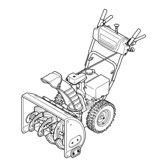
24" SNOW THROWER
Model No. 247.881731
CAUTION: Before using this
product, read this manual and
follow all safety rules and operating
instructions.
Sears Brands Management Corporation, Hoffman Estates, IL 60179, U.S.A.
®
Visit our website: www.craftsman.com
• SAFETY
• ASSEMBLY
• OPERATION
• MAINTENANCE
• PARTS LIST
• ESPAÑOL
Form No. 769-08174C
(June 21, 2013)
Advertisement
Chapters
Table of Contents

Subscribe to Our Youtube Channel
Related Manuals for Sears Craftsman 247.881731


Summary of Contents for Sears Craftsman 247.881731
- Page 1 CAUTION: Before using this • PARTS LIST product, read this manual and • ESPAÑOL follow all safety rules and operating instructions. Sears Brands Management Corporation, Hoffman Estates, IL 60179, U.S.A. Visit our website: www.craftsman.com Form No. 769-08174C (June 21, 2013)
-
Page 2: Table Of Contents
FOR AS LONG AS IT IS USED by the original owner after the second year from the date of purchase,the upper and lower chute of this snow thrower are warranted against any defects in material or workmanship as verified by a Sears authorized service provider. With proof of purchase, you will receive a new chute free of charge. - Page 3 SAFETY INSTRUCTIONS WARNING DANGER This symbol points out important safety instructions which, if not This machine was built to be operated according to the safe operation followed, could endanger the personal safety and/or property of practices in this manual. As with any type of power equipment, yourself and others.
- Page 4 SAFETY INSTRUCTIONS • To reduce fire hazards, keep machine free of grass, leaves, or other debris • Use only attachments and accessories approved by the manufacturer (e.g. build-up. Clean up oil or fuel spillage and remove any fuel soaked debris. wheel weights, tire chains, cabs etc.).
- Page 5 In the State of California the above is required by law (Section 4442 of the California Public Resources Code). Other states may have similar laws. Federal laws apply on federal lands. A spark arrestor for the muffler is available through your nearest Sears Parts and Repair Service Center.
- Page 6 SAFETY INSTRUCTIONS SAFETY SYMBOLS This page depicts and describes safety symbols that may appear on this product. Read, understand, and follow all instructions on the machine before attempting to assemble and operate. Symbol Description READ THE OPERATOR’S MANUAL(S) Read, understand, and follow all instructions in the manual(s) before attempting to assemble and operate WARNING—...
- Page 7 This page left intentionally blank.
-
Page 8: Assembly
ASSEMBLY NOTE: References to right or left side of the snow thrower are determined from behind the unit in the operating position (standing directly behind the snow thrower, facing the handle panel). Removing From Carton Cut the corners of the carton and lay the sides flat on the ground. Remove and discard all packing inserts. - Page 9 ASSEMBLY Place chute onto chute base and secure chute control head to chute support bracket with clevis pin and cotter pin removed earlier. See Figure 4. Finish securing chute control head to chute support bracket with wing nut and hex screw removed earlier. See Figure 5. Insert the chute directional control into the support bracket on the rear of the dash panel.
- Page 10 ASSEMBLY Set-Up Chute Clean-Out Tool A chute clean-out tool is fastened to the top of the auger housing with a mounting clip. See Figure 8. The tool is designed to clear a chute assembly of ice and snow. This item is fastened with a cable tie at the factory. Cut the cable tie before operating the snow thrower.
-
Page 11: Operation
OPERATION Chute The distance snow is thrown can be adjusted by changing the angle of the upper chute. To do so: Stop the engine by removing the ignition key and loosen the plastic wing knob found on the left side of the chute assembly. Pivot the chute upward or downward before retightening the wing knob. - Page 12 OPERATION Shift Lever Drive Control Auger Control Gas Cap Overhead Chute Directional Control Chute Assembly Clean Out Recoil Starter Tool Handle Primer Auger Housing Oil Fill Throttle Control Choke Control Electric Start Augers Button Skid Shoe Oil Drain Electric Starter Outlet Figure 12 Now that you have set up your snow thrower, it’s important to become acquainted with its controls and features.
- Page 13 OPERATION Throttle control Drive Control/ Auger Control Lock DRIVE CONTROL The throttle control is located on the rear of the engine. It regulates the speed of the engine and will shut off the engine when moved into the STOP position. Primer Depressing the primer forces fuel directly into the engine’s carburetor to aid in cold-weather starting.
- Page 14 OPERATION Clean-Out Tool • Do not overfill the fuel tank. After refueling, make sure the tank cap is closed properly and securely. WARNING • Be careful not to spill fuel when refueling. Spilled fuel or fuel vapor may ignite. If any fuel is spilled, make sure the area is dry before starting the Never use your hands to clear a clogged chute assembly.
- Page 15 CAUTION warm, place choke in RUN position. NEVER replace the auger shear pins with anything other than Sears SKU# Push primer three (3) times, making sure to cover vent hole when pushing. 88389/OEM Part No. 738-04124A replacement shear pins. Any damage to If engine is warm, push primer only once.
-
Page 16: Service &Maintenance
Use the Service Log column to keep track of completed Before performing any type of maintenance/service, disengage all controls maintenance tasks. To locate the nearest Sears Service Center or to schedule service, and stop the engine. Wait until all moving parts have come to a complete simply contact Sears at 1-800-4-MY-HOME®. - Page 17 SERVICE AND MAINTENANCE Refill with the recommended oil and check the oil level. See Recommended Oil Usage chart. The engine’s oil capacity is 20 ounces. Synthetic 0W-30 5W-30 -40º -20º 0º 20º 40º -30º -20º -10º 0º Oil Drain Plug CAUTION DO NOT use nondetergent oil or 2-stroke engine oil.
- Page 18 SERVICE AND MAINTENANCE Lubrication Gear Shaft The gear (hex) shaft should be lubricated at least once a season or after every 25 hours of operation. To prevent spillage, remove all fuel from tank by running engine until it stops. Carefully pivot the snow thrower up and forward so that it rests on the auger housing.
- Page 19 SERVICE AND MAINTENANCE Adjustments Shift Cable If the full range of speeds (forward and reverse) cannot be achieved, refer to the figure to the right and adjust the shift cable as follows: Place the shift lever in the fastest forward speed position (F6). Loosen the hex nut on the shift cable index bracket.
- Page 20 SERVICE AND MAINTENANCE Auger Control Refer to the Assembly section for instructions on adjusting the auger control cable. Skid Shoes Refer to the Assembly section for instructions on adjusting the skid shoes. Belt Replacement Auger Belt To remove and replace your snow thrower’s auger belt, proceed as follows: To prevent spillage, remove all fuel from tank by running engine until it stops.
- Page 21 Drive Belt NOTE: Several components must be removed and special tools are required in order to replace the snow thrower’s drive belt. Contact the nearest Sears Parts & Repair Center to have the drive belt replaced. Friction Wheel Removal...
- Page 22 SERVICE AND MAINTENANCE Carefully remove the hex nut and washer which secures the hex shaft to the snow thrower frame and lightly tap the shaft’s end to dislodge the ball bearing from the right side of the frame. See Figure 30. NOTE: Be careful not to damage the threads on the shaft.
-
Page 23: Off-Season Storage
OFF-SEASON STORAGE If the snow thrower will not be used for 30 days or longer, or if it is the end of the snow season when the last possibility of snow is gone, the equipment needs to be stored properly. Follow storage instructions below to ensure top performance from the snow thrower for many more years. Preparing Engine Preparing Snow Thrower Engines stored over 30 days need to be drained of fuel to prevent deterioration and... -
Page 24: Troubleshooting
Always wear safety glasses during operation or while performing any adjustments or repairs. This section addresses minor service issues. To locate the nearest Sears Service Center or to schedule service, simply contact Sears at 1-800-4-MY-HOME®. Problem... - Page 25 TROUBLESHOOTING Problem Cause Remedy Unit fails to discharge snow 1. Chute assembly clogged. 1. Stop engine immediately and disconnect spark plug wire. Clean chute assembly and inside of auger housing with clean-out tool or a stick. 2. Foreign object lodged in auger. 2.
-
Page 26: Parts List
PARTS LIST Craftsman Snow Thrower Model 247.881731 23 12... - Page 27 PARTS LIST Craftsman Snow Thrower Model 247.881731 Ref. Ref. Part No. Description Part No. Description 684-04265-4044 Housing Assembly, Auger 24” 731-2635 Snow Removal Tool Mount 684-04107-0637 Spiral Assembly, LH 684-04057A-0637 Impeller Assembly, 12” Dia. 684-04108-0637 Spiral Assembly, RH 710-0347 Hex Screw, 3/8-16, 1.75, Gr5 731-04870 Spacer, 1.25 OD x .75 ID x 1.00 710-0451...
- Page 28 PARTS LIST Craftsman Snow Thrower Model 247.881731 2 23 19 12...
- Page 29 Screw, Shoulder, .43 x 1.3, 1/4-20 747-05386-0637 Crank, Chute 684-04311A-0637 Bracket, Chute Support — 753-08018† Chute Kit (Incl. Ref.# 5 & 36) 946-04397A Cable, Speed Selector 749-04191A-0637 Handle, Upper, LH † Available for warranty coverage only. Contact a Sears authorized service provider for details.
- Page 30 PARTS LIST Craftsman Snow Thrower Model 247.881731...
- Page 31 PARTS LIST Craftsman Snow Thrower Model 247.881731 Ref. Ref. Part No. Description Part No. Description 738-04493 Axle, .75 x 22” 656-04055 Disc Assembly, Friction Wheel 936-0329 Washer, Lock, 1/4 684-04153C Friction Wheel Assembly, 5.5 OD 684-04154B-0637 Support Bracket, Friction Wheel 710-0809 Hex Screw, 1/4-20, 1.25, Gr5 710-0191...
- Page 32 PARTS LIST Craftsman Engine Model 270-SUA For Snow Model 247.881731 Ref. Part No. Description 951-11282 Muffler Assembly 710-05001 Muffler Stud 951-14190 Muffler Stud Kit 951-11289 Muffler Gasket 712-04214 Nut - M8 710-04915 Bolt - M6 X 12 Zin 951-10642B Muffler Shroud...
- Page 33 PARTS LIST Craftsman Engine Model 270-SUA For Snow Model 247.881731 Ref. Part No. Description 951-10634 Shroud-Engine 712-04213 951-11284 Choke Knob 951-10757 Throttle Knob 951-10637 Switch-Ignition 731-05632 Ignition Key Switch 951-10640 Push Rod-Choke 951-10635 Air Filter Heating 710-04943 Bolt-M6 1X28M Spec...
- Page 34 PARTS LIST Craftsman Engine Model 270-SUA For Snow Model 247.881731 131 - Gasket Kit-Complete 132 - Gasket Kit-External 133 - Complete Engine 77 78...
- Page 35 PARTS LIST Craftsman Engine Model 270-SUA For Snow Model 247.881731 Ref. Part No. Description 951-12111 Piston Ring Set 951-11632 Piston Pin Snap Ring 951-12007 Piston 951-11633 Piston Pin 710-04915 Bolt - M6 X 12 Zin 951-11113 Shield - Air 951-11573 Connecting Rod Assembly 951-14053 Governor Shaft...
- Page 36 PARTS LIST Craftsman Engine Model 270-SUA For Snow Model 247.881731 131 - Gasket Kit-Complete 132 -Gasket Kit-External 133 - Complete Engine...
- Page 37 PARTS LIST Craftsman Engine Model 270-SUA For Snow Model 247.881731 Ref. Part No. Description 710-04968 Flange Bolt M6 951-11054A Valve Cover 731-07059 Hose-Breather 726-04101 Clamp-Breather Hose 951-11565 Valve Cover Gasket 951-12000 Intake Valve Spring Retainer 951-11892 Rocker Arm Assembly 751-11124 Nut - Pivot Lockin 751-11123 Nut - Valve Adjust...
- Page 38 PARTS LIST Craftsman Engine Model 270-SUA For Snow Model 247.881731 134 - Carburetor Kit - Deni 135 - Carburetor Kit - Huayi...
- Page 39 PARTS LIST Craftsman Engine Model 270-SUA For Snow Model 247.881731 Ref. Part No. Description 710-04939 Stud-Carb 710-04910 Stud - M6 X 105 951-11567 Gasket-Carb Insulator 951-11896 Carburetor Insulat 951-11569A Carburetor Gasket 951-10639A Primer 951-11824 Primer Bulb 951-14026A Carburetor Assembly - Huayi 951-14027A Carburetor Assembly - Deni 951-11897...
- Page 40 PARTS LIST Craftsman Engine Model 270-SUA For Snow Model 247.881731 Ref. Part No. Description 951-10646 Ignition Coil 951-11110 Shield - Air Flow 710-04940 Bolt 710-04919 Bolt - Flange M6 951-12416 Flywheel 951-10934 Cooling Fan 951-10911 Starter Cup 712-04209 Nut - M14 710-04915 Bolt - M6 X 12 Zin 951-10663A...
- Page 41 PARTS LIST Craftsman Engine Model 270-SUA For Snow Model 247.881731 Ref. Part No. Description Ref. Part No. Description 951-11914 Engine/Dipstick Cover 951-10758 Throttle Control Assembly 710-04905 Bolt 710-05103 Bolt-M6 X 12 710-04915 Bolt - M6 X 12 Zin 951-11108 Shield - Governor 951-11913 Oil Fill Tube Assembly 951-11935...
- Page 42 PARTS LIST Craftsman Engine Model 270-SUA For Snow Model 247.881731 Ref. Part No. Description 710-04914 Bolt - Flange M6 951-11680 Flexible Clamp 951-11114 Bracket - Switch Housing Mount 712-05015 710-04965 Screw M4 X 55 710-04935 Screw - M4 X 60 710-05182 Bolt-M6 X 32 715-04088...
- Page 43 PARTS LIST Craftsman Snow Thrower Model 247.881731 777S32636 777X43688 777D18152 777S32236 777D16340 OVERHEAD VALVE 777I22363 777D16355 777I23031 777I23030 777D18044...
- Page 44 FEDERAL and/or CALIFORNIA EMISSION CONTROL WARRANTY STATEMENT YOUR WARRANTY RIGHTS AND OBLIGATIONS MTD Consumer Group Inc, the United States Environmental Protection Agency (EPA), and for those products certified for sale in the state of California, the California Air Resources Board (CARB) are pleased to explain the emission (evaporative and/or exhaust) control system (ECS) warranty on your 2013 and later small off-road spark-ignited engine and equipment (outdoor equipment engine).
- Page 45 Add-on or modified parts that are not exempted by the Air Resources Board may not be used. The use of any non-exempted add-on or modified parts by the ultimate purchaser will be grounds for disallowing a warranty claims. MTD Consumer Group Inc will not be liable to warrant failures of warranted parts caused by the use of a non-exempted add-on or modified part.
-
Page 46: Repair Protection Agreement
Discount of 25% from regular price of service and related installed parts not covered by the agreement; also, 25% off regular price of preventive maintenance check Fast help by phone – we call it Rapid Resolution – phone support from a Sears representative. Think of us as a “talking owner’s manual.”... -
Page 47: Declaración De Garantía
PARA SIEMPRE Y CUANDO SE UTILIZA por el propietario original después del segundo año desde la fecha de compra, el conducto superior e inferior de este quitanieves están garantizados contra cualquier defecto de materiales o mano de obra debe ser verificado por un proveedor de servicio autorizado Sears. Con el comprobante de compra, usted recibirá... -
Page 48: Prácticas Operación Seguras
INSTRUCCIONES DE SEGURIDAD ADVERTENCIA PELIGRO La presencia de este símbolo indica que se trata de instrucciones Esta máquina fue construida para ser operada de acuerdo con las reglas importantes de seguridad que se deben respetar para evitar poner en de seguridad contenidas en este manual. Al igual que con cualquier tipo peligro su seguridad personal y/o material y la de otras personas. - Page 49 INSTRUCCIONES DE SEGURIDAD Manejo seguro de la gasolina • Nunca opere la máquina si falta un montaje del canal o si el mismo está dañado. Mantenga todos los dispositivos de seguridad en su lugar y en Para evitar lesiones personales o daños materiales tenga mucho cuidado cuando funcionamiento.
- Page 50 INSTRUCCIONES DE SEGURIDAD • Para encender el motor, jale de la cuerda lentamente hasta que sienta • Según la Comisión de Seguridad de Productos para el Consumidor de los resistencia, luego jale rápidamente. El repliegue rápido de la cuerda de Estados Unidos (CPSC) y la Agencia de Protección Ambiental de los Estados arranque (tensión de retroceso) le jalará...
- Page 51 INSTRUCCIONES DE SEGURIDAD SÍMBOLOS DE SEGURIDAD Esta página describe los símbolos y figuras de seguridad internacionales que pueden aparecer en este producto. Lea el manual del operador para obtener la información terminada sobre seguridad, reunirse, operación y mantenimiento y reparación. Símbolo Descripción LEA EL MANUAL DEL OPERADOR (S)
-
Page 52: Montaje
MONTAJE NOTA: las referencias al lado derecho o y ciertos de la máquina quitanieve se determinan desde la parte posterior de la unidad en posición de operación (permaneciendo directamente detrás de la máquina quitanieve, mirando hacia el panel de la manija). Extracción de la Unidad de la Caja Corte las esquinas de la caja de cartón y extiéndala en el piso Quite y descarte todos los insertos de empaque. - Page 53 MONTAJE Lugar rampa hasta la base de la tolva y la cabeza seguro de control del canal de soporte del conducto con el apoyo de pasador de horquilla y pasador quitó antes. Ver Figura 4. Termine de asegurar la cabeza de control del canal de soporte del conducto de soporte con la tuerca de mariposa y el tornillo hexagonal retirados anteriormente.
- Page 54 MONTAJE Configuración Herramienta de Limpieza del Canal Hay una herramienta de limpieza del canal iajustada a la parte superior de la caja de la barrena con un pasador de ensamblado. Vea la Figura 8. La herramienta está diseñada para limpiar el hielo y la nieve del montaje de un canal. Este producto se sujeta mediante una unión de cable en la fábrica.
- Page 55 OPERACIÓN Canal Es posible ajustar la distancia a la cual se arroja la nieve cambiando el ángulo del canal superior. Para hacerlo: Detenga el motor quitando la llave de encendido y afloje la perilla a mariposa de plástico que se encuentra en el lado izquierdo del montaje del canal. Gire el canal hacia arriba o hacia abajo antes de apretar la perilla a mariposa.
-
Page 56: Operación
OPERACIÓN Control de Transmisión Palanca de Cambios Control de la Barrena Tapón de combustible Control direccional del canal Sobrecarga Montaje del canal Herramienta de Manija del arrancador limpieza del canal Silenciador de retroceso Cebador Caja de la barrena Llave Llenado aceite Control del regulador... - Page 57 OPERACIÓN Control del Regulador Control de la Transmisión/ Control de la Barrena de Cerradura CONTROL DE LA TRANSMISIÓN El control del regulador está ubicado en la parte trasera del motor. Regula la velocidad del motor, y lo apaga cuando se lo coloca en la posición STOP (detención). Cebador Al presionar el cebador se envía combustible directamente al carburador del motor para ayudar al...
- Page 58 OPERACIÓN Herramienta de Limpieza Gasolina Utilice gasolina para automóviles (sin plomo o con bajo contenido de plomo para ADVERTENCIA minimizar los depósitos en la cámara de combustión) con un octanaje mínimo de 87. Se puede usar gasolina con hasta un 10% de etanol o un 15% de MTBE (éter metílico Nunca use sus manos para liberar un montaje de canal tapado.
- Page 59 OPERACIÓN Arrancador Eléctrico Mueva la palanca de control del regulador a la posición FAST (rápido, representada por una liebre ADVERTENCIA Mueva la palanca del cebador hasta la posición CHOKE (encendido con El arrancador eléctrico está diseñado para operar con corriente el motor en frío).
-
Page 60: Servicio Y Mantenimiento
Para ubicar el Centro de todos los mandos y pare el motor. Espere hasta que todas las partes de Servicio Sears más cercano o para programar un servicio, simplemente comuníquese movimiento hayan venido a una parada completa. Desconecte el alambre con Sears al teléfono 1-800-4-MY-HOME®. - Page 61 El aceite usado es un residuo peligroso. Elimine el aceite usado adecuadamente. No lo arroje junto con los residuos domiciliarios. Consulte a las autoridades locales o al centro de servicio Sears para averiguar dónde hay instalaciones para la eliminación/ reciclaje segura(o) del aceite usado.
- Page 62 SERVICIO Y MANTENIMIENTO Mida la separación de bujía con un calibrador. Corrija de ser necesario torciendo el electrodo lateral. Vea la Figura 16. La separación debe establecerse entre 0,02 y 0,03 pulgadas (0,60-0,80 mm). Verifique que la arandela de la bujía esté en buenas condiciones y enrósquela Electrodo manualmente para no estropear la rosca.
- Page 63 SERVICIO Y MANTENIMIENTO Para retirar las zapatas antideslizantes: Quite los cuatro pernos del carro, arandelas, y las tuercas de brida hexagonales que los aseguran a la máquina quitanieve. Monte las nuevas zapatas antideslizantes con cuatros pernos de carro (dos en cada lado), arandelas, y las tuercas de brida hexagonales.
- Page 64 SERVICIO Y MANTENIMIENTO Tolva Si el conducto no se mantenga estacionario durante el funcionamiento, la carga previa de la tolva se puede ajustar apretando la tuerca hexagonal se encuentra en la parte frontal del cabezal de control tolva. Para incrementar la precarga, apretar la tuerca hexagonal en sentido horario en intervalos de ¼...
- Page 65 NOTA: Varios componentes deben ser retirados y se requieren herramientas especiales para reemplazar la correa de la máquina quitanieve unidad. Póngase en contacto con las piezas más cercana centro de servico Sears para que la correa de transmisión reemplazado. Figura 26...
- Page 66 SERVICIO Y MANTENIMIENTO Extracción de la Rueda de Fricción Si la máquina quitanieve no se acciona cuando el control de la transmisión está engranado, y si al realizar el ajuste del cable de control de la transmisión que aparece el problema no se corrige, tal vez se deba reemplazar la rueda de fricción. Siga las instrucciones que aparecen a continuación.
- Page 67 PRECAUCIÓN NUNCA cambie los pasadores de cuchilla de las barrenas por otra cosa que los pasadores de cuchilla de repuesto del fabricante de Sears, Nº de pieza 88389 Cualquier daño que sufra el engranaje de la barrena o cualquier otro componente por dejar de hacerlo lo anterior, NO estará cubierto por la garantía de su máquina quitanieve.
-
Page 68: Almacenamiento Fuera De Temporada
ALMACENAMIENTO FUERA DE TEMPORADA Si no se va a utiliza el equipo durante 30 días o más, o si es el final de la temporada de nieve y ya no existe posibilidad de que nieve, es necesario almacenar el equipo de manera adecuada. - Page 69 NOTAS...
-
Page 70: Solución De Problemas
Siempre lleve puestos cristales inastillables durante la operación o realizando cualquier ajuste o reparaciones. Esta sección se ocupa de cuestiones de menor importancia del servicio. Para localizar el más cercano Centro de Servicio Sears, o para programar un servicio, simplemente póngase en contacto con Sears al 1-800-4-MY-HOME ®. - Page 71 2. La correa de transmisión está floja o dañada. 2. Ha reemplazado la correa de transmisión. Contacte con su centro de partes y reparaciones Sears. 3. Rueda de fricción llevada puesta. 3. Ha reemplazado la rueda de fricción de piezas en un Centro de Servicio Sears.
- Page 72 DECLARACIÓN FEDERAL y/o DE CALIFORNIA SOBRE GARANTÍAS EN EL CONTROL DE EMISIONES SUS DERECHOS Y OBLIGACIONES EN CUANTO A LA GARANTÍA MTD Consumer Group Inc, la Agencia de Protección Medioambiental de los Estados Unidos (EPA), y para aquellos productos certificados para su venta en el estado de California, el Departamento de los Recursos del Aire de California (CARB) se complacen en explicar la garantía que cubre al sistema de control (ECS) de emisiones (evaporativas y/o de escape) de su equipo y motor (motor de equipos de exteriores) de encendido por chispa para todo terreno, pequeño, de exteriores del año 2013 y años posteriores En California, los nuevos motores de equipos de exteriores...
- Page 73 El propietario del motor de equipos de exteriores no deberá pagar el trabajo de diagnóstico directamente asociado con una pieza garantizada defectuosa en relación con las emisiones, siempre y cuando dicho trabajo de diagnóstico se realice en un centro cubierto por la garantía.
-
Page 74: Acuerdo De Protección Para Reparaciones
El *Coverage en Canadá varía en algunos artículos. Para detalles llenos la llamada Chamusca Canadá en 1-800- 361-6665. Servicio de instalación de Sears Si desea solicitar la instalación profesional de Sears de aparatos domésticos, dispositivos para abrir portones, calentadores de agua y otros artículos domésticos importantes, en los Estados Unidos o Canadá llame al 1-800-4-MY-HOME®. - Page 75 Esta página se marchó intencionadamente en blanco.
- Page 76 Trademark of KCD IP, LLC in the United States, or Sears Brands, LLC in other countries ® Marca Registrada / Marca de Fábrica de KCD IP, LLC en Estados Unidos, o Sears Brands, LLC in otros países Marque de commerce /...
Need help?
Do you have a question about the Craftsman 247.881731 and is the answer not in the manual?
Questions and answers