Table of Contents
Advertisement
Quick Links
Advertisement
Table of Contents

Related Manuals for Hunter HYDRAWISE HC-100-Flow-B m


Summary of Contents for Hunter HYDRAWISE HC-100-Flow-B m
- Page 1 HC Flow Meter HYDRAWISE-READY QUICK START GUIDE...
-
Page 2: Table Of Contents
Troubleshooting HC Support Thank you for purchasing the Hunter HC Flow Meter. In this Quick Start Guide, you will learn how to install and configure your flow meter. For support of Hydrawise™ cloud software or help with your Hydrawise account,... -
Page 3: Box Contents
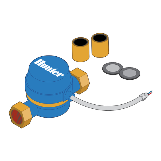
Box Contents ITEM QUANTITY Flow meter Gaskets Adapter fittings *Shielded direct-burial cable must be used for installation. Note: This product is intended for use with professional-grade materials. It must be installed by a licensed irrigation contractor or licensed electrician. -
Page 4: Hc Flow Meter
HC Flow Meter The flow meter consists of two parts: 1. Flow meter body: The flow meter body contains an analogue dial for manual readings as follows. Your flow meter will have 3 wires protruding from the body. The wires need to be connected to the sensor inputs on the controller for readings in the software application. -
Page 5: Planning
Planning Planning is an important step in the successful installation of your Hunter flow meter and the reliable operation of your irrigation system. 3. Flow meter location: Flow meters are installed between the master valve and zone valves. To avoid false alerts, there should be no water taps or other uncontrolled water use on the downstream side of the flow meter. -
Page 6: Max Length
Planning 4. Cable (shielded direct-burial cable must be used): Two-wire cable is required. The cable gauge is determined by the total length of cable between the controller and the flow meter. The cable should consist of 2 dedicated wires and must not be in the same conduit or cable bunch as the solenoid wires. Do not share the common wire of the solenoids with the common of the sensors. -
Page 7: Installing
Installing The following instructions assume you have already installed your Hydrawise controller. 1. Flow meter body: The flow meter has a marking on the body indicating the direction of water flow. Installation of the flow meter must be in the correct orientation with water flowing in the direction of the arrow on the flow meter body. - Page 8 Installing 2. Connect flow meter wire: Two-wire cable is required. The cable required to connect your flow meter must be dedicated to the flow meter and not shared with the common wire of the valves or other sensors. The cable gauge is determined by the total length of cable between the controller and the flow meter.
-
Page 9: Configuring
1 pulse per 10 litres 40 mm 40 mm flow meter 1 pulse per 10 litres 50 mm 50 mm flow meter 1 pulse per 10 litres 3. Assign zones to the flow sensor: Refer to hunter.direct/hchelp for app/software setup information. -
Page 10: Troubleshooting
Troubleshooting Need more helpful information on your product? Find tips on installation, controller programming, and more. hunter.direct/hchelp hydrawise.com/flowmeterinstall hunter.direct/winterization... - Page 11 Notes...
- Page 12 © 2019 Hunter Industries Inc. Hunter, the Hunter logo, and all other trademarks are property of Hunter Industries, registered in the U.S. and other countries. RESIDENTIAL & COMMERCIAL IRRIGATION Built on Innovation® Learn more. Visit hunterindustries.com LIT-694-QG-FlowMeter-EM B 4/19...
Need help?
Do you have a question about the HYDRAWISE HC-100-Flow-B m and is the answer not in the manual?
Questions and answers