Advertisement
Box Contents

| ITEM | QUANTITY |
| Flow meter | 1 |
| Gaskets | 2 |
| Adapter fittings | 2 |
*Shielded direct-burial cable must be used for installation.
 Note: This product is intended for use with professional-grade materials. It must be installed by a licensed irrigation contractor or licensed electrician.
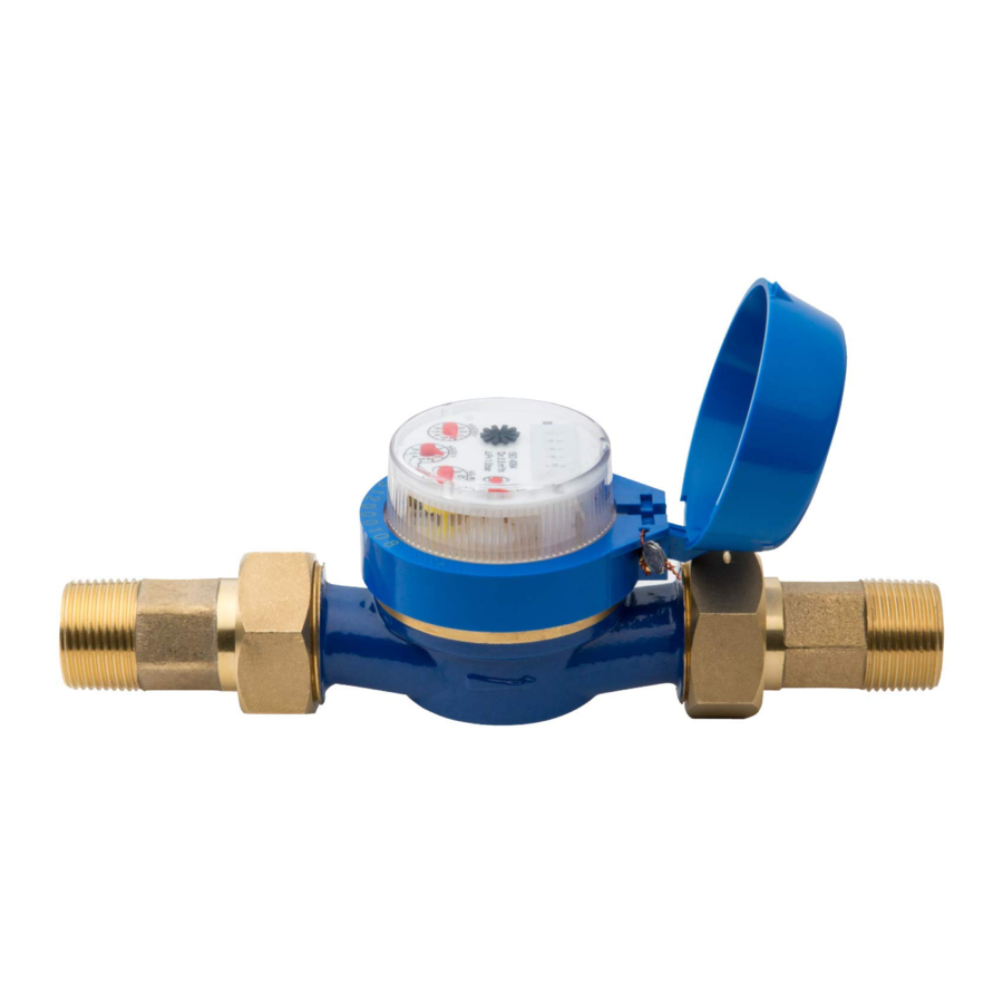
HC Flow Meters

The flow meter consists of two parts:
- Flow meter body: The flow meter body contains an analog dial for manual readings as follows. Your flow meter will have 3 wires protruding from the body. The wires need to be connected to the sensor inputs on the controller for readings in the software application. In all models, only 2 wires (blue and white) are used.
- Adapter: Each flow meter has an adapter to allow connection to your irrigation system.
Note: The flow meter displays U.S. gallons. If so desired, you can change the unit of measure in the app to liters.
| DIAL MARKING | MEASUREMENT UNIT |
| X0.01 | 0.1 gallon |
| X1 | 1 gallon |
| X10 | 10 gallons |
| X100 | 100 gallons |
Planning
Planning is an important step in the successful installation of your Hunter flow meter and the reliable operation of your irrigation system.
- Flow meter location: Flow meters are installed between the master valve and zone valves. To avoid false alerts, there should be no water taps or other uncontrolled water use on the downstream side of the flow meter. If all solenoids connected to the controller are not grouped together, it may be necessary to install more than one flow meter. For proper installation and optimal water flow, use the chart below when determining pipe length. The pipe bringing water into the flow meter needs to be 10 times longer than the width of the pipe. The pipe carrying water away from the meter needs to be 5 times the width of the pipe.
| PIPE | 10X-BEFORE | 5X-AFTER |
| 3/4" | 71/2" | 33/4" |
| 1" | 10" | 5" |
| 11/2" | 15" | 71/2" |
| 2" | 20" | 10" |
Note: Measurements in the chart are for minimum pipe length.
- Cable (shielded direct-burial cable must be used): Two-wire cable is required. The cable gauge is determined by the total length of cable between the controller and the flow meter. The cable should consist of 2 dedicated wires and must not be in the same conduit or cable bunch as the solenoid wires. Do not share the common wire of the solenoids with the common of the sensors.
Flow Meter Cable Length Chart
| WIRE SIZE | MAX LENGTH |
| Gauge | Feet |
| 20 | 240 |
| 18 | 1,000 |
Note: Shielded direct-burial cable is commonly available. Manufacturers include Paige Electric and Regency Wire.
Installing

The following instructions assume you have already installed your Hydrawise controller.
- Flow meter body: The flow meter has a marking on the body indicating the direction of water flow. Installation of the flow meter must be in the correct orientation with water flowing in the direction of the arrow on the flow meter body. All HC Flow Meters must be installed horizontally with the dial facing upward.
- Connect flow meter wire: Two-wire cable is required. The cable required to connect your flow meter must be dedicated to the flow meter and not shared with the common wire of the valves or other sensors. The cable gauge is determined by the total length of cable between the controller and the flow meter. The general rule is that 0.5 mm (20GA) wire is good for a run of up to 240'. Connect the wires to your Hydrawise controller.

| WIRE COLOR | SENSOR TERMINAL BLOCK |
| White | Common |
| Blue | Sen 1 or Sen 2 |
| Red | Not used: Wires should be capped with waterproof splice |
* Shield and bare wire should be connected to the controller ground terminal if available.
Note: All wire connections should be done using waterproof connectors, such as 3M 316IR or 3M DBY.
Configuring
Use your Hydrawise account to complete your flow meter configuration.
- Log in to your account: Enter your login information.
- Create a flow sensor: It is important that you select the correct flow meter when configuring your Hydrawise app. Choosing the wrong model may cause the Hydrawise controller to create false alerts in the software.
| HC FLOW METER SELECTION CHART | ||
| METER SIZE | DESCRIPTION | U.S. GALLON PULSE RATE |
| 3/ 4 " | 3/ 4 " flow meter | 1 pulse per 0.1 gallon |
| 1 | 1" flow meter | 1 pulse per 1 gallon |
| 1 1/2" | 11/ 2" flow meter | 1 pulse per 1 gallon |
| 2" | 2" flow meter | 1 pulse per 1 gallon |
- Assign zones to the flow sensor: Refer to hunter.direct/hchelp for app/software setup information.
Troubleshooting
Need more helpful information on your product? Find tips on installation, controller programming, and more.

 hunter.direct/hchelp

hydrawise.com/flowmeterinstall

hunter.direct/winterization
HC Support
Thank you for purchasing the Hunter HC Flow Meter. In this Quick Start Guide, you will learn how to install and configure your flow meter. For support of Hydrawise™ cloud software or help with your Hydrawise account, visit hunter.direct/hchelp. For specification information, refer to hunter.direct/hcflow.

Documents / Resources
References
Download manual
Here you can download full pdf version of manual, it may contain additional safety instructions, warranty information, FCC rules, etc.
Advertisement


Need help?
Do you have a question about the HC Flow Meter and is the answer not in the manual?
Questions and answers