Advertisement
Quick Links
Advertisement

Related Manuals for Hunter WVL-100-E


Summary of Contents for Hunter WVL-100-E
- Page 1 Wireless Valve Link INSTALLATION GUIDE WVL-100-E, -200-E, -400-E Wireless Valve Link (WVL)
- Page 2 Get the WVL App The Wireless Valve Link enables wire-free valve control and monitoring for new, existing, and add-on valves in ICC2 or HCC control systems. Get the WVL App to get started!
- Page 3 Installation Install the Wireless Valve Output Module in any output module slot in the controller and lock in place. The module lights will flash. Push the Reset button on the rear of the facepack.
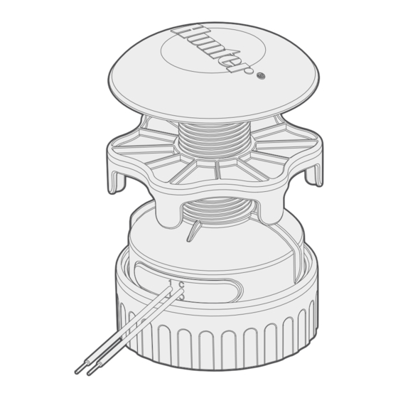
- Page 4 Installation Open the battery cover on the Wireless Valve Link. Unscrew the retaining ring, then remove the waterproof cover. Install one 9 V DC battery on the left side to allow easy access to the button on the right.
- Page 5 Installation Hold down the right button closest to wires for 2 seconds to enter assignment mode. The light will flash yellow. Connect the app to the Wireless Valve Output Module in the 3:25 PM controller. Use the app + button to assign the station numbers Back Add WVL 00352BBD and Save.
- Page 6 Installation Install a second 9 V DC battery. Write the station number on the Wireless Valve Link battery compartment. Reassemble the battery compartment. Push the cap down firmly. Make sure the O-rings are not misaligned and stay in their tracks. Then tighten the retaining ring (hand-tighten only).
- Page 7 Installation Take the Wireless Valve Link to the valve box and determine where it will be located. Make sure it won't interfere with the valve, or install in its own valve box. Final installation requires a minimum 4.25" (10.8 cm) diameter and 6.25"...
- Page 8 Installation Mark the location for the hole in the valve box lid. Use the hole saw supplied with the Wireless Valve Output Module to drill a 1.5" (38 cm) hole through the lid. A saw may be necessary to finish the cut through the lid’s support ribs. Insert the threaded column through the hole from the bottom, and secure with the cap above.
- Page 9 Installation Connect the numbered DC solenoid wires, red to red and black to black. Use only waterproof connectors. On multi-station versions, connect all black solenoid wires together with the black common from the Wireless Valve Link.
- Page 10 For complete operations and troubleshooting information, visit the Hunter Support pages. Hereby, Hunter Industries declares that the radio equipment type models WVL-100-E, WVL-200-E, and WVL-400-E is in compliance with Directive 2014/53/EU. The full text of the SCAN EU declaration of conformity is available at the following...
- Page 11 Notes...
- Page 12 Landscape Irrigation and Outdoor Lighting HUNTER INDUSTRIES | Built on Innovation ® © 2024 Hunter Industries Inc. Hunter, the Hunter logo, and other 1940 Diamond Street, San Marcos, CA 92078 USA marks are trademarks of Hunter Industries Inc., registered in the hunterindustries.com...
Need help?
Do you have a question about the WVL-100-E and is the answer not in the manual?
Questions and answers