Advertisement
Quick Links
www.ti.com
EVM User's Guide: TPS923650 TPS923651
TPS923651/0 65V 2A/1A Boost/Buck-Boost LED Driver
Evaluation Module with PWM/Analog Dimming
Description
The TPS923651/0 evaluation module (EVM) is a two-
layer PCB assembly with multiple variants to help the
user evaluate the main features and performance of
the TPS923651/0 device family. The TPS923651/0
is a 2A / 1A non-synchronous Boost / Buck-Boost
LED driver with 4.5V to 65V wide input range with
PWM / analog dimming function. By integrating the
low-side NMOS, the device is capable of driving
LEDs with high power density and high efficiency.
This document includes setup guidance, schematics,
printed-circuit board (PCB) layouts, and bill of
materials (BOM) for the whole family of TPS923651/0
EVMs, including TPS923651D1DSGREVM,
TPS923651D2DSGREVM,
TPS923650D1DSGREVM,
TPS923650D2DSGREVM,
TPS923651D1DGNREVM,
TPS923651D2DGNREVM,
TPS923650D1DGNREVM,
TPS923650D2DGNREVM, TPS923650D1DRLREVM
and TPS923650D2DRLREVM.
Features
•
LED common cathode connection
•
Integrated 300mΩ MOSFET
SLUUD69 – DECEMBER 2024
Submit Document Feedback
– Typical current limit (1.6A / 3.2A)
– Switching frequency (400kHz / 1MHz)
•
Advanced dimming options:
– D1 for PWM dimming
– D2 for Analog dimming
•
Full protection features:
– LED open and short protection
– Switching FET open and short protection
– External component failure protection
– Cycle-by-cycle current limit
– Thermal shutdown
•
Package: WSON-8, HVSSOP-8, SOT583
Applications
•
Constant illumination:
– Indoor and outdoor lighting
– Appliance lighting
– Cold/warm WLED lighting
– Emergency and signage lighting
– Security floodlight
– LED bulb and lamp
– LCD backlight
•
Instant illumination
– Machine vision and camera flash
– Fire alarm and strobe
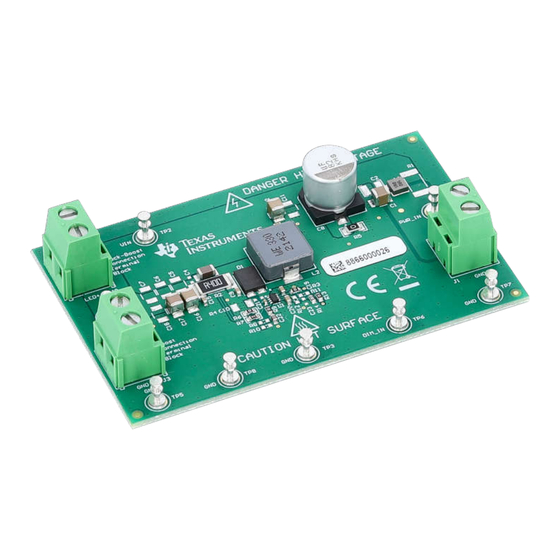
Figure 1-1. TPS923650D2DRLREVM
TPS923651/0 65V 2A/1A Boost/Buck-Boost LED Driver Evaluation Module
Copyright © 2024 Texas Instruments Incorporated
Description
1
with PWM/Analog Dimming
Advertisement

Subscribe to Our Youtube Channel
Related Manuals for Texas Instruments TPS923650


Summary of Contents for Texas Instruments TPS923650
- Page 1 Description EVM User's Guide: TPS923650 TPS923651 TPS923651/0 65V 2A/1A Boost/Buck-Boost LED Driver Evaluation Module with PWM/Analog Dimming – Typical current limit (1.6A / 3.2A) Description – Switching frequency (400kHz / 1MHz) The TPS923651/0 evaluation module (EVM) is a two- •...
- Page 2 Read the user's guide before use. CAUTION Hot surface. Contact can cause Caution burns. Do not touch! TPS923651/0 65V 2A/1A Boost/Buck-Boost LED Driver Evaluation Module SLUUD69 – DECEMBER 2024 with PWM/Analog Dimming Submit Document Feedback Copyright © 2024 Texas Instruments Incorporated...
- Page 3 Units Output Current All TPS923651 EVM (For D1 version, DIM = 3.3VDC. For D2 version, DIM = 2VDC) All TPS923650 EVM (For D1 version, DIM = 3.3VDC. For D2 version, DIM = 2VDC) Input Current All TPS923651 EVM (For D1 version, DIM = 3.3VDC.
- Page 4 The TPS923651/0 also provides multiple systematic protections, including LED open and short, switching FET open and short, sense resistor open and short, and thermal shutdown. TPS923651/0 65V 2A/1A Boost/Buck-Boost LED Driver Evaluation Module SLUUD69 – DECEMBER 2024 with PWM/Analog Dimming Submit Document Feedback Copyright © 2024 Texas Instruments Incorporated...
- Page 5 Limitation for Safe Use: – EVMs are not to be used as all or part of a production unit. SLUUD69 – DECEMBER 2024 TPS923651/0 65V 2A/1A Boost/Buck-Boost LED Driver Evaluation Module Submit Document Feedback with PWM/Analog Dimming Copyright © 2024 Texas Instruments Incorporated...
- Page 6 For safety, use of isolated test equipment with overvoltage and overcurrent protection is highly recommended. TPS923651/0 65V 2A/1A Boost/Buck-Boost LED Driver Evaluation Module SLUUD69 – DECEMBER 2024 with PWM/Analog Dimming Submit Document Feedback Copyright © 2024 Texas Instruments Incorporated...
- Page 7 • LED load with cables – It should be able to carry 1A continuous current for TPS923651 EVM. – It should be able to carry 0.5A continuous current for TPS923650 EVM. • Function generator with cables – It should be set to PWM mode for D1 version EVM.
- Page 8 Power Supply Load Func o n Generator ¡ Figure 2-2. Connection Diagram of TPS923650D1DRLREVM in Boost Connection TPS923651/0 65V 2A/1A Boost/Buck-Boost LED Driver Evaluation Module SLUUD69 – DECEMBER 2024 with PWM/Analog Dimming Submit Document Feedback Copyright © 2024 Texas Instruments Incorporated...
- Page 9 Figure 2-4. Connection Diagram of TPS923650D1DRLREVM in Buck-Boost Connection 2.3 Power Connections Table 2-1 describes the terminal blocks on the EVM for power connections. SLUUD69 – DECEMBER 2024 TPS923651/0 65V 2A/1A Boost/Buck-Boost LED Driver Evaluation Module Submit Document Feedback with PWM/Analog Dimming Copyright © 2024 Texas Instruments Incorporated...
- Page 10 Test point to apply positive DIM input signal Negative power input test point (GND) GND test point TPS923651/0 65V 2A/1A Boost/Buck-Boost LED Driver Evaluation Module SLUUD69 – DECEMBER 2024 with PWM/Analog Dimming Submit Document Feedback Copyright © 2024 Texas Instruments Incorporated...
- Page 11 Figure 3-1. LED current and SW waveform of TPS923650D2DRLREVM when DIM voltage transitions from 1VDC to 2VDC SLUUD69 – DECEMBER 2024 TPS923651/0 65V 2A/1A Boost/Buck-Boost LED Driver Evaluation Module Submit Document Feedback with PWM/Analog Dimming Copyright © 2024 Texas Instruments Incorporated...
- Page 12 10.0M 10.0M 0.015uF VI N-IC 200k 1502-2 DIM_INPUT 100nF 1502-2 1502-2 Figure 4-2. Schematic of LED039 TPS923651/0 65V 2A/1A Boost/Buck-Boost LED Driver Evaluation Module SLUUD69 – DECEMBER 2024 with PWM/Analog Dimming Submit Document Feedback Copyright © 2024 Texas Instruments Incorporated...
- Page 13 The PCB layout of LED037 (WSON package) is shown below. Figure 4-3. LED037 Top Layer Figure 4-4. LED037 Bottom Layer SLUUD69 – DECEMBER 2024 TPS923651/0 65V 2A/1A Boost/Buck-Boost LED Driver Evaluation Module Submit Document Feedback with PWM/Analog Dimming Copyright © 2024 Texas Instruments Incorporated...
- Page 14 The PCB layout of LED038 (HVSSOP package) is shown below. Figure 4-5. LED038 Top Layer Figure 4-6. LED038 Bottom Layer TPS923651/0 65V 2A/1A Boost/Buck-Boost LED Driver Evaluation Module SLUUD69 – DECEMBER 2024 with PWM/Analog Dimming Submit Document Feedback Copyright © 2024 Texas Instruments Incorporated...
- Page 15 The PCB layout of LED039 (SOT583 package) is shown below. Figure 4-7. LED039 Top Layer Figure 4-8. LED039 Bottom Layer SLUUD69 – DECEMBER 2024 TPS923651/0 65V 2A/1A Boost/Buck-Boost LED Driver Evaluation Module Submit Document Feedback with PWM/Analog Dimming Copyright © 2024 Texas Instruments Incorporated...
- Page 16 Capacitor X7S 1210 (3225 Metric) CAP, CERM, 0.1 uF, 100 V, +/- GRM32NR72A104KA01L MuRata 10%, X7R, 1210 TPS923651/0 65V 2A/1A Boost/Buck-Boost LED Driver Evaluation Module SLUUD69 – DECEMBER 2024 with PWM/Analog Dimming Submit Document Feedback Copyright © 2024 Texas Instruments Incorporated...
- Page 17 Resistor, 400mΩ ±1% 1W Chip 2512 CRG2512-FZ-R400E-1 Bourns All TPS923650 EVM (6432 Metric) Anti-Sulfur, Automotive AEC-Q200, Current Sense Metal Element SLUUD69 – DECEMBER 2024 TPS923651/0 65V 2A/1A Boost/Buck-Boost LED Driver Evaluation Module Submit Document Feedback with PWM/Analog Dimming Copyright © 2024 Texas Instruments Incorporated...
- Page 18 Power Inductor WE-MAPI SMT , size 74438334010 Wurth Elektronik All TPS923650 EVM 3012, 1μH, 2.75A, 50.5mΩ TPS923651/0 65V 2A/1A Boost/Buck-Boost LED Driver Evaluation Module SLUUD69 – DECEMBER 2024 with PWM/Analog Dimming Submit Document Feedback Copyright © 2024 Texas Instruments Incorporated...
- Page 19 Compliance Information 5 Compliance Information 5.1 Compliance and Certifications • TPS923650D2DRLREVM EU Declaration of Conformity (DoC) SLUUD69 – DECEMBER 2024 TPS923651/0 65V 2A/1A Boost/Buck-Boost LED Driver Evaluation Module Submit Document Feedback with PWM/Analog Dimming Copyright © 2024 Texas Instruments Incorporated...
- Page 20 Additional Information www.ti.com 6 Additional Information 6.1 Trademarks All trademarks are the property of their respective owners. TPS923651/0 65V 2A/1A Boost/Buck-Boost LED Driver Evaluation Module SLUUD69 – DECEMBER 2024 with PWM/Analog Dimming Submit Document Feedback Copyright © 2024 Texas Instruments Incorporated...
- Page 21 Related Documentation 7 Related Documentation • TPS923650/1 65V 1A/2A Boost/Buck-Boost LED Driver with PWM/Analog Dimming datasheet SLUUD69 – DECEMBER 2024 TPS923651/0 65V 2A/1A Boost/Buck-Boost LED Driver Evaluation Module Submit Document Feedback with PWM/Analog Dimming Copyright © 2024 Texas Instruments Incorporated...
- Page 22 STANDARD TERMS FOR EVALUATION MODULES Delivery: TI delivers TI evaluation boards, kits, or modules, including any accompanying demonstration software, components, and/or documentation which may be provided together or separately (collectively, an “EVM” or “EVMs”) to the User (“User”) in accordance with the terms set forth herein.
- Page 23 www.ti.com Regulatory Notices: 3.1 United States 3.1.1 Notice applicable to EVMs not FCC-Approved: FCC NOTICE: This kit is designed to allow product developers to evaluate electronic components, circuitry, or software associated with the kit to determine whether to incorporate such items in a finished product and software developers to write software applications for use with the end product.
- Page 24 www.ti.com Concernant les EVMs avec antennes détachables Conformément à la réglementation d'Industrie Canada, le présent émetteur radio peut fonctionner avec une antenne d'un type et d'un gain maximal (ou inférieur) approuvé pour l'émetteur par Industrie Canada. Dans le but de réduire les risques de brouillage radioélectrique à...
- Page 25 www.ti.com EVM Use Restrictions and Warnings: 4.1 EVMS ARE NOT FOR USE IN FUNCTIONAL SAFETY AND/OR SAFETY CRITICAL EVALUATIONS, INCLUDING BUT NOT LIMITED TO EVALUATIONS OF LIFE SUPPORT APPLICATIONS. 4.2 User must read and apply the user guide and other available documentation provided by TI regarding the EVM prior to handling or using the EVM, including without limitation any warning or restriction notices.
- Page 26 Notwithstanding the foregoing, any judgment may be enforced in any United States or foreign court, and TI may seek injunctive relief in any United States or foreign court. Mailing Address: Texas Instruments, Post Office Box 655303, Dallas, Texas 75265 Copyright © 2023, Texas Instruments Incorporated...
- Page 27 TI products. TI’s provision of these resources does not expand or otherwise alter TI’s applicable warranties or warranty disclaimers for TI products. TI objects to and rejects any additional or different terms you may have proposed. IMPORTANT NOTICE Mailing Address: Texas Instruments, Post Office Box 655303, Dallas, Texas 75265 Copyright © 2024, Texas Instruments Incorporated...
Need help?
Do you have a question about the TPS923650 and is the answer not in the manual?
Questions and answers