Table of Contents
Advertisement
Quick Links
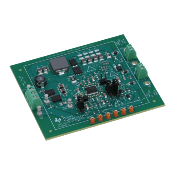
TPS92692 Boost and Boost-to-Battery LED Driver
This user's guide describes the characteristics, operation, and use of the TPS92692 Boost and Boost-to-
Battery Evaluation Module (EVM). A complete schematic diagram, printed-circuit board layouts, and bill of
materials are included in this document.
...................................................................................................................
1
....................................................................................................................
2
2.1
2.2
3
3.1
3.2
3.3
3.4
3.5
3.6
3.7
3.8
3.9
3.10
4
5
6
6.1
6.2
6.3
6.4
6.5
6.6
6.7
6.8
.................................................................................................................
6.9
7
8
9
9.1
9.2
9.3
9.4
10
11
1
2
This datasheet has been downloaded from
................................................................................................
..............................................................................................................
.......................................................................................................
........................................................................................
...............................................................................................
............................................................................................
.....................................................................................
......................................................................................................
...........................................................................................................
............................................................................................................
...........................................................................................................
...............................................................................................
.............................................................................................................
.....................................................................................................
...................................................................................................
.....................................................................................
............................................................................................
........................................................................................
..................................................................................
................................................................................................
.......................................................................................
...........................................................................................................
....................................................................................................
...................................................................................................
................................................................................................
.............................................................................................................
List of Figures
.........................................................................................................
Evaluation Board
Contents
......................................................................
.............................................................
...............................................................
..................................................................
......................................................
.................................................................
.............................................................
................................................
http://www.digchip.com
User's Guide
SLVUB29 - March 2017
at this
page
3
3
3
3
4
4
4
5
5
5
5
5
6
6
6
6
7
8
8
9
10
11
11
11
12
12
14
15
16
17
17
17
18
18
19
21
4
7
1
Advertisement
Table of Contents

Subscribe to Our Youtube Channel
Related Manuals for Texas Instruments TPS92692


Summary of Contents for Texas Instruments TPS92692
-
Page 1: Table Of Contents
TPS92692 Boost and Boost-to-Battery LED Driver Evaluation Board This user's guide describes the characteristics, operation, and use of the TPS92692 Boost and Boost-to- Battery Evaluation Module (EVM). A complete schematic diagram, printed-circuit board layouts, and bill of materials are included in this document. - Page 2 TPS92692EVM-880 Buck-Boost Configuration Electrical Performance Specifications ......................Bill of Materials Trademarks All trademarks are the property of their respective owners. TPS92692 Boost and Boost-to-Battery LED Driver Evaluation Board SLVUB29 – March 2017 Submit Documentation Feedback Copyright © 2017, Texas Instruments Incorporated...
-
Page 3: Introduction
(IMON) output. The device also includes an open-drain fault indicator output that indicates LED overcurrent, output overvoltage, and output undervoltage conditions. Typical Applications This converter design describes an application of the TPS92692-Q1 device as a Boost and Boost-to- Battery LED driver with the specifications described in Table 1. -
Page 4: Connector Description
Boost-to-Battery (Buck-Boost) configuration. The positive terminal for the LED load connects to LED+ while the negative terminal connects to VIN. The Boost-to-Battery design is for approximately 1 to 11 white LEDs. TPS92692 Boost and Boost-to-Battery LED Driver Evaluation Board SLVUB29 – March 2017 Submit Documentation Feedback... -
Page 5: J4, Fault Response Setting
TP2, Soft Start The test point SS connects through a 1-kΩ resistor to the SS pin of the TPS92692-Q1 device. The voltage range is from 0 V to 5 V, if driven externally. The SS voltage can be monitored with this test point. Pulling SS to GND will also serve to disable the part and put it into STANDBY mode. -
Page 6: Tp8, Pwm
Connector Description www.ti.com TP8, PWM The PWM test point connects through J7 to the DIM/PWM pin of the TPS92692-Q1 device. An analog voltage or PWM signal can be applied to set the LED current duty cycle based on the dimming configuration. -
Page 7: Boost Led Driver Schematic
33.0k 249k 0.1 µF 0.01 µF VBAT2 10.0k 10.0k Figure 2. TPS92692EVM-880 Schematic: Configured as a Boost LED Driver SLVUB29 – March 2017 TPS92692 Boost and Boost-to-Battery LED Driver Evaluation Board Submit Documentation Feedback Copyright © 2017, Texas Instruments Incorporated... -
Page 8: Performance Data And Typical Characteristic Curves
100 mA 300 mA Input Voltage (V) D003 Figure 5. Efficiency vs Input Voltage (Number of Series-Connected LEDs = 18) TPS92692 Boost and Boost-to-Battery LED Driver Evaluation Board SLVUB29 – March 2017 Submit Documentation Feedback Copyright © 2017, Texas Instruments Incorporated... -
Page 9: Line Regulation
13 LEDs Input Voltage (V) D006 Figure 8. Output LED Current vs Input Voltage (V = 2.1 V) IADJ SLVUB29 – March 2017 TPS92692 Boost and Boost-to-Battery LED Driver Evaluation Board Submit Documentation Feedback Copyright © 2017, Texas Instruments Incorporated... -
Page 10: Load Regulation
No. of Series Connected LEDs D009 Figure 11. Output LED Current vs LED String Configuration (V = 2.1 V) IADJ TPS92692 Boost and Boost-to-Battery LED Driver Evaluation Board SLVUB29 – March 2017 Submit Documentation Feedback Copyright © 2017, Texas Instruments Incorporated... -
Page 11: Temperature Characteristics
1 and 2 of J7. The DIM/PWM voltage and hence the LED current duty cycle is modulated based on the voltage supplied by the external DC power supply. SLVUB29 – March 2017 TPS92692 Boost and Boost-to-Battery LED Driver Evaluation Board Submit Documentation Feedback Copyright © 2017, Texas Instruments Incorporated... -
Page 12: Direct External Pwm Dimming
LED current; Time: 400 µs/div spaCh4: LED current; Time: 1 µs/div Figure 14. Normal Operation Figure 15. Spread Spectrum Frequency Modulation TPS92692 Boost and Boost-to-Battery LED Driver Evaluation Board SLVUB29 – March 2017 Submit Documentation Feedback Copyright © 2017, Texas Instruments Incorporated... -
Page 13: Startup Transient
LED current; Time: 100 ms/div spaCh4: LED current; Time: 100 ms/div Figure 20. LED Open-Circuit Fault Figure 21. LED Short-Circuit Fault SLVUB29 – March 2017 TPS92692 Boost and Boost-to-Battery LED Driver Evaluation Board Submit Documentation Feedback Copyright © 2017, Texas Instruments Incorporated... -
Page 14: Emi
Performance Data and Typical Characteristic Curves www.ti.com Figure 22. Conducted EMI Based on CISPR 25 Class 3 Limits (Dither Modulation Enabled) TPS92692 Boost and Boost-to-Battery LED Driver Evaluation Board SLVUB29 – March 2017 Submit Documentation Feedback Copyright © 2017, Texas Instruments Incorporated... -
Page 15: Buck-Boost Led Driver Electrical Performance Specifications
1 kHz Systems Characteristics Output overvoltage protection threshold Output overvoltage protection hysteresis Soft-start period Dither modulation frequency Switching frequency SLVUB29 – March 2017 TPS92692 Boost and Boost-to-Battery LED Driver Evaluation Board Submit Documentation Feedback Copyright © 2017, Texas Instruments Incorporated... -
Page 16: Buck-Boost Led Driver Schematic
33.0k 249k 0.1 µF 0.01 µF VBAT2 10.0k 10.0k Figure 23. TPS92692EVM-880 Schematic: Configured as a Buck-Boost LED Driver TPS92692 Boost and Boost-to-Battery LED Driver Evaluation Board SLVUB29 – March 2017 Submit Documentation Feedback Copyright © 2017, Texas Instruments Incorporated... -
Page 17: Performance Data And Typical Characteristic Curves
296.5 295.5 Input Voltage (V) D013 Figure 25. Output LED Current vs Input Voltage (V = 1.26 V) IADJ SLVUB29 – March 2017 TPS92692 Boost and Boost-to-Battery LED Driver Evaluation Board Submit Documentation Feedback Copyright © 2017, Texas Instruments Incorporated... -
Page 18: Load Regulation
LED current; Time: 100 ms/div spaCh4: LED current; Time: 100 ms/div Figure 27. LED Short-Circuit Fault Figure 28. LED Open-Circuit Fault TPS92692 Boost and Boost-to-Battery LED Driver Evaluation Board SLVUB29 – March 2017 Submit Documentation Feedback Copyright © 2017, Texas Instruments Incorporated... -
Page 19: Tps92692Evm-880 Assembly Drawing And Pcb Layout
TPS92692EVM-880 printed- circuit board. Figure 29. Assembly Drawing Figure 30. Top Layer and Top Overlay (Top View) SLVUB29 – March 2017 TPS92692 Boost and Boost-to-Battery LED Driver Evaluation Board Submit Documentation Feedback Copyright © 2017, Texas Instruments Incorporated... - Page 20 TPS92692EVM-880 Assembly Drawing and PCB layout www.ti.com Figure 31. Bottom Layer and Bottom Overlay (Bottom View) TPS92692 Boost and Boost-to-Battery LED Driver Evaluation Board SLVUB29 – March 2017 Submit Documentation Feedback Copyright © 2017, Texas Instruments Incorporated...
-
Page 21: Bill Of Materials
MI1206K601R-10 Laird-Signal Integrity Products 600 ohm Ferrite Bead, 600 ohm @ 100 MHz, 1.3 A, 0603 0603 BLM18KG601SN1D Murata SLVUB29 – March 2017 TPS92692 Boost and Boost-to-Battery LED Driver Evaluation Board Submit Documentation Feedback Copyright © 2017, Texas Instruments Incorporated... - Page 22 RES, 33.0 k, 1%, 0.1 W, 0603 0603 CRCW060333K0FKEA Vishay-Dale 249k RES, 249 k, 1%, 0.1 W, 0603 0603 CRCW0603249KFKEA Vishay-Dale TPS92692 Boost and Boost-to-Battery LED Driver Evaluation Board SLVUB29 – March 2017 Submit Documentation Feedback Copyright © 2017, Texas Instruments Incorporated...
- Page 23 STANDARD TERMS FOR EVALUATION MODULES Delivery: TI delivers TI evaluation boards, kits, or modules, including any accompanying demonstration software, components, and/or documentation which may be provided together or separately (collectively, an “EVM” or “EVMs”) to the User (“User”) in accordance with the terms set forth herein.
- Page 24 FCC Interference Statement for Class B EVM devices NOTE: This equipment has been tested and found to comply with the limits for a Class B digital device, pursuant to part 15 of the FCC Rules. These limits are designed to provide reasonable protection against harmful interference in a residential installation.
- Page 25 【無線電波を送信する製品の開発キットをお使いになる際の注意事項】 開発キットの中には技術基準適合証明を受けて いないものがあります。 技術適合証明を受けていないもののご使用に際しては、電波法遵守のため、以下のいずれかの 措置を取っていただく必要がありますのでご注意ください。 1. 電波法施行規則第6条第1項第1号に基づく平成18年3月28日総務省告示第173号で定められた電波暗室等の試験設備でご使用 いただく。 2. 実験局の免許を取得後ご使用いただく。 3. 技術基準適合証明を取得後ご使用いただく。 なお、本製品は、上記の「ご使用にあたっての注意」を譲渡先、移転先に通知しない限り、譲渡、移転できないものとします。 上記を遵守頂けない場合は、電波法の罰則が適用される可能性があることをご留意ください。 日本テキサス・イ ンスツルメンツ株式会社 東京都新宿区西新宿6丁目24番1号 西新宿三井ビル 3.3.3 Notice for EVMs for Power Line Communication: Please see http://www.tij.co.jp/lsds/ti_ja/general/eStore/notice_02.page 電力線搬送波通信についての開発キットをお使いになる際の注意事項については、次のところをご覧ください。http:/ /www.tij.co.jp/lsds/ti_ja/general/eStore/notice_02.page 3.4 European Union 3.4.1 For EVMs subject to EU Directive 2014/30/EU (Electromagnetic Compatibility Directive): This is a class A product intended for use in environments other than domestic environments that are connected to a low-voltage power-supply network that supplies buildings used for domestic purposes.
-
Page 26: Copyright © 2017, Texas Instruments Incorporated
Notwithstanding the foregoing, any judgment may be enforced in any United States or foreign court, and TI may seek injunctive relief in any United States or foreign court. Mailing Address: Texas Instruments, Post Office Box 655303, Dallas, Texas 75265 Copyright © 2017, Texas Instruments Incorporated... - Page 27 IMPORTANT NOTICE FOR TI DESIGN INFORMATION AND RESOURCES Texas Instruments Incorporated (‘TI”) technical, application or other design advice, services or information, including, but not limited to, reference designs and materials relating to evaluation modules, (collectively, “TI Resources”) are intended to assist designers who are developing applications that incorporate TI products;...
Need help?
Do you have a question about the TPS92692 and is the answer not in the manual?
Questions and answers