
Subscribe to Our Youtube Channel
Related Manuals for Texas Instruments TPS92520-Q1


Summary of Contents for Texas Instruments TPS92520-Q1
- Page 1 Advance Information TPS92520-Q1 LaunchPad-Controlled, ECU Evaluation Module User's Guide User's Guide Literature Number: SLUUC29B August 2019 – Revised October 2019...
-
Page 2: Table Of Contents
Programming the MSP-EXP432E401Y LaunchPad Board ................TPS92520EVM-074 Power UP and Operation ................. Launch the GUI (Graphical User Interface) ........................... Appendix .......................... Revision History Table of Contents SLUUC29B – August 2019 – Revised October 2019 Submit Documentation Feedback Copyright © 2019, Texas Instruments Incorporated... - Page 3 GUI Splash Screen with Configuration Information ......... GUI, Main Window (Numbered areas are for explanation purposes only) ....................SPI Command Window ................TPS92663EVM6-901 Addressing Outline SLUUC29B – August 2019 – Revised October 2019 List of Figures Submit Documentation Feedback Copyright © 2019, Texas Instruments Incorporated...
- Page 4 Advance Information www.ti.com List of Tables ....................Connector Descriptions ............TPS92520EVM-074 ECU EVM Performance Specifications ..................TPS92520EVM-074 Bill of Materials List of Tables SLUUC29B – August 2019 – Revised October 2019 Submit Documentation Feedback Copyright © 2019, Texas Instruments Incorporated...
- Page 5 Any other use and/or application are strictly prohibited by Texas Instruments. If you are not suitable qualified, you should immediately stop from further use of the HV EVM.
- Page 6 EVM in an adequate lucent plastic box with interlocks from accidental touch. Limitation for safe use: EVMs are not to be used as all or part of a production unit. List of Tables SLUUC29B – August 2019 – Revised October 2019 Submit Documentation Feedback Copyright © 2019, Texas Instruments Incorporated...
- Page 7 LEDs. The EVM is a representative of a lighting module suitable for automotive applications creating advanced lighting features. The TPS92520-Q1 buck current regulator device implements an adjustable constant on-time, valley detect, current-mode control technique with programmable pseudo-fixed-frequency operation. Additional features include the following: •...
-
Page 8: Trademarks
Advance Information www.ti.com Trademarks SimpleLink, LaunchPad are trademarks of Texas Instruments. All other trademarks are the property of their respective owners. TPS92520EVM-074 LaunchPad-Controlled, ECU Evaluation Module SLUUC29B – August 2019 – Revised October 2019 Submit Documentation Feedback Copyright © 2019, Texas Instruments Incorporated... -
Page 9: Description
Figure 1. TPS92520EVM-074 Block Diagram Typical Applications This document outlines the operation and implementation of the TPS92520-Q1 as a four-channel LED current regulator. Table 2 lists the specifications. For applications with a different input voltage range or... -
Page 10: Connector Description
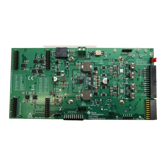
TPS92520EVM-074. Figure 2 shows the connection diagram and the jumper locations of the TPS92520EVM-074. Figure 2. Component Connections TPS92520EVM-074 LaunchPad-Controlled, ECU Evaluation Module SLUUC29B – August 2019 – Revised October 2019 Submit Documentation Feedback Copyright © 2019, Texas Instruments Incorporated... -
Page 11: Jumper Placement For Launch Pad Use
Dual-Phase VC Boost Output. Adjust R34 to set the maximum boost output VBOOST Boost Output voltage. Ground Ground test points SLUUC29B – August 2019 – Revised October 2019 TPS92520EVM-074 LaunchPad-Controlled, ECU Evaluation Module Submit Documentation Feedback Copyright © 2019, Texas Instruments Incorporated... -
Page 12: Reach Compliance
EU REACH regulation, TI is notifying you that this EVM includes component or components that contain at least one substance of very high concern (SVHC) above 0.1%. These uses from Texas Instruments do not exceed one ton per year. The SVHC specifications are:... -
Page 13: Performance Data And Typical Characteristic Curves
, COMP, and the switch-node voltage (SWN). In this setup, a string of 7×LEDs are connected to the buck output and the boost is set to 47 V. SLUUC29B – August 2019 – Revised October 2019 TPS92520EVM-074 LaunchPad-Controlled, ECU Evaluation Module Submit Documentation Feedback Copyright © 2019, Texas Instruments Incorporated... -
Page 14: Pwm Dimming
This section contains TPS92520EVM-074 schematics, PCB layouts, and bill of materials (BOM). Schematic Figure 9 illustrates the TPS92520EVM-074 schematic. TPS92520EVM-074 LaunchPad-Controlled, ECU Evaluation Module SLUUC29B – August 2019 – Revised October 2019 Submit Documentation Feedback Copyright © 2019, Texas Instruments Incorporated... -
Page 15: Tps92520Evm-074 Schematic
Advance Information Schematic, PCB Layout, and Bill of Materials www.ti.com Figure 8. TPS92520EVM-074 Schematic SLUUC29B – August 2019 – Revised October 2019 TPS92520EVM-074 LaunchPad-Controlled, ECU Evaluation Module Submit Documentation Feedback Copyright © 2019, Texas Instruments Incorporated... -
Page 16: Tps92520Evm-074 Schematic
Advance Information Schematic, PCB Layout, and Bill of Materials www.ti.com Figure 9. TPS92520EVM-074 Schematic - Page 2 TPS92520EVM-074 LaunchPad-Controlled, ECU Evaluation Module SLUUC29B – August 2019 – Revised October 2019 Submit Documentation Feedback Copyright © 2019, Texas Instruments Incorporated... -
Page 17: Layout
One layer is a ground plane and there is no routing on this layer. Figure 10. TPS92520EVM-074 Assembly SLUUC29B – August 2019 – Revised October 2019 TPS92520EVM-074 LaunchPad-Controlled, ECU Evaluation Module Submit Documentation Feedback Copyright © 2019, Texas Instruments Incorporated... -
Page 18: Tps92520Evm-074 Inner Layer (Ground Plane)
Schematic, PCB Layout, and Bill of Materials www.ti.com Figure 11. TPS92520EVM-074 Inner Layer (Ground Plane) Figure 12. TPS92520EVM-074 Inner-Layer 1 TPS92520EVM-074 LaunchPad-Controlled, ECU Evaluation Module SLUUC29B – August 2019 – Revised October 2019 Submit Documentation Feedback Copyright © 2019, Texas Instruments Incorporated... -
Page 19: Tps92520Evm-074 Bottom Layer (Bottom View)
Advance Information Schematic, PCB Layout, and Bill of Materials www.ti.com Figure 13. TPS92520EVM-074 Bottom Layer (Bottom View) SLUUC29B – August 2019 – Revised October 2019 TPS92520EVM-074 LaunchPad-Controlled, ECU Evaluation Module Submit Documentation Feedback Copyright © 2019, Texas Instruments Incorporated... -
Page 20: Bill Of Materials
Diode, Zener, 10 V, 500 mW, AEC-Q101, SOD-123 SOD-123 MMSZ4697-HE3-08 Vishay-Semiconductor HEAT SINK HEATSINK ATS-TI1OP-1304-C2-R0 Advanced Thermal Solutions Inc TPS92520EVM-074 LaunchPad-Controlled, ECU Evaluation Module SLUUC29B – August 2019 – Revised October 2019 Submit Documentation Feedback Copyright © 2019, Texas Instruments Incorporated... - Page 21 (HTSSOP-32) Dual Channel Constant Voltage and Constant Current Controller with SPI Interface, RHM0032C RHM0032C TPS92682QRHMQ1 Texas Instruments (VQFNP-32) SLUUC29B – August 2019 – Revised October 2019 TPS92520EVM-074 LaunchPad-Controlled, ECU Evaluation Module Submit Documentation Feedback Copyright © 2019, Texas Instruments Incorporated...
- Page 22 RES, 4.70 k, 1%, 0.063 W, 0402 0402 CRG0402F4K7 TE Connectivity RES, 0, 5%, 0.75 W, AEC-Q200 Grade 0, 2010 2010 CRCW20100000Z0EF Vishay-Dale TPS92520EVM-074 LaunchPad-Controlled, ECU Evaluation Module SLUUC29B – August 2019 – Revised October 2019 Submit Documentation Feedback Copyright © 2019, Texas Instruments Incorporated...
-
Page 23: Gui Installation, Description, And Use
6. After running the TLED_Controller_GUI_Mkt.exe, the evaluation software window appears as shown in Figure Figure 14. Setup Screen 1 7. Click Next > to install. SLUUC29B – August 2019 – Revised October 2019 TPS92520EVM-074 LaunchPad-Controlled, ECU Evaluation Module Submit Documentation Feedback Copyright © 2019, Texas Instruments Incorporated... -
Page 24: Setup Screen
Installation of the .NET Framework takes several minutes. If .NET Framework 4.5 or higher exists on the computer, the installation jumps to the XDS driver installation. Figure 16. Setup Screen 4 TPS92520EVM-074 LaunchPad-Controlled, ECU Evaluation Module SLUUC29B – August 2019 – Revised October 2019 Submit Documentation Feedback Copyright © 2019, Texas Instruments Incorporated... -
Page 25: Setup Screen
11. A window appears indicating the completion of the .NET Framework installation. Figure 18. Setup Screen 6 12. Click Next > to continue the installation. SLUUC29B – August 2019 – Revised October 2019 TPS92520EVM-074 LaunchPad-Controlled, ECU Evaluation Module Submit Documentation Feedback Copyright © 2019, Texas Instruments Incorporated... -
Page 26: Setup Screen
XDS driver. The UniFlash installation starts at this point. Click Next > to start the installation. TPS92520EVM-074 LaunchPad-Controlled, ECU Evaluation Module SLUUC29B – August 2019 – Revised October 2019 Submit Documentation Feedback Copyright © 2019, Texas Instruments Incorporated... -
Page 27: Setup Screen
GUI Installation, Description, and Use www.ti.com Figure 21. Setup Screen 9 Figure 22. Setup Screen 10 Figure 23. Setup Screen 11 SLUUC29B – August 2019 – Revised October 2019 TPS92520EVM-074 LaunchPad-Controlled, ECU Evaluation Module Submit Documentation Feedback Copyright © 2019, Texas Instruments Incorporated... -
Page 28: Programming The Msp-Exp432E401Y Launchpad Board
15. When UniFlash installation completes, click Finish to launch the UniFlash and program the LaunchPad. Figure 25. Setup Screen 13 Figure 25 shows the completion notification of the TPS92520-Q1 Evaluation Software. Click Finish. Programming the MSP-EXP432E401Y LaunchPad Board NOTE: The LaunchPad Board must be programmed using the UniFlash software before running the GUI. -
Page 29: Launchpad Connection For Programming
Figure 27 opens. Figure 27. UniFlash Programming, Step 1 5. Click Session shown in Figure 6. Select Load Session. SLUUC29B – August 2019 – Revised October 2019 TPS92520EVM-074 LaunchPad-Controlled, ECU Evaluation Module Submit Documentation Feedback Copyright © 2019, Texas Instruments Incorporated... -
Page 30: Uniflash Programming, Step
29, click on the 'Flash Image(s)' file field. 10. Click Browse (even though the field is populated, browse to the new location outlined here). 11. Navigate to the ":\Texas Instruments\TPS92520-682 LaunchPad Evaluation Software\uniflash" location. 12. Select the AlgCSM_DRV.out file as shown in Figure Figure 29. -
Page 31: Uniflash Programming, Step
17. Connect it to the USB port U7 on the other end of the LaunchPad, as shown in Figure SLUUC29B – August 2019 – Revised October 2019 TPS92520EVM-074 LaunchPad-Controlled, ECU Evaluation Module Submit Documentation Feedback Copyright © 2019, Texas Instruments Incorporated... -
Page 32: Launchpad Connection For Gui Operation
Advance Information GUI Installation, Description, and Use www.ti.com Figure 32. LaunchPad Connection for GUI Operation TPS92520EVM-074 LaunchPad-Controlled, ECU Evaluation Module SLUUC29B – August 2019 – Revised October 2019 Submit Documentation Feedback Copyright © 2019, Texas Instruments Incorporated... -
Page 33: Tps92520Evm-074 Power Up And Operation
Lighting Matrix Manager EVM containing the TPS92662 and TPS92663. The EVM can be requested via the TPS92663 EVM page. Figure 33. LaunchPad Connection to the TPS92520EVM-074 SLUUC29B – August 2019 – Revised October 2019 TPS92520EVM-074 LaunchPad-Controlled, ECU Evaluation Module Submit Documentation Feedback Copyright © 2019, Texas Instruments Incorporated... -
Page 34: Launch The Gui (Graphical User Interface)
3. Enable the DC power source. 4. Launch the GUI. 5. Run the program LED_Controller_GUI_Mkt.exe located at C:\Texas Instruments\TPS92520-682 LaunchPad Evaluation Software MKT. When the GUI application is launched, it senses if the TPS92662 EVM or TPS92663 EVM is present and provides modified control options for each. -
Page 35: Gui Splash Screen With Configuration Information
Figure 35. GUI Splash Screen with Configuration Information Figure 36. GUI, Main Window (Numbered areas are for explanation purposes only) SLUUC29B – August 2019 – Revised October 2019 TPS92520EVM-074 LaunchPad-Controlled, ECU Evaluation Module Submit Documentation Feedback Copyright © 2019, Texas Instruments Incorporated... - Page 36 Hz) but can be adjusted using the terminal window and modifying the PWMDIV (0x0Ch) register. Refer to the TPS92520-Q1 1.5-A Dual Synchronous Buck LED Driver Data Sheet for details. The STATUS flags are also shown and report any faults occurring on the selected channel. Refer to TPS92520 registers STATUS1, STATUS2, and STATUS3 for a full description.
- Page 37 The terminal boxes allow direct access to the TPS92520 and TPS92682 registers OR the TPS92662 and TPS92663 registers. SLUUC29B – August 2019 – Revised October 2019 TPS92520EVM-074 LaunchPad-Controlled, ECU Evaluation Module Submit Documentation Feedback Copyright © 2019, Texas Instruments Incorporated...
-
Page 38: Spi Command Window
MPHASE01L register. Multiple bits can be separated with commas. If a multiple bit write is selected and not all data bytes are provided, the GUI automatically fills the remaining bytes with 0x00. TPS92520EVM-074 LaunchPad-Controlled, ECU Evaluation Module SLUUC29B – August 2019 – Revised October 2019 Submit Documentation Feedback Copyright © 2019, Texas Instruments Incorporated... -
Page 39: Appendix
Overview of LED placement and addressing of TPS92663EVM6-901 EVM. NOTE: This TPS92663EVM6-901 EVM can arrive with white or green soldermask. Figure 38. TPS92663EVM6-901 Addressing Outline SLUUC29B – August 2019 – Revised October 2019 TPS92520EVM-074 LaunchPad-Controlled, ECU Evaluation Module Submit Documentation Feedback Copyright © 2019, Texas Instruments Incorporated... -
Page 40: Revision History
Page ........................• First public release Changes from Original (August 2019) to A Revision ..................... Page ........................• Updated Figure 38 Revision History SLUUC29B – August 2019 – Revised October 2019 Submit Documentation Feedback Copyright © 2019, Texas Instruments Incorporated... - Page 41 STANDARD TERMS FOR EVALUATION MODULES Delivery: TI delivers TI evaluation boards, kits, or modules, including any accompanying demonstration software, components, and/or documentation which may be provided together or separately (collectively, an “EVM” or “EVMs”) to the User (“User”) in accordance with the terms set forth herein.
- Page 42 www.ti.com Regulatory Notices: 3.1 United States 3.1.1 Notice applicable to EVMs not FCC-Approved: FCC NOTICE: This kit is designed to allow product developers to evaluate electronic components, circuitry, or software associated with the kit to determine whether to incorporate such items in a finished product and software developers to write software applications for use with the end product.
- Page 43 www.ti.com Concernant les EVMs avec antennes détachables Conformément à la réglementation d'Industrie Canada, le présent émetteur radio peut fonctionner avec une antenne d'un type et d'un gain maximal (ou inférieur) approuvé pour l'émetteur par Industrie Canada. Dans le but de réduire les risques de brouillage radioélectrique à...
- Page 44 www.ti.com EVM Use Restrictions and Warnings: 4.1 EVMS ARE NOT FOR USE IN FUNCTIONAL SAFETY AND/OR SAFETY CRITICAL EVALUATIONS, INCLUDING BUT NOT LIMITED TO EVALUATIONS OF LIFE SUPPORT APPLICATIONS. 4.2 User must read and apply the user guide and other available documentation provided by TI regarding the EVM prior to handling or using the EVM, including without limitation any warning or restriction notices.
- Page 45 Notwithstanding the foregoing, any judgment may be enforced in any United States or foreign court, and TI may seek injunctive relief in any United States or foreign court. Mailing Address: Texas Instruments, Post Office Box 655303, Dallas, Texas 75265 Copyright © 2019, Texas Instruments Incorporated...
- Page 46 TI products. TI’s provision of these resources does not expand or otherwise alter TI’s applicable warranties or warranty disclaimers for TI products. Mailing Address: Texas Instruments, Post Office Box 655303, Dallas, Texas 75265 Copyright © 2019, Texas Instruments Incorporated...
Need help?
Do you have a question about the TPS92520-Q1 and is the answer not in the manual?
Questions and answers