
Subscribe to Our Youtube Channel
Related Manuals for Endress+Hauser Proline Promass P 500 PROFIBUS DP


Summary of Contents for Endress+Hauser Proline Promass P 500 PROFIBUS DP
- Page 1 Products Solutions Services BA01877D/06/EN/02.24-00 71674864 2024-11-01 Valid as of version 01.00.zz (Device firmware) Operating Instructions Proline Promass P 500 PROFIBUS DP Coriolis flowmeter...
- Page 2 • The manufacturer reserves the right to modify technical data without prior notice. Your Endress+Hauser sales organization will supply you with current information and updates to this manual. Endress+Hauser...
- Page 3 Proline Promass P 500 PROFIBUS DP Table of contents Table of contents About this document ....6 Installation ..... . . 21 Document function .
- Page 4 Table of contents Proline Promass P 500 PROFIBUS DP Access to operating menu via local display . . . 64 Commissioning ....103 8.3.1...
- Page 5 13.2 Measuring and test equipment ... 240 13.3 Endress+Hauser services ....240 Repair ......241 14.1 General notes .
- Page 6 About this document Proline Promass P 500 PROFIBUS DP About this document Document function These Operating Instructions contain all the information required in the various life cycle phases of the device: from product identification, incoming acceptance and storage, to installation, connection, operation and commissioning, through to troubleshooting, maintenance and disposal.
- Page 7 Proline Promass P 500 PROFIBUS DP About this document 1.2.4 Tool symbols Symbol Meaning Torx screwdriver Phillips head screwdriver Open-ended wrench 1.2.5 Symbols for certain types of information Symbol Meaning Permitted Procedures, processes or actions that are permitted. Preferred Procedures, processes or actions that are preferred.
- Page 8 • Device Viewer (www.endress.com/deviceviewer): Enter the serial number from the nameplate • Endress+Hauser Operations app: Enter serial number from nameplate or scan matrix code on nameplate. The following documentation may be available depending on the device version ordered: Document type...
- Page 9 Proline Promass P 500 PROFIBUS DP Safety instructions Safety instructions Requirements for the personnel The personnel for installation, commissioning, diagnostics and maintenance must fulfill the following requirements: ‣ Trained, qualified specialists must have a relevant qualification for this specific function and task.
- Page 10 Verification for borderline cases: ‣ For special fluids and fluids for cleaning, Endress+Hauser is glad to provide assistance in verifying the corrosion resistance of fluid-wetted materials, but does not accept any warranty or liability as minute changes in the temperature, concentration or level of contamination in the process can alter the corrosion resistance properties.
- Page 11 Proline Promass P 500 PROFIBUS DP Safety instructions Device-specific IT security The device offers a range of specific functions to support protective measures on the operator' s side. These functions can be configured by the user and guarantee greater in- operation safety if used correctly.
- Page 12 Safety instructions Proline Promass P 500 PROFIBUS DP WLAN passphrase: Operation as WLAN access point A connection between an operating unit (e.g. notebook or tablet) and the device via the WLAN interface (→ 84), which can be ordered as an optional extra, is protected by the network key.
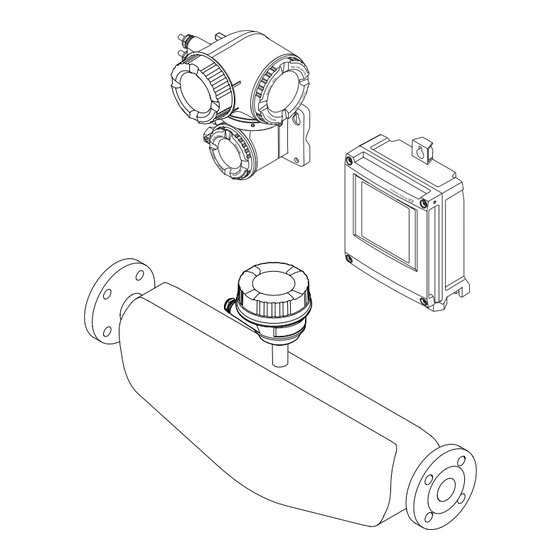
- Page 13 Proline Promass P 500 PROFIBUS DP Product description Product description The measuring system consists of a transmitter and a sensor. The transmitter and sensor are mounted in physically separate locations. They are interconnected by connecting cables. Product design Two versions of the transmitter are available.
- Page 14 Product description Proline Promass P 500 PROFIBUS DP 3.1.2 Proline 500 Signal transmission: analog Order code for "Integrated ISEM electronics", option B "Transmitter" For use in applications required to meet special requirements due to ambient or operating conditions. As the electronics are located in the transmitter, the device is ideal in the event of: •...
- Page 15 • Enter the serial numbers from the nameplates in the Device Viewer (www.endress.com/deviceviewer): all the information about the device is displayed. • Enter the serial numbers from the nameplates into the Endress+Hauser Operations app or scan the DataMatrix code on the nameplate with the Endress+Hauser Operations app: all the information about the device is displayed.
- Page 16 Incoming acceptance and product identification Proline Promass P 500 PROFIBUS DP 4.2.1 Transmitter nameplate Proline 500 – digital Order code: Ser. no.: Ext. ord. cd.: Date: A0029194 3 Example of a transmitter nameplate Name of the transmitter Manufacturer address/certificate holder...
- Page 17 Proline Promass P 500 PROFIBUS DP Incoming acceptance and product identification Proline 500 3 4 5 Order code: Ser. no.: Ext. ord. cd.: Date: A0029192 4 Example of a transmitter nameplate Manufacturer address/certificate holder Name of the transmitter Order code Serial number (Ser.
- Page 18 Incoming acceptance and product identification Proline Promass P 500 PROFIBUS DP 4.2.2 Sensor nameplate Order code: Ser. no.: Ext. ord. cd.: Date: A0029199 5 Example of a sensor nameplate Name of the sensor Manufacturer address/certificate holder Order code Serial number (Ser. no.) Extended order code (Ext.
- Page 19 Proline Promass P 500 PROFIBUS DP Incoming acceptance and product identification 4.2.3 Symbols on the device Symbol Meaning WARNING! This symbol alerts you to a dangerous situation. Failure to avoid this situation can result in serious or fatal injury. Please consult the documentation for the measuring instrument to discover the type of potential danger and measures to avoid it.
- Page 20 Storage and transport Proline Promass P 500 PROFIBUS DP Storage and transport Storage conditions Observe the following notes for storage: ‣ Store in the original packaging to ensure protection from shock. ‣ Do not remove protective covers or protective caps installed on process connections.
- Page 21 Proline Promass P 500 PROFIBUS DP Installation 5.2.2 Measuring devices with lifting lugs CAUTION Special transportation instructions for devices with lifting lugs ‣ Only use the lifting lugs fitted on the device or flanges to transport the device. ‣ The device must always be secured at two lifting lugs at least.
- Page 22 Installation Proline Promass P 500 PROFIBUS DP Installation in down pipes However, the following installation suggestion allows for installation in an open vertical pipeline. Pipe restrictions or the use of an orifice with a smaller cross-section than the nominal diameter prevent the sensor running empty while measurement is in progress.
- Page 23 Proline Promass P 500 PROFIBUS DP Installation Orientation Recommendation Horizontal orientation, transmitter at bottom Exception: → 7, 23 A0015590 Horizontal orientation, transmitter at side A0015592 This orientation is recommended to ensure self-draining. Applications with low process temperatures may reduce the ambient temperature. To maintain the minimum ambient temperature for the transmitter, this orientation is recommended.
- Page 24 Installation Proline Promass P 500 PROFIBUS DP 6.1.2 Environmental and process requirements Ambient temperature range Measuring device • –40 to +60 °C (–40 to +140 °F) • Order code for "Test, certificate", option JP: –50 to +60 °C (–58 to +140 °F) Readability of the local –20 to +60 °C (–4 to +140 °F)
- Page 25 Proline Promass P 500 PROFIBUS DP Installation NOTICE Electronics overheating on account of thermal insulation! ‣ Recommended orientation: horizontal orientation, sensor connection housing pointing downwards. ‣ Do not insulate the sensor connection housing. ‣ Maximum permissible temperature at the lower end of the sensor connection housing: 80 °C (176 °F)
- Page 26 Installation Proline Promass P 500 PROFIBUS DP 6.1.3 Special installation instructions Drainability When installed vertically, the measuring tube can be drained completely and protected against buildup. When the sensor is installed in a horizontal line, eccentric clamps can be used to ensure complete drainability.
- Page 27 Proline Promass P 500 PROFIBUS DP Installation [mm] [in] [mm] [in] [mm] [in] [mm] [in] ³⁄₈ 11.73 ½ 15.83 21.34 1 ½ 25.91 36.5 1.44 30.39 44.1 1.74 2.95 Zero verification and zero adjustment All measuring instruments are calibrated in accordance with state-of-the-art technology.
- Page 28 Installation Proline Promass P 500 PROFIBUS DP Weather protection cover 213 (8.4) 203 (8.0) A0029552 9 Weather protection cover for Proline 500 – digital; engineering unit mm (in) 280 (11.0) 255 (10.0) 146 (5.75) 134 (5.3) 12 (0.47) 30 (1.18) A0029553 ...
- Page 29 Proline Promass P 500 PROFIBUS DP Installation 3. Remove stick-on label on the electronics compartment cover. 6.2.3 Mounting the measuring device WARNING Danger due to improper process sealing! ‣ Ensure that the inside diameters of the gaskets are greater than or equal to that of the process connections and piping.
- Page 30 Installation Proline Promass P 500 PROFIBUS DP ø TX 25 20…70 ø ( 0.79…2.75) SW 10 A0029051 11 Unit mm (in) Wall mounting Required tools: Drill with drill bit ⌀ 6.0 mm 17 (0.67) 5.8 (0.23) 5.8 (0.23) 149 (5.85) A0029054 ...
- Page 31 Proline Promass P 500 PROFIBUS DP Installation 5. Tighten the fixing screws. 6.2.5 Mounting the transmitter housing: Proline 500 CAUTION Ambient temperature too high! Danger of electronics overheating and housing deformation. ‣ Do not exceed the permitted maximum ambient temperature.
- Page 32 Installation Proline Promass P 500 PROFIBUS DP 20 70 … ( 0.79 to 2.75) SW 13 A0029057 14 Engineering unit mm (in) 6.2.6 Turning the transmitter housing: Proline 500 To provide easier access to the connection compartment or display module, the transmitter housing can be turned.
- Page 33 Proline Promass P 500 PROFIBUS DP Installation – – – 3 mm A0030035 1. Depending on the device version: Loosen the securing clamp of the connection compartment cover. 2. Unscrew the connection compartment cover. 3. Turn the display module to the desired position: max. 8 × 45° in each direction.
- Page 34 Electrical connection Proline Promass P 500 PROFIBUS DP Electrical connection WARNING Live parts! Incorrect work performed on the electrical connections can result in an electric shock. ‣ Set up a disconnecting device (switch or power-circuit breaker) to easily disconnect the device from the supply voltage.
- Page 35 Proline Promass P 500 PROFIBUS DP Electrical connection Ethernet-APL Shielded twisted-pair cable. Cable type A is recommended. https://www.profibus.com Ethernet-APL White Paper " Current output 0 /4 to 20 mA (excluding HART) Standard installation cable is sufficient. Pulse /frequency /switch output Standard installation cable is sufficient.
- Page 36 Electrical connection Proline Promass P 500 PROFIBUS DP A0032476 Proline 500 digital transmitter Proline 500 transmitter Sensor Promass Non-hazardous area Hazardous area: Zone 2; Class I, Division 2 Hazardous area: Zone 1; Class I, Division 1 Standard cable to 500 digital transmitter → 36 Transmitter installed in the non-hazardous area or hazardous area: Zone 2;...
- Page 37 Proline Promass P 500 PROFIBUS DP Electrical connection Cross-section Cable length [max.] 1.00 mm (AWG 17) 240 m (720 ft) 1.50 mm (AWG 15) 300 m (900 ft) Optionally available connecting cable Design 2 × 2 × 0.34 mm (AWG 22) PVC cable with common shield (2 pairs, uninsulated stranded CU wires;...
- Page 38 Electrical connection Proline Promass P 500 PROFIBUS DP Cross-section Cable length [max.] Termination 2 x 2 x 0.50 mm 50 m (150 ft) 2 x 2 x 0.50 mm (AWG 20) (AWG 20) BN WT YE GN • +, – = 0.5 mm •...
- Page 39 Proline Promass P 500 PROFIBUS DP Electrical connection C: Connecting cable between sensor and transmitter: Proline 500 Design 6 × 0.38 mm PVC cable with individual shielded cores and common copper shield With order code for "Test, certificate", option JQ 7 ×...
- Page 40 Electrical connection Proline Promass P 500 PROFIBUS DP Experience shows that the best results with regard to EMC are achieved in most cases in installations with one-sided shielding on the feed side (without capacitance termination at the field device). Appropriate measures with regard to input wiring must be taken to allow unrestricted operation when EMC interference is present.
- Page 41 Proline Promass P 500 PROFIBUS DP Electrical connection NOTICE Insufficient sealing of the housing! Operational reliability of the measuring device could be compromised. ‣ Use suitable cable glands corresponding to the degree of protection. 1. Remove dummy plug if present.
- Page 42 Electrical connection Proline Promass P 500 PROFIBUS DP Connecting the measuring instrument: Proline 500 - digital NOTICE An incorrect connection compromises electrical safety! ‣ Only properly trained specialist staff may perform electrical connection work. ‣ Observe applicable federal/national installation codes and regulations.
- Page 43 Proline Promass P 500 PROFIBUS DP Electrical connection Connecting the sensor connection housing via terminals For the device version with the order code for "Sensor connection housing": Option A "Aluminum coated" 10 (0.4) 3 mm TX 20 TX 20 22 mm...
- Page 44 Electrical connection Proline Promass P 500 PROFIBUS DP Connecting the sensor connection housing via terminals For the device version with the order code for "Sensor connection housing": Option B "Stainless" 10 (0.4) 8 mm 22 mm 24 mm A0029613 1. Release the securing screw of the housing cover.
- Page 45 Proline Promass P 500 PROFIBUS DP Electrical connection Connecting the sensor connection housing via the connector For the device version with the order code for "Sensor connection housing": Option C "Ultra-compact hygienic, stainless" A0029615 1. Connect the protective ground. 2. Connect the connector.
- Page 46 Electrical connection Proline Promass P 500 PROFIBUS DP Connecting the connecting cable to the transmitter TX 20 TX 20 10 (0.4) 22 mm 24 mm A0029597 1. Loosen the 4 fixing screws on the housing cover. 2. Open the housing cover.
- Page 47 Proline Promass P 500 PROFIBUS DP Electrical connection 7.3.2 Connecting the signal cable and the supply voltage cable A0028200 Terminal connection for supply voltage Terminal connection for signal transmission, input/output Terminal connection for signal transmission, input/output Terminal connection for connecting cable between sensor and transmitter Terminal connection for signal transmission, input/output;...
- Page 48 Electrical connection Proline Promass P 500 PROFIBUS DP WARNING Housing degree of protection may be voided due to insufficient sealing of the housing. ‣ Screw in the screw without using any lubricant. NOTICE Excessive tightening torque applied to the fixing screws! Risk of damaging the plastic transmitter.
- Page 49 Proline Promass P 500 PROFIBUS DP Electrical connection Connecting the measuring instrument: Proline 500 NOTICE An incorrect connection compromises electrical safety! ‣ Only properly trained specialist staff may perform electrical connection work. ‣ Observe applicable federal/national installation codes and regulations.
- Page 50 Electrical connection Proline Promass P 500 PROFIBUS DP Connecting the sensor connection housing via terminals For the device version with the order code for "Housing": Option A "Aluminum coated" 10 (0.4) 3 mm 22 mm 24 mm A0029612 1. Loosen the securing clamp of the housing cover.
- Page 51 Proline Promass P 500 PROFIBUS DP Electrical connection Connecting the sensor connection housing via terminals For the device version with the order code for "Housing": Option B "Stainless" 10 (0.4) 8 mm 22 mm 24 mm A0029613 1. Release the securing screw of the housing cover.
- Page 52 Electrical connection Proline Promass P 500 PROFIBUS DP Attaching the connecting cable to the transmitter 10 (0.4) 3 mm 22 mm 24 mm A0029592 1. Loosen the securing clamp of the connection compartment cover. 2. Unscrew the connection compartment cover.
- Page 53 Proline Promass P 500 PROFIBUS DP Electrical connection Special connection instructions 7.6.1 Connection examples PROFIBUS DP A0028765 17 Connection example for PROFIBUS DP, non-hazardous area and Zone 2/Div. 2 Control system (e.g. PLC) Cable shield provided at one end. The cable shield must be grounded at both ends to comply with EMC requirements;...
- Page 54 Electrical connection Proline Promass P 500 PROFIBUS DP 4...20 mA A0028759 19 Connection example for 4-20 mA current output (passive) Automation system with current input (e.g. PLC) Active barrier for power supply (e.g. RN221N) Analog display unit: observe maximum load...
- Page 55 Proline Promass P 500 PROFIBUS DP Electrical connection Relay output A0028760 22 Connection example for relay output (passive) Automation system with relay input (e.g. PLC) Power supply Transmitter: observe input values → 251 Current input A0028915 23...
- Page 56 Electrical connection Proline Promass P 500 PROFIBUS DP Hardware settings 7.7.1 Setting the device address The address must always be configured for a PROFIBUS DP/PA device. The valid address range is between 1 and 126. In a PROFIBUS DP/PA network, each address can only be assigned once.
- Page 57 Proline Promass P 500 PROFIBUS DP Electrical connection Proline 500 transmitter Hardware addressing not used A0029637 Set the desired device address using the DIP switches in the connection compartment. A0029633 To switch addressing from software addressing to hardware addressing: set the DIP switch to On.
- Page 58 Electrical connection Proline Promass P 500 PROFIBUS DP Proline 500 – digital transmitter A0029675 1. Open the housing cover. 2. Remove the display module. 3. Fold open the terminal cover. 4. Set DIP switch no. 3 to ON. Proline 500 transmitter ‣...
- Page 59 Proline Promass P 500 PROFIBUS DP Electrical connection A0034500 1. Loosen the 4 fixing screws on the housing cover. 2. Open the housing cover. 3. Fold open the terminal cover. 4. Set DIP switch no. 2 on the I/O electronics module from OFF → ON.
- Page 60 Electrical connection Proline Promass P 500 PROFIBUS DP Ensuring the degree of protection The measuring instrument fulfills all the requirements for the degree of protection IP66/67, Type 4X enclosure. To guarantee the degree of protection IP66/67, Type 4X enclosure, carry out the following steps after the electrical connection: 1.
- Page 61 Proline Promass P 500 PROFIBUS DP Operation options Operation options Overview of operation options A0034513 Local operation via display module Computer with web browser or operating tool (e.g. FieldCare, DeviceCare, AMS Device Manager, SIMATIC PDM) Field Xpert SFX350 or SFX370...
- Page 62 Operation options Proline Promass P 500 PROFIBUS DP Structure and function of the operating menu 8.2.1 Structure of the operating menu For an overview of the operating menu for experts: see the "Description of Device Parameters" document supplied with the device → 274...
- Page 63 Proline Promass P 500 PROFIBUS DP Operation options 8.2.2 Operating philosophy The individual parts of the operating menu are assigned to certain user roles (e.g. operator, maintenance etc.). Each user role contains typical tasks within the device life cycle. Menu/parameter...
- Page 64 Operation options Proline Promass P 500 PROFIBUS DP Menu/parameter User role and tasks Content/meaning Expert Function- Tasks that require detailed knowledge of Contains all of the device parameters and allows direct access to these by oriented the function of the device: means of an access code.
- Page 65 Proline Promass P 500 PROFIBUS DP Operation options Display area In the display area, each measured value is prefaced by certain symbol types for further description: Measured variable Measurement channel Diagnostic behavior number ↓ ↓ ↓ Example Appears only if a diagnostics event is present for this measured variable.
- Page 66 Operation options Proline Promass P 500 PROFIBUS DP Diagnostic behavior Symbol Meaning Alarm • Measurement is interrupted. • Signal outputs and totalizers assume the defined alarm condition. • A diagnostic message is generated. Warning • Measurement is resumed. • The signal outputs and totalizers are not affected.
- Page 67 Proline Promass P 500 PROFIBUS DP Operation options 8.3.2 Navigation view In the submenu In the wizard /../Operation 0091-1 /../Select medium Access stat.disp Select medium Operator Liquid Locking status Display A0013993-EN A0013995-EN Navigation view Navigation path to current position Status area Display area for navigation Operating elements →...
- Page 68 Operation options Proline Promass P 500 PROFIBUS DP Setup Is displayed: • In the menu next to the "Setup" selection • At the left in the navigation path in the Setup menu Diagnosis Is displayed: • In the menu next to the "Diagnostics" selection •...
- Page 69 Proline Promass P 500 PROFIBUS DP Operation options 8.3.3 Editing view Numeric editor +0.000 Xx – A0034250 26 For entering values in parameters (e.g. limit values) Entry display area Input screen Confirm, delete or reject entry Operating elements Text editor...
- Page 70 Operation options Proline Promass P 500 PROFIBUS DP Operating key Meaning Enter key • Pressing the key briefly confirms your selection. • Pressing the key for 2 s confirms your entry. Escape key combination (press keys simultaneously) Close the editing view without accepting a change.
- Page 71 Proline Promass P 500 PROFIBUS DP Operation options 8.3.4 Operating elements Operating key Meaning Minus key In menu, submenu Moves the selection bar upwards in a picklist In wizards Goes to previous parameter In the text and numeric editor Move the entry position to the left.
- Page 72 Operation options Proline Promass P 500 PROFIBUS DP Calling up and closing the context menu The user is in the operational display. 1. Press the and keys for longer than 3 seconds. The context menu opens. XXXXXXXXXX Setup Conf.backup...
- Page 73 Proline Promass P 500 PROFIBUS DP Operation options 8.3.6 Navigating and selecting from list Different operating elements are used to navigate through the operating menu. The navigation path is displayed on the left in the header. Icons are displayed in front of the individual menus.
- Page 74 Operation options Proline Promass P 500 PROFIBUS DP The direct access code consists of a 5-digit number (at maximum) and the channel number, which identifies the channel of a process variable: e.g. 00914-2. In the navigation view, this appears on the right-hand side in the header of the selected parameter.
- Page 75 Proline Promass P 500 PROFIBUS DP Operation options Ent. access code Invalid or out of range input value Min:0 Max:9999 A0014049-EN For a description of the editing view - consisting of the text editor and numeric editor - with symbols → 69, for a description of the operating elements → 71 8.3.10...
- Page 76 Operation options Proline Promass P 500 PROFIBUS DP 2. Enter the access code. The -symbol in front of the parameters disappears; all previously write- protected parameters are now re-enabled. 8.3.12 Enabling and disabling the keypad lock The keypad lock makes it possible to block access to the entire operating menu via local operation.
- Page 77 Proline Promass P 500 PROFIBUS DP Operation options 8.4.2 Requirements Computer hardware Hardware Interface CDI-RJ45 WLAN Interface The computer must have a RJ45 The operating unit must have a WLAN interface. interface. Connection Standard Ethernet cable Connection via Wireless LAN.
- Page 78 Operation options Proline Promass P 500 PROFIBUS DP Measuring device: Via CDI-RJ45 service interface Device CDI-RJ45 service interface Measuring device The measuring device has an RJ45 interface. Web server Web server must be enabled; factory setting: ON For information on enabling the Web server → 82...
- Page 79 Proline Promass P 500 PROFIBUS DP Operation options IP address 192.168.1.XXX; for XXX all numerical sequences except: 0, 212 and 255 → e.g. 192.168.1.213 Subnet mask 255.255.255.0 Default gateway 192.168.1.212 or leave cells empty Via WLAN interface Configuring the Internet protocol of the mobile terminal NOTICE If the WLAN connection is lost during the configuration, settings made may be lost.
- Page 80 Operation options Proline Promass P 500 PROFIBUS DP 2. Enter the IP address of the web server in the address line of the web browser: 192.168.1.212 The login page appears. 2 3 4 Device name: Device tag: Signal Status:...
- Page 81 Proline Promass P 500 PROFIBUS DP Operation options 8.4.5 User interface A0029418 Function row Local display language Navigation area Header The following information appears in the header: • Device name • Device tag • Device status with status signal → 177 •...
- Page 82 Operation options Proline Promass P 500 PROFIBUS DP Navigation area The menus, the associated submenus and parameters can be selected in the navigation area. Working area Depending on the selected function and the related submenus, various actions can be performed in this area: •...
- Page 83 Proline Promass P 500 PROFIBUS DP Operation options 3. If no longer needed: Reset the modified properties of the Internet protocol (TCP/IP) → 78. Access to the operating menu via the operating tool The structure of the operating menu in the operating tools is the same as for operation via the local display.
- Page 84 Operation options Proline Promass P 500 PROFIBUS DP Proline 500 – digital transmitter open press A0029163 30 Connection via service interface (CDI-RJ45) Computer with web browser (e.g. Microsoft Internet Explorer, Microsoft Edge) for accessing the integrated web server or with "FieldCare" operating tool, "DeviceCare" with COM DTM "CDI Communication TCP/IP"...
- Page 85 Proline Promass P 500 PROFIBUS DP Operation options A0034569 Transmitter with integrated WLAN antenna Transmitter with external WLAN antenna LED lit constantly: WLAN reception is enabled on measuring device LED flashing: WLAN connection established between operating unit and measuring device Computer with WLAN interface and web browser (e.g.
- Page 86 FieldCare Function range FDT-based (Field Device Technology) plant asset management tool from Endress+Hauser. It can configure all smart field units in a system and helps you manage them. By using the status information, it is also a simple but effective way of checking their status and condition.
- Page 87 Display area for current measured values Editing toolbar with additional functions such as save/load, event list and create documentation Navigation area with operating menu structure Work area Action area Status area 8.5.3 DeviceCare Function range Tool for connecting and configuring Endress+Hauser field devices. Endress+Hauser...
- Page 88 Operation options Proline Promass P 500 PROFIBUS DP The fastest way to configure Endress+Hauser field devices is with the dedicated "DeviceCare" tool. Together with the device type managers (DTMs) it presents a convenient, comprehensive solution. Innovation brochure IN01047S Source for device description files → 89...
- Page 89 Proline Promass P 500 PROFIBUS DP System integration System integration Overview of device description files 9.1.1 Current version data for the device Firmware version 01.00.zz • On the title page of the manual • On the transmitter nameplate • Firmware version Diagnostics →...
- Page 90 System integration Proline Promass P 500 PROFIBUS DP 9.2.1 Manufacturer-specific GSD This GSD guarantees the unrestricted functionality of the measuring device. Device-specific process parameters and functions are therefore available. Manufacturer-specific GSD ID number File name PROFIBUS DP 0x156F EH3x156F.gsd Use manufacturer-specific GSD Assignment is performed in the Ident number selector parameter via the Manufacturer option.
- Page 91 Proline Promass P 500 PROFIBUS DP System integration 9.3.1 Automatic identification (factory setting) The Promass 500 PROFIBUS DP automatically recognizes the measuring device configured in the automation system (Promass 83 PROFIBUS DP) and makes the same input and output data and measured value status information available for cyclic data exchange.
- Page 92 System integration Proline Promass P 500 PROFIBUS DP Using the GSD modules of the previous model In the compatibility mode, all the modules already configured in the automation system are generally supported during cyclic data transmission. However, Promass 500 does not perform further processing for the following modules, i.e.
- Page 93 Proline Promass P 500 PROFIBUS DP System integration Cyclic data transmission Cyclic data transmission when using the device master file (GSD). 9.5.1 Block model The block model shows which input and output data the measuring device makes available for cyclic data exchange. Cyclic data exchange takes place with a PROFIBUS master (Class 1), e.g.
- Page 94 System integration Proline Promass P 500 PROFIBUS DP AI module (Analog Input) Transmit an input variable from the measuring device to the PROFIBUS master (Class 1). The selected input variable including its status is cyclically transmitted to the PROFIBUS master (Class 1) via the AI module. The input variable is depicted in the first four bytes in the form of a floating point number as per the IEEE 754 standard.
- Page 95 Proline Promass P 500 PROFIBUS DP System integration Factory setting Function block Factory setting AI 1 Mass flow AI 2 Volume flow AI 3 Corrected volume flow AI 4 Density AI 5 Mass flow AI 6 Temperature AI 7 Mass flow...
- Page 96 System integration Proline Promass P 500 PROFIBUS DP SETTOT_TOTAL module The module combination consists of the SET_TOT and TOTAL functions: • SETTOT: Control the totalizers via the PROFIBUS master. • TOTAL: Transmit totalizer value incl. status to PROFIBUS master. Three Totalizer blocks are available (slot 9 to 11).
- Page 97 Proline Promass P 500 PROFIBUS DP System integration Data structure Output data of SETTOT and MODETOT Byte 1 Byte 2 Control variable 1: SETTOT Control variable 2: MODETOT Input data of TOTAL Byte 1 Byte 2 Byte 3 Byte 4...
- Page 98 System integration Proline Promass P 500 PROFIBUS DP The DI module cyclically transmits the discrete input value, including the status, to the PROFIBUS master (class 1). The discrete input value is depicted in the first byte. The second byte contains standardized status information pertaining to the input value.
- Page 99 Proline Promass P 500 PROFIBUS DP System integration Function block Device function Values: control (meaning) DO 6 (I/O 4) Assignment of medium type DO 7 Concentration (see the following table) Only available with the Heartbeat Verification application package Only available with the Concentration application package...
- Page 100 System integration Proline Promass P 500 PROFIBUS DP modules. The GSD file contains a description of the individual modules along with their individual properties. The modules are permanently assigned to the slots. When configuring the modules, it is absolutely essential to observe the sequence/arrangement of the modules. Any gaps between the configured modules must be filled with the EMPTY_MODULE.
- Page 101 1001 : °C 1002 : °F 1000 : K 1003 : °R For more information on the "slot/index table", please contact the Endress+Hauser Sales Center. 9.6.4 Accessing data via PROFIBUS DP The PROFIBUS master uses the indexes 230 to 245 in slot 0 to access the address shifting data area.
- Page 102 System integration Proline Promass P 500 PROFIBUS DP parameter via address shifting, the master can read out the current volume flow measured value in slot 0 and index 230. The data type (integer/float) and data access (read/write) depend on the parameter entered in the configuration area.
- Page 103 Proline Promass P 500 PROFIBUS DP Commissioning Commissioning 10.1 Post-mounting and post-connection check Before commissioning the device: ‣ Make sure that the post-installation and post-connection checks have been performed successfully. • Checklist for "Post-installation" check→ 33 • Checklist for "Post-connection" check→ 60 10.2...
- Page 104 Commissioning Proline Promass P 500 PROFIBUS DP X X X X X X X 20.50 Main menu 0104-1 Display language English Operation Setup Display language 0104-1 English à Deutsch Español Français Display language 0104-1 à English Deutsch Español Français Hauptmenü...
- Page 105 Proline Promass P 500 PROFIBUS DP Commissioning Navigation "Setup" menu Setup Device tag → 106 ‣ System units → 106 ‣ → 109 Medium selection ‣ Communication → 109 ‣ Analog inputs → 111 ‣...
- Page 106 Commissioning Proline Promass P 500 PROFIBUS DP XXXXXXXXX A0029422 34 Header of the operational display with tag name Tag name Enter the tag name in the "FieldCare" operating tool → 87 Navigation "Setup" menu → Device tag Parameter overview with brief description...
- Page 107 Proline Promass P 500 PROFIBUS DP Commissioning Temperature unit → 108 Pressure unit → 108 Parameter overview with brief description Parameter Description Selection Factory setting Mass flow unit Select mass flow unit. Unit choose list Country-specific: • kg/h Effect •...
- Page 108 Commissioning Proline Promass P 500 PROFIBUS DP Parameter Description Selection Factory setting Temperature unit Select temperature unit. Unit choose list Country-specific: • °C Effect • °F The selected unit applies to: • Electronic temperature parameter (6053) • Maximum value parameter (6051) •...
- Page 109 Proline Promass P 500 PROFIBUS DP Commissioning 10.6.3 Selecting and setting the medium The Select medium wizard submenu contains parameters that must be configured in order to select and set the medium. Navigation "Setup" menu → Medium selection ‣ Medium selection Select medium →...
- Page 110 Commissioning Proline Promass P 500 PROFIBUS DP Navigation "Setup" menu → Communication ‣ Communication Device address → 110 Parameter overview with brief description Parameter Description User entry Device address Enter device address. 0 to 126 Endress+Hauser...
- Page 111 Proline Promass P 500 PROFIBUS DP Commissioning 10.6.5 Configuration of the Analog Inputs The Analog inputs submenu guides the user systematically to the individual Analog input 1 to n submenu. From here you get to the parameters of the individual analog input.
- Page 112 Commissioning Proline Promass P 500 PROFIBUS DP Parameter Prerequisite Description Selection / User entry Fail-safe type – Select the failure mode. • Fail-safe value • Fallback value • Off Fail-safe value In Fail-safe type parameter, the Fail- Specify the values to be output when an Signed floating-point safe value option is selected.
- Page 113 Proline Promass P 500 PROFIBUS DP Commissioning 10.6.7 Configuring the current input The "Current input" wizard guides the user systematically through all the parameters that have to be set for configuring the current input. Navigation "Setup" menu → Current input ‣...
- Page 114 Commissioning Proline Promass P 500 PROFIBUS DP 10.6.8 Configuring the status input The Status input submenu guides the user systematically through all the parameters that have to be set for configuring the status input. Navigation "Setup" menu → Status input 1 to n ‣...
- Page 115 Proline Promass P 500 PROFIBUS DP Commissioning Navigation "Setup" menu → Current output ‣ Current output 1 to n Terminal number → 115 Signal mode → 115 → 116 Assign current output 1 to n Current span →...
- Page 116 Commissioning Proline Promass P 500 PROFIBUS DP Parameter Prerequisite Description User interface / Factory setting Selection / User entry Assign current output 1 to n – Select process variable for • Off – current output. • Mass flow • Volume flow • Corrected volume flow •...
- Page 117 Proline Promass P 500 PROFIBUS DP Commissioning Parameter Prerequisite Description User interface / Factory setting Selection / User entry Damping output 1 to n A process variable is selected Set reaction time for output 0.0 to 999.9 s – in the Assign current output signal to fluctuations in the parameter (→...
- Page 118 Commissioning Proline Promass P 500 PROFIBUS DP 10.6.10 Configuring the pulse/frequency/switch output The Pulse/frequency/switch output wizard guides you systematically through all the parameters that can be set for configuring the selected output type. Navigation "Setup" menu → Advanced setup → Pulse/frequency/switch output ‣...
- Page 119 Proline Promass P 500 PROFIBUS DP Commissioning Parameter overview with brief description Parameter Prerequisite Description Selection / User Factory setting interface / User entry Operating mode – Define the output as a pulse, • Pulse – frequency or switch output. • Frequency • Switch Terminal number –...
- Page 120 Commissioning Proline Promass P 500 PROFIBUS DP Configuring the frequency output Navigation "Setup" menu → Pulse/frequency/switch output ‣ Pulse/frequency/switch output 1 to n Operating mode → 120 Terminal number → 120 Signal mode → 120 Assign frequency output →...
- Page 121 Proline Promass P 500 PROFIBUS DP Commissioning Parameter Prerequisite Description Selection / User Factory setting interface / User entry Assign frequency output The Frequency option is Select process variable for • Off – selected in Operating mode frequency output. • Mass flow parameter (→ 118).
- Page 122 Commissioning Proline Promass P 500 PROFIBUS DP Parameter Prerequisite Description Selection / User Factory setting interface / User entry Measuring value at maximum The Frequency option is Enter measured value for Signed floating-point Depends on country frequency selected in the Operating maximum frequency. number and nominal mode parameter (→...
- Page 123 Proline Promass P 500 PROFIBUS DP Commissioning Configuring the switch output Navigation "Setup" menu → Pulse/frequency/switch output ‣ Pulse/frequency/switch output 1 to n Operating mode → 123 Terminal number → 123 Signal mode → 123 Switch output function →...
- Page 124 Commissioning Proline Promass P 500 PROFIBUS DP Parameter Prerequisite Description Selection / User Factory setting interface / User entry Switch output function The Switch option is selected Select function for switch • Off – in the Operating mode output. • On parameter. • Diagnostic behavior •...
- Page 125 Proline Promass P 500 PROFIBUS DP Commissioning Parameter Prerequisite Description Selection / User Factory setting interface / User entry Switch-off value • The Switch option is Enter measured value for the Signed floating-point Depends on country: selected in the Operating switch-off point. number • 0 kg/h mode parameter.
- Page 126 Commissioning Proline Promass P 500 PROFIBUS DP Switch-on value → 127 Switch-on delay → 127 → 127 Failure mode Switch status → 127 Powerless relay status → 127 Parameter overview with brief description Parameter Prerequisite Description User interface / ...
- Page 127 Proline Promass P 500 PROFIBUS DP Commissioning Parameter Prerequisite Description User interface / Factory setting Selection / User entry Assign status In the Relay output function Select device status for switch • Partially filled pipe – parameter, the Digital Output output. detection option is selected.
- Page 128 Commissioning Proline Promass P 500 PROFIBUS DP 100% bargraph value 3 → 129 Value 4 display → 129 Parameter overview with brief description Parameter Prerequisite Description Selection / User Factory setting entry Format display A local display is provided. Select how measured values •...
- Page 129 Proline Promass P 500 PROFIBUS DP Commissioning Parameter Prerequisite Description Selection / User Factory setting entry 100% bargraph value 1 A local display is provided. Enter 100% value for bar Signed floating-point Depends on country graph display. number and nominal diameter Value 2 display A local display is provided.
- Page 130 Commissioning Proline Promass P 500 PROFIBUS DP 10.6.13 Configuring the low flow cut off The Low flow cut off wizard systematically guides the user through all the parameters that must be set to configure low flow cut off. Navigation "Setup" menu → Low flow cut off ‣...
- Page 131 Proline Promass P 500 PROFIBUS DP Commissioning 10.6.14 Configuring partially filled pipe detection The Partial filled pipe detection wizard guides you systematically through all parameters that have to be set for configuring the monitoring of the pipe filling. Navigation "Setup" menu → Partially filled pipe detection ‣...
- Page 132 Commissioning Proline Promass P 500 PROFIBUS DP 10.7 Advanced settings The Advanced setup submenu with its submenus contains parameters for specific settings. Navigation to the "Advanced setup" submenu X X X X X X X 20.50 0104-1 Main menu Display language English Display/operat.
- Page 133 Proline Promass P 500 PROFIBUS DP Commissioning ‣ Totalizer 1 to n → 140 ‣ → 142 Display ‣ WLAN settings ‣ Concentration ‣ Heartbeat setup ‣ Configuration backup → 146 ‣ Administration → 147 10.7.1...
- Page 134 Commissioning Proline Promass P 500 PROFIBUS DP Parameter overview with brief description Parameter Prerequisite Description Selection / User Factory setting interface / User entry Corrected volume flow calculation – Select reference density for • Fixed reference – calculating the corrected density volume flow. • Calculated reference density •...
- Page 135 Proline Promass P 500 PROFIBUS DP Commissioning ‣ Zero verification → 138 ‣ Zero adjustment → 139 Parameter overview with brief description Parameter Description Selection Installation direction Set sign of flow direction to match the direction of the arrow on •...
- Page 136 Commissioning Proline Promass P 500 PROFIBUS DP If the adjustment was completed successfully, the Density adjustment factor parameter and the Density adjustment offset parameter and the values calculated for them are shown on the display. "2 point adjustment" option 1. In the Density adjustment mode parameter, select the 2 point adjustment option and confirm.
- Page 137 Proline Promass P 500 PROFIBUS DP Commissioning Density adjustment factor → 137 Density adjustment offset → 137 Parameter overview with brief description Parameter Prerequisite Description Selection / User Factory setting entry / User interface Density adjustment mode – • 1 point adjustment –...
- Page 138 Commissioning Proline Promass P 500 PROFIBUS DP Zero verification and zero adjustment cannot be performed if the following process conditions are present: • Gas pockets Ensure that the system has been sufficiently flushed with the medium. Repeat flushing can help to eliminate gas pockets •...
- Page 139 Proline Promass P 500 PROFIBUS DP Commissioning Parameter Description Selection / User interface Factory setting Zero point adjustment status • Busy – • Alarm • Ok Additional information Indicate whether to display additional • Hide – information. • Show Recommendation: Indicates whether an adjustment is •...
- Page 140 Commissioning Proline Promass P 500 PROFIBUS DP Zero point measured → 140 Zero point standard deviation → 140 → 140 Select action Parameter overview with brief description Parameter Description Selection / User interface Factory setting Process conditions Ensure process conditions as follows.
- Page 141 Proline Promass P 500 PROFIBUS DP Commissioning Unit totalizer → 141 Totalizer operation mode → 141 → 141 Control Totalizer 1 to n Failure mode → 141 Parameter overview with brief description Parameter Description Selection Factory setting Assign process variable Select process variable for totalizer.
- Page 142 Commissioning Proline Promass P 500 PROFIBUS DP 10.7.4 Carrying out additional display configurations In the Display submenu you can set all the parameters associated with the configuration of the local display. Navigation "Setup" menu → Advanced setup → Display ‣...
- Page 143 Proline Promass P 500 PROFIBUS DP Commissioning Parameter overview with brief description Parameter Prerequisite Description Selection / User Factory setting entry Format display A local display is provided. Select how measured values • 1 value, max. size – are shown on the display.
- Page 144 Commissioning Proline Promass P 500 PROFIBUS DP Parameter Prerequisite Description Selection / User Factory setting entry Decimal places 1 A measured value is specified Select the number of decimal • x – in the Value 1 display places for the display value.
- Page 145 Proline Promass P 500 PROFIBUS DP Commissioning Parameter Prerequisite Description Selection / User Factory setting entry Display damping A local display is provided. Set display reaction time to 0.0 to 999.9 s – fluctuations in the measured value. Header A local display is provided.
- Page 146 Commissioning Proline Promass P 500 PROFIBUS DP Parameter overview with brief description Parameter Prerequisite Description User entry / Factory setting Selection WLAN IP address – Enter IP address of the device 4 octet: 0 to 255 (in – WLAN interface. the particular octet) Network security –...
- Page 147 Proline Promass P 500 PROFIBUS DP Commissioning Parameter overview with brief description Parameter Description User interface / Selection Operating time Indicates how long the device has been in operation. Days (d), hours (h), minutes (m) and seconds Last backup Shows when the last data backup was saved to HistoROM Days (d), hours (h), minutes (m) and seconds backup.
- Page 148 Commissioning Proline Promass P 500 PROFIBUS DP Navigation "Setup" menu → Advanced setup → Administration ‣ Administration ‣ Define access code → 148 ‣ Reset access code → 148 → 149 Device reset Using the parameter to define the access code Navigation "Setup"...
- Page 149 Reset access code to factory settings. Character string comprising numbers, letters and special characters For a reset code, contact your Endress+Hauser service organization. The reset code can only be entered via: • Web browser • DeviceCare, FieldCare (via CDI-RJ45 service interface) •...
- Page 150 Commissioning Proline Promass P 500 PROFIBUS DP Value current output 1 to n → 150 Frequency output simulation 1 to n → 150 → 151 Frequency value 1 to n Pulse output simulation 1 to n → 151 Pulse value 1 to n →...
- Page 151 Proline Promass P 500 PROFIBUS DP Commissioning Parameter Prerequisite Description Selection / User entry Frequency value 1 to n In the Frequency output simulation Enter the frequency value for the 0.0 to 12 500.0 Hz 1 to n parameter, the On option is simulation.
- Page 152 Commissioning Proline Promass P 500 PROFIBUS DP 10.9.1 Write protection via access code The effects of the user-specific access code are as follows: • Via local operation, the parameters for the measuring device configuration are write- protected and their values can no longer be changed.
- Page 153 Via Web browser, FieldCare, DeviceCare (via CDI-RJ45 service interface), fieldbus You can only obtain a reset code from your local Endress+Hauser service organization. The code must be calculated explicitly for every device. 1. Note down the serial number of the device.
- Page 154 Commissioning Proline Promass P 500 PROFIBUS DP Proline 500 – digital Enable/disable write protection A0029673 1. Open the housing cover. 2. Remove the display module. 3. Fold open the terminal cover. 4. Enable or disable write protection: Setting the write protection (WP) switch on the main electronics module to the ON position enables hardware write protection/setting to OFF (factory setting) disables hardware write protection.
- Page 155 Proline Promass P 500 PROFIBUS DP Commissioning Proline 500 A0029630 Setting the write protection (WP) switch on the main electronics module to the ON position enables hardware write protection. In the Locking status parameter, the Hardware locked option is displayed →...
- Page 156 Operation Proline Promass P 500 PROFIBUS DP Operation 11.1 Reading off the device locking status Device active write protection: Locking status parameter Operation → Locking status Function scope of the "Locking status" parameter Options Description None The access authorization displayed in the Access status parameter applies →...
- Page 157 Proline Promass P 500 PROFIBUS DP Operation 11.4.1 "Measured variables" submenu The Measured variables submenu contains all the parameters needed to display the current measured values for each process variable. Navigation "Diagnostics" menu → Measured values → Measured variables ‣...
- Page 158 Operation Proline Promass P 500 PROFIBUS DP Parameter Prerequisite Description User interface Corrected volume flow – Displays the corrected volume flow that Signed floating-point is currently calculated. number Dependency The unit is taken from: Corrected volume flow unit parameter (→ 107) Density –...
- Page 159 Proline Promass P 500 PROFIBUS DP Operation Parameter Prerequisite Description User interface Carrier corrected volume flow With the following conditions: Displays the corrected volume flow Signed floating-point • Order code for "Application package", currently measured for the carrier fluid. number option ED "Concentration"...
- Page 160 Operation Proline Promass P 500 PROFIBUS DP Parameter overview with brief description Parameter Prerequisite Description Selection / User entry / User interface Assign process variable – Select process variable for totalizer. • Mass flow • Volume flow • Corrected volume flow • Target mass flow •...
- Page 161 Proline Promass P 500 PROFIBUS DP Operation Navigation "Diagnostics" menu → Measured values → Input values → Current input 1 to n ‣ Current input 1 to n Measured values 1 to n → 161 Measured current 1 to n →...
- Page 162 Operation Proline Promass P 500 PROFIBUS DP ‣ Pulse/frequency/switch output → 162 1 to n ‣ Relay output 1 to n → 163 Output values of current output The Value current output submenu contains all the parameters needed to display the current measured values for every current output.
- Page 163 Proline Promass P 500 PROFIBUS DP Operation Parameter overview with brief description Parameter Prerequisite Description User interface Output frequency 1 to n In the Operating mode parameter, the Displays the value currently measured 0.0 to 12 500.0 Hz Frequency option is selected.
- Page 164 Operation Proline Promass P 500 PROFIBUS DP Function range of "Control Totalizer " parameter Options Description Totalize The totalizer is started. Reset + hold The totaling process is stopped and the totalizer is reset to 0. Preset + hold The totaling process is stopped and the totalizer is set to its defined start value from the Preset value 1 to n parameter.
- Page 165 Proline Promass P 500 PROFIBUS DP Operation • x-axis: depending on the number of channels selected displays 250 to 1000 measured values of a process variable. • y-axis: displays the approximate measured value span and constantly adapts this to the ongoing measurement.
- Page 166 Operation Proline Promass P 500 PROFIBUS DP Parameter overview with brief description Parameter Prerequisite Description Selection / User entry / User interface Assign channel 1 The Extended HistoROM application Assign process variable to logging • Off package is available. channel. • Mass flow •...
- Page 167 Proline Promass P 500 PROFIBUS DP Operation Parameter Prerequisite Description Selection / User entry / User interface Data logging – Select the type of data logging. • Overwriting • Not overwriting Logging delay In the Data logging parameter, the Not Enter the time delay for measured 0 to 999 h overwriting option is selected.
- Page 168 Diagnostics and troubleshooting Proline Promass P 500 PROFIBUS DP Diagnostics and troubleshooting 12.1 General troubleshooting For local display Error Possible causes Remedial action Local display is dark, but signal output is within The cable of the display module is not plugged in...
- Page 169 Proline Promass P 500 PROFIBUS DP Diagnostics and troubleshooting For access Fault Possible causes Remedial action Write access to parameters is not possible. Hardware write protection is enabled. Set the write protection switch on the main electronics module to the OFF position →...
- Page 170 Diagnostics and troubleshooting Proline Promass P 500 PROFIBUS DP Fault Possible causes Remedial action Operation with FieldCare or DeviceCare via Firewall of the PC or network is blocking Depending on the settings of the firewall used service interface CDI-RJ45 (port 8000) is not communication.
- Page 171 Proline Promass P 500 PROFIBUS DP Diagnostics and troubleshooting 12.2 Diagnostic information via light emitting diodes 12.2.1 Transmitter Proline 500 – digital Different LEDs in the transmitter provide information on the device status. A0029689 Supply voltage Device status Not used...
- Page 172 Diagnostics and troubleshooting Proline Promass P 500 PROFIBUS DP Color Meaning Communication Device does not receive any Profibus data. White Device receives Profibus data. Service interface (CDI), Not connected or no connection established. Ethernet Link/Activity Yellow Connected and connection established.
- Page 173 Proline Promass P 500 PROFIBUS DP Diagnostics and troubleshooting 12.2.2 Sensor connection housing Proline 500 – digital Various light emitting diodes (LED) on the ISEM electronics unit (intelligent sensor electronics module) in the sensor connection housing provide information about the device status.
- Page 174 Diagnostics and troubleshooting Proline Promass P 500 PROFIBUS DP 12.3 Diagnostic information on local display 12.3.1 Diagnostic message Faults detected by the self-monitoring system of the measuring device are displayed as a diagnostic message in alternation with the operational display.
- Page 175 Proline Promass P 500 PROFIBUS DP Diagnostics and troubleshooting Diagnostic behavior Symbol Meaning Alarm • Measurement is interrupted. • Signal outputs and totalizers assume the defined alarm condition. • A diagnostic message is generated. Warning • Measurement is resumed. • The signal outputs and totalizers are not affected.
- Page 176 Diagnostics and troubleshooting Proline Promass P 500 PROFIBUS DP 12.3.2 Calling up remedial measures X X X X X X X X X X X X X X 20.50 S801 Supply voltage Menu Diagnostic list Diagnostics 1 S801 Supply voltage...
- Page 177 Proline Promass P 500 PROFIBUS DP Diagnostics and troubleshooting A0031056 Status area with status signal Diagnostic information Remedial measures with service ID In addition, diagnostic events which have occurred can be shown in the Diagnostics menu: • Via parameter → 233 •...
- Page 178 Diagnostics and troubleshooting Proline Promass P 500 PROFIBUS DP Xxxxxx/…/…/ Device name: Xxxxxxx Mass flow: kg/h 12.34 Device tag: Xxxxxxx Volume flow: 12.34 m /h ³ Status signal: Function check (C) Xxxxxx Diagnostics 1: C485 Simu... Remedy information: Deactivate... Failure (F)
- Page 179 Proline Promass P 500 PROFIBUS DP Diagnostics and troubleshooting The user is in the Diagnostics menu. 1. Call up the desired parameter. 2. On the right in the working area, mouse over the parameter. A tool tip with remedy information for the diagnostic event appears.
- Page 180 Diagnostics and troubleshooting Proline Promass P 500 PROFIBUS DP Coding Measuring value (hex) Byte 5 Quality Quality Substatus Limits A0032228-EN 37 Structure of the coding byte The content of the coding byte depends on the configured failure mode in the individual function block.
- Page 181 Proline Promass P 500 PROFIBUS DP Diagnostics and troubleshooting Diagnostic information pertaining to the electronics: diagnostic number 200 to 399 Diagnostic number 200 to 301, 303 to 399 Measured value status (fixed assignment) Diagnostic behavior Device diagnostics Quality Coding Category...
- Page 182 Diagnostics and troubleshooting Proline Promass P 500 PROFIBUS DP 12.7 Overview of diagnostic information • The amount of diagnostic information and the number of measured variables affected increase if the measuring device has one or more application packages. • All of the measured variables affected in the entire Promass instrument family are always listed under "Measured variables affected".
- Page 183 Proline Promass P 500 PROFIBUS DP Diagnostics and troubleshooting Diagnostic information Remedy instructions Short text 046 Sensor limit exceeded 1. Inspect sensor 2. Check process condition Measured variable status [from the factory] Quality Good Quality substatus Maintenance demanded Coding (hex)
- Page 184 Diagnostics and troubleshooting Proline Promass P 500 PROFIBUS DP Diagnostic information Remedy instructions Short text 062 Sensor connection faulty 1. Check or replace sensor electronic module (ISEM) 2. If available: Check connection cable between sensor and transmitter Measured variable status 3.
- Page 185 Proline Promass P 500 PROFIBUS DP Diagnostics and troubleshooting Diagnostic information Remedy instructions Short text 082 Data storage 1. Check module connections 2. Contact service Measured variable status Quality Quality substatus Maintenance alarm Coding (hex) 0x24 to 0x27 Status signal...
- Page 186 Diagnostics and troubleshooting Proline Promass P 500 PROFIBUS DP Diagnostic information Remedy instructions Short text 083 Memory content 1. Restart device 2. Restore HistoROM S-DAT backup (' D evice reset' parameter) Measured variable status 3. Replace HistoROM S-DAT Quality Quality substatus...
- Page 187 Proline Promass P 500 PROFIBUS DP Diagnostics and troubleshooting Diagnostic information Remedy instructions Short text 140 Sensor signal asymmetrical 1. Check or replace sensor electronic module (ISEM) 2. If available: Check connection cable between sensor and transmitter Measured variable status [from the factory] 3.
- Page 188 Diagnostics and troubleshooting Proline Promass P 500 PROFIBUS DP Diagnostic information Remedy instructions Short text 144 Measuring error too high 1. Check or change sensor 2. Check process conditions Measured variable status [from the factory] Quality Quality substatus Maintenance alarm...
- Page 189 Proline Promass P 500 PROFIBUS DP Diagnostics and troubleshooting 12.7.2 Diagnostic of electronic Diagnostic information Remedy instructions Short text 201 Device failure 1. Restart device 2. Contact service Measured variable status Quality Quality substatus Maintenance alarm Coding (hex) 0x24 to 0x27...
- Page 190 Diagnostics and troubleshooting Proline Promass P 500 PROFIBUS DP Diagnostic information Remedy instructions Short text 242 Software incompatible 1. Check software 2. Flash or change main electronics module Measured variable status Quality Quality substatus Maintenance alarm Coding (hex) 0x24 to 0x27...
- Page 191 Proline Promass P 500 PROFIBUS DP Diagnostics and troubleshooting Diagnostic information Remedy instructions Short text 252 Modules incompatible 1. Check electronic modules 2. Check if correct modules are available (e.g. NEx, Ex) Measured variable status 3. Replace electronic modules Quality...
- Page 192 Diagnostics and troubleshooting Proline Promass P 500 PROFIBUS DP Diagnostic information Remedy instructions Short text 262 Sensor electronic connection faulty 1. Check or replace connection cable between sensor electronic module (ISEM) and main electronics Measured variable status 2. Check or replace ISEM or main electronics...
- Page 193 Proline Promass P 500 PROFIBUS DP Diagnostics and troubleshooting Diagnostic information Remedy instructions Short text 270 Main electronic failure Change main electronic module Measured variable status Quality Quality substatus Maintenance alarm Coding (hex) 0x24 to 0x27 Status signal Diagnostic behavior...
- Page 194 Diagnostics and troubleshooting Proline Promass P 500 PROFIBUS DP Diagnostic information Remedy instructions Short text 271 Main electronic failure 1. Restart device 2. Change main electronic module Measured variable status Quality Quality substatus Maintenance alarm Coding (hex) 0x24 to 0x27...
- Page 195 Proline Promass P 500 PROFIBUS DP Diagnostics and troubleshooting Diagnostic information Remedy instructions Short text 272 Main electronic failure 1. Restart device 2. Contact service Measured variable status Quality Quality substatus Maintenance alarm Coding (hex) 0x24 to 0x27 Status signal...
- Page 196 Diagnostics and troubleshooting Proline Promass P 500 PROFIBUS DP Diagnostic information Remedy instructions Short text 273 Main electronic failure Change electronic Measured variable status Quality Quality substatus Maintenance alarm Coding (hex) 0x24 to 0x27 Status signal Diagnostic behavior Alarm Influenced measured variables •...
- Page 197 Proline Promass P 500 PROFIBUS DP Diagnostics and troubleshooting Diagnostic information Remedy instructions Short text 276 I/O module 1 to n faulty 1. Restart device 2. Change I/O module Measured variable status Quality Quality substatus Maintenance alarm Coding (hex) 0x24 to 0x27...
- Page 198 Diagnostics and troubleshooting Proline Promass P 500 PROFIBUS DP Diagnostic information Remedy instructions Short text 302 Device verification active Device verification active, please wait. Measured variable status Quality Good Quality substatus Function check Coding (hex) 0xBC to 0xBF Status signal...
- Page 199 Proline Promass P 500 PROFIBUS DP Diagnostics and troubleshooting Diagnostic information Remedy instructions Short text 311 Electronic failure 1. Do not reset device 2. Contact service Measured variable status Quality Quality substatus Maintenance alarm Coding (hex) 0x24 to 0x27 Status signal...
- Page 200 Diagnostics and troubleshooting Proline Promass P 500 PROFIBUS DP Diagnostic information Remedy instructions Short text 332 Writing in HistoROM backup failed Replace user interface board Ex d/XP: replace transmitter Measured variable status Quality Quality substatus Maintenance alarm Coding (hex) 0x24 to 0x27...
- Page 201 Proline Promass P 500 PROFIBUS DP Diagnostics and troubleshooting Diagnostic information Remedy instructions Short text 372 Sensor electronic (ISEM) faulty 1. Restart device 2. Check if failure recurs Measured variable status 3. Replace sensor electronic module (ISEM) Quality Quality substatus...
- Page 202 Diagnostics and troubleshooting Proline Promass P 500 PROFIBUS DP Diagnostic information Remedy instructions Short text 373 Sensor electronic (ISEM) faulty 1. Transfer data or reset device 2. Contact service Measured variable status Quality Quality substatus Maintenance alarm Coding (hex) 0x24 to 0x27...
- Page 203 Proline Promass P 500 PROFIBUS DP Diagnostics and troubleshooting Diagnostic information Remedy instructions Short text 375 I/O- 1 to n communication failed 1. Restart device 2. Check if failure recurs Measured variable status 3. Replace module rack inclusive electronic modules...
- Page 204 Diagnostics and troubleshooting Proline Promass P 500 PROFIBUS DP Diagnostic information Remedy instructions Short text 382 Data storage 1. Insert T-DAT 2. Replace T-DAT Measured variable status Quality Quality substatus Maintenance alarm Coding (hex) 0x24 to 0x27 Status signal Diagnostic behavior...
- Page 205 Proline Promass P 500 PROFIBUS DP Diagnostics and troubleshooting Diagnostic information Remedy instructions Short text 383 Memory content 1. Restart device 2. Delete T-DAT via ' R eset device' parameter Measured variable status 3. Replace T-DAT Quality Quality substatus Maintenance alarm...
- Page 206 Diagnostics and troubleshooting Proline Promass P 500 PROFIBUS DP Diagnostic information Remedy instructions Short text 387 HistoROM backup failed Contact service organization Measured variable status Quality Quality substatus Maintenance alarm Coding (hex) 0x24 to 0x27 Status signal Diagnostic behavior Alarm Influenced measured variables •...
- Page 207 Proline Promass P 500 PROFIBUS DP Diagnostics and troubleshooting Diagnostic information Remedy instructions Short text 331 Firmware update failed 1. Update firmware of device 2. Restart device Measured variable status Quality Quality substatus Maintenance alarm Coding (hex) 0x24 to 0x27...
- Page 208 Diagnostics and troubleshooting Proline Promass P 500 PROFIBUS DP Diagnostic information Remedy instructions Short text 410 Data transfer 1. Check connection 2. Retry data transfer Measured variable status Quality Quality substatus Maintenance alarm Coding (hex) 0x24 to 0x27 Status signal...
- Page 209 Proline Promass P 500 PROFIBUS DP Diagnostics and troubleshooting Diagnostic information Remedy instructions Short text 412 Processing download Download active, please wait Measured variable status Quality Uncertain Quality substatus Initial value Coding (hex) 0x4C to 0x4F Status signal Diagnostic behavior...
- Page 210 Diagnostics and troubleshooting Proline Promass P 500 PROFIBUS DP Diagnostic information Remedy instructions Short text 437 Configuration incompatible 1. Restart device 2. Contact service Measured variable status Quality Quality substatus Maintenance alarm Coding (hex) 0x24 to 0x27 Status signal Diagnostic behavior...
- Page 211 Proline Promass P 500 PROFIBUS DP Diagnostics and troubleshooting Diagnostic information Remedy instructions Short text 438 Dataset 1. Check data set file 2. Check device configuration Measured variable status 3. Up- and download new configuration Quality Uncertain Quality substatus Maintenance demanded...
- Page 212 Diagnostics and troubleshooting Proline Promass P 500 PROFIBUS DP Diagnostic information Remedy instructions Short text 442 Frequency output 1 to n 1. Check process 2. Check frequency output settings Measured variable status [from the factory] Quality Good Quality substatus Function check...
- Page 213 Proline Promass P 500 PROFIBUS DP Diagnostics and troubleshooting Diagnostic information Remedy instructions Short text 453 Flow override Deactivate flow override Measured variable status Quality Good Quality substatus Function check Coding (hex) 0xBC to 0xBF Status signal Diagnostic behavior Warning Influenced measured variables •...
- Page 214 Diagnostics and troubleshooting Proline Promass P 500 PROFIBUS DP Diagnostic information Remedy instructions Short text 482 FB not Auto/Cas Set Block in AUTO mode Measured variable status Quality Good Quality substatus Coding (hex) 0x80 to 0x83 Status signal Diagnostic behavior...
- Page 215 Proline Promass P 500 PROFIBUS DP Diagnostics and troubleshooting Diagnostic information Remedy instructions Short text 485 Measured variable simulation Deactivate simulation Measured variable status Quality Good Quality substatus Function check Coding (hex) 0xBC to 0xBF Status signal Diagnostic behavior Warning Influenced measured variables •...
- Page 216 Diagnostics and troubleshooting Proline Promass P 500 PROFIBUS DP Diagnostic information Remedy instructions Short text 491 Current output 1 to n simulation Deactivate simulation Measured variable status Quality Good Quality substatus Function check Coding (hex) 0xBC to 0xBF Status signal...
- Page 217 Proline Promass P 500 PROFIBUS DP Diagnostics and troubleshooting Diagnostic information Remedy instructions Short text 494 Switch output simulation 1 to n Deactivate simulation switch output Measured variable status Quality Good Quality substatus Function check Coding (hex) 0xBC to 0xBF...
- Page 218 Diagnostics and troubleshooting Proline Promass P 500 PROFIBUS DP Diagnostic information Remedy instructions Short text 497 Simulation block output Deactivate simulation Measured variable status Quality Good Quality substatus Coding (hex) 0x80 to 0x83 Status signal Diagnostic behavior Warning Influenced measured variables –...
- Page 219 Proline Promass P 500 PROFIBUS DP Diagnostics and troubleshooting Diagnostic information Remedy instructions Short text 529 Concentration settings faulty 1. Check concentration settings 2. Check input values e.g. pressure, temperature Measured variable status Quality Quality substatus Function check Coding (hex)
- Page 220 Diagnostics and troubleshooting Proline Promass P 500 PROFIBUS DP 12.7.4 Diagnostic of process Diagnostic information Remedy instructions Short text 803 Current loop 1. Check wiring 2. Change I/O module Measured variable status Quality Quality substatus Process related Coding (hex) 0x28 to 0x2B...
- Page 221 Proline Promass P 500 PROFIBUS DP Diagnostics and troubleshooting Diagnostic information Remedy instructions Short text 831 Sensor temperature too low Increase ambient temp. around the sensor housing Measured variable status [from the factory] Quality Uncertain Quality substatus Process related Coding (hex)
- Page 222 Diagnostics and troubleshooting Proline Promass P 500 PROFIBUS DP Diagnostic information Remedy instructions Short text 832 Electronic temperature too high Reduce ambient temperature Measured variable status [from the factory] Quality Quality substatus Process related Coding (hex) 0x28 to 0x2B Status signal...
- Page 223 Proline Promass P 500 PROFIBUS DP Diagnostics and troubleshooting Diagnostic information Remedy instructions Short text 833 Electronic temperature too low Increase ambient temperature Measured variable status [from the factory] Quality Quality substatus Process related Coding (hex) 0x28 to 0x2B Status signal...
- Page 224 Diagnostics and troubleshooting Proline Promass P 500 PROFIBUS DP Diagnostic information Remedy instructions Short text 834 Process temperature too high Reduce process temperature Measured variable status [from the factory] Quality Uncertain Quality substatus Process related Coding (hex) 0x78 to 0x7B...
- Page 225 Proline Promass P 500 PROFIBUS DP Diagnostics and troubleshooting Diagnostic information Remedy instructions Short text 835 Process temperature too low Increase process temperature Measured variable status [from the factory] Quality Uncertain Quality substatus Process related Coding (hex) 0x78 to 0x7B...
- Page 226 Diagnostics and troubleshooting Proline Promass P 500 PROFIBUS DP Diagnostic information Remedy instructions Short text 842 Process limit Low flow cut off active! 1. Check low flow cut off configuration Measured variable status [from the factory] Quality Uncertain Quality substatus...
- Page 227 Proline Promass P 500 PROFIBUS DP Diagnostics and troubleshooting Diagnostic information Remedy instructions Short text 882 Input signal 1. Check input configuration 2. Check external device or process conditions Measured variable status Quality Quality substatus Maintenance alarm Coding (hex) 0x24 to 0x27...
- Page 228 Diagnostics and troubleshooting Proline Promass P 500 PROFIBUS DP Diagnostic information Remedy instructions Short text 910 Tubes not oscillating 1. Check electronic 2. Inspect sensor Measured variable status Quality Quality substatus Maintenance alarm Coding (hex) 0x24 to 0x27 Status signal...
- Page 229 Proline Promass P 500 PROFIBUS DP Diagnostics and troubleshooting Diagnostic information Remedy instructions Short text 912 Medium inhomogeneous 1. Check process cond. 2. Increase system pressure Measured variable status [from the factory] Quality Uncertain Quality substatus Process related Coding (hex)
- Page 230 Diagnostics and troubleshooting Proline Promass P 500 PROFIBUS DP Diagnostic information Remedy instructions Short text 913 Medium unsuitable 1. Check process conditions 2. Check electronic modules or sensor Measured variable status [from the factory] Quality Uncertain Quality substatus Process related...
- Page 231 Proline Promass P 500 PROFIBUS DP Diagnostics and troubleshooting Diagnostic information Remedy instructions Short text 942 API density out of specification 1. Check process density with selected API commodity group 2. Check API related parameters Measured variable status Quality Quality substatus...
- Page 232 Diagnostics and troubleshooting Proline Promass P 500 PROFIBUS DP Diagnostic information Remedy instructions Short text 944 Monitoring failed Check process conditions for Heartbeat Monitoring Measured variable status [from the factory] Quality Quality substatus Maintenance alarm Coding (hex) 0x24 to 0x27...
- Page 233 Proline Promass P 500 PROFIBUS DP Diagnostics and troubleshooting 12.8 Pending diagnostic events The Diagnostics menu allows the user to view the current diagnostic event and the previous diagnostic event separately. To call up the measures to rectify a diagnostic event: •...
- Page 234 Diagnostics and troubleshooting Proline Promass P 500 PROFIBUS DP / ../Diagnose list Diagnostics F273 Main electronic Diagnostics 2 Diagnostics 3 A0014006-EN 38 Using the example of the local display To call up the measures to rectify a diagnostic event: •...
- Page 235 Proline Promass P 500 PROFIBUS DP Diagnostics and troubleshooting 12.10.2 Filtering the event logbook Using the Filter options parameter you can define which category of event message is displayed in the Events list submenu. Navigation path Diagnostics → Event logbook → Filter options Filter categories •...
- Page 236 Diagnostics and troubleshooting Proline Promass P 500 PROFIBUS DP Info number Info name I1451 Monitoring on I1457 Measured error verification failed I1459 I/O module verification failed I1460 HBSI verification failed I1461 Sensor verification failed I1462 Sensor electronic module verific. failed...
- Page 237 Proline Promass P 500 PROFIBUS DP Diagnostics and troubleshooting Options Description Restart device The restart resets every parameter with data stored in volatile memory (RAM) to the factory setting (e.g. measured value data). The device configuration remains unchanged. Restore S-DAT backup Restores the data that is saved on the S-DAT.
- Page 238 Diagnostics and troubleshooting Proline Promass P 500 PROFIBUS DP Parameter Description User interface Factory setting Firmware version Shows the device firmware version installed. Character string in the format – xx.yy.zz Order code Shows the device order code. Character string composed of –...
- Page 239 "Manufacturer' s information" document. The manufacturer' s information is available: • In the Download Area of the Endress+Hauser web site: www.endress.com → Downloads • Specify the following details: •...
- Page 240 Observe the inside diameter of the measuring tube and process connection. 13.2 Measuring and test equipment Endress+Hauser offers a variety of measuring and testing equipment, such as Netilion or device tests. Your Endress+Hauser Sales Center can provide detailed information on the services.
- Page 241 • The measuring devices have a modular design. • Spare parts are grouped into logical kits with the associated Installation Instructions. • Repairs are carried out by Endress+Hauser Service or by appropriately trained customers. • Certified devices can only be converted to other certified devices by Endress+Hauser Service or at the factory.
- Page 242 Repair Proline Promass P 500 PROFIBUS DP 14.5 Disposal If required by the Directive 2012/19/EU on waste electrical and electronic equipment (WEEE), the product is marked with the depicted symbol in order to minimize the disposal of WEEE as unsorted municipal waste. Do not dispose of products bearing this marking as unsorted municipal waste.
- Page 243 Various accessories, which can be ordered with the device or subsequently from Endress +Hauser, are available for the device. Detailed information on the order code in question is available from your local Endress+Hauser sales center or on the product page of the Endress+Hauser website: www.endress.com.
- Page 244 Is used to stabilize the temperature of the fluids in the sensor. Water, water vapor and other non-corrosive liquids are permitted for use as fluids. If using oil as a heating medium, please consult with Endress+Hauser. Use the order code with the product root DK8003. ...
- Page 245 By using the status information, it is also a simple but effective way of checking their status and condition. Operating Instructions BA00027S and BA00059S DeviceCare Tool to connect and configure Endress+Hauser field devices. Innovation brochure IN01047S 15.3 System components...
- Page 246 Technical data Proline Promass P 500 PROFIBUS DP Technical data 16.1 Application The measuring device is intended only for the flow measurement of liquids. Depending on the version ordered, the measuring device can also measure potentially explosive, flammable, poisonous and oxidizing media.
- Page 247 To increase the measurement accuracy of certain measured variables, the automation system can continuously write various measured values to the measuring instrument: • Operating pressure to increase measurement accuracy (Endress+Hauser recommends the use of a pressure measuring device for absolute pressure, e.g. Cerabar M or Cerabar •...
- Page 248 Technical data Proline Promass P 500 PROFIBUS DP Current input 0/4 to 20 mA Current input 0/4 to 20 mA (active/passive) Current span • 4 to 20 mA (active) • 0/4 to 20 mA (passive) Resolution 1 µA Voltage drop Typically: 0.6 to 2 V for 3.6 to 22 mA (passive)
- Page 249 Proline Promass P 500 PROFIBUS DP Technical data 16.4 Output Output signal PROFIBUS DP Signal encoding NRZ code Data transfer 9.6 kBaud…12 MBaud Terminating resistor Integrated, can be activated via DIP switches Current output 4 to 20 mA Signal mode Can be set to: •...
- Page 250 Technical data Proline Promass P 500 PROFIBUS DP Damping Configurable: 0 to 999 s Assignable measured • Mass flow variables • Volume flow • Corrected volume flow • Density • Reference density • Temperature • Electronics temperature • Oscillation frequency 0 •...
- Page 251 Proline Promass P 500 PROFIBUS DP Technical data Assignable measured • Mass flow variables • Volume flow • Corrected volume flow • Density • Reference density • Temperature • Electronics temperature • Oscillation frequency 0 • Oscillation damping 0 • Signal asymmetry •...
- Page 252 Technical data Proline Promass P 500 PROFIBUS DP Maximum switching • DC 30 V, 0.1 A capacity (passive) • AC 30 V, 0.5 A Assignable functions • Disable • On • Diagnostic behavior • Limit • Mass flow • Volume flow •...
- Page 253 Proline Promass P 500 PROFIBUS DP Technical data Pulse/frequency/switch output Pulse output Fault mode Choose from: • Actual value • No pulses Frequency output Fault mode Choose from: • Actual value • 0 Hz • Definable value between: 2 to 12 500 Hz...
- Page 254 Technical data Proline Promass P 500 PROFIBUS DP Low flow cut off The switch points for low flow cut off are user-selectable. Galvanic isolation The outputs are galvanically isolated: • from the power supply • from one another • from the potential equalization (PE) terminal...
- Page 255 Proline Promass P 500 PROFIBUS DP Technical data switch-on current Max. 36 A (<5 ms) as per NAMUR Recommendation NE 21 Current consumption Transmitter • Max. 400 mA (24 V) • Max. 200 mA (110 V, 50/60 Hz; 230 V, 50/60 Hz) Power supply failure •...
- Page 256 Technical data Proline Promass P 500 PROFIBUS DP 16.6 Performance characteristics Reference operating • Error limits based on ISO 11631 conditions • Water • +15 to +45 °C (+59 to +113 °F) • 2 to 6 bar (29 to 87 psi) •...
- Page 257 Proline Promass P 500 PROFIBUS DP Technical data SI units 1:10 1:20 1:50 1:100 1:500 [mm] [kg/h] [kg/h] [kg/h] [kg/h] [kg/h] [kg/h] 2 000 6 500 18 000 1 800 45 000 4 500 2 250 70 000 7 000...
- Page 258 Technical data Proline Promass P 500 PROFIBUS DP Influence of ambient Current output temperature Temperature coefficient Max. 1 μA/°C Pulse/frequency output Temperature coefficient No additional effect. Included in accuracy. Influence of medium Mass flow temperature o.f.s. = of full scale value...
- Page 259 Proline Promass P 500 PROFIBUS DP Technical data o.r. = of reading It is possible to compensate for the effect by: • Reading in the current pressure measured value via the current input or a digital input. • Specifying a fixed value for the pressure in the device parameters.
- Page 260 The device is suitable for use outdoors and indoors with a relative humidity of 4 to 95 %. Operating height According to EN 61010-1 • ≤ 2 000 m (6 562 ft) • > 2 000 m (6 562 ft) with additional overvoltage protection (e.g. Endress+Hauser HAW Series) Degree of protection Transmitter •...
- Page 261 Proline Promass P 500 PROFIBUS DP Technical data Vibration broad-band random, according to IEC 60068-2-64 Sensor • 10 to 200 Hz, 0.003 g • 200 to 2 000 Hz, 0.001 g • Total: 1.54 g rms Transmitter • 10 to 200 Hz, 0.01 g •...
- Page 262 Technical data Proline Promass P 500 PROFIBUS DP Pressure-temperature For an overview of the pressure-temperature ratings for the process connections, see ratings the Technical Information Sensor housing The sensor housing is filled with dry nitrogen gas and protects the electronics and mechanics inside.
- Page 263 Proline Promass P 500 PROFIBUS DP Technical data Pressure loss To calculate the pressure loss, use the Applicator sizing tool → 244 System pressure → 24 16.10 Mechanical construction Design, dimensions For the dimensions and installation lengths of the device, see the "Technical Information"...
- Page 264 Technical data Proline Promass P 500 PROFIBUS DP Window material Order code for "Transmitter housing": • Option A "Aluminum, coated": glass • Option D "Polycarbonate": plastic Fastening components for mounting on a post • Screws, threaded bolts, washers, nuts: stainless A2 (chrome-nickel steel) •...
- Page 265 Proline Promass P 500 PROFIBUS DP Technical data Connecting cables UV rays can impair the cable outer sheath. Protect the cable from exposure to sun as much as possible. Connecting cable for sensor - Proline 500 – digital transmitter PVC cable with copper shield Connecting cable for sensor - Proline 500 transmitter •...
- Page 266 Technical data Proline Promass P 500 PROFIBUS DP Process connections • Fixed flange connections: • EN 1092-1 (DIN 2501) flange • EN 1092-1 (DIN 2512N) flange • ASME B16.5 flange • JIS B2220 flange • DIN 11864-2 Form A flange, DIN 11866 series A, flange with notch •...
- Page 267 Proline Promass P 500 PROFIBUS DP Technical data 16.11 User interface Languages Can be operated in the following languages: • Via local operation English, German, French, Spanish, Italian, Dutch, Portuguese, Polish, Russian, Turkish, Chinese, Japanese, Korean, Vietnamese, Czech, Swedish • Via web browser...
- Page 268 Technical data Proline Promass P 500 PROFIBUS DP Supported operating tools Different operating tools can be used for local or remote access to the measuring device. Depending on the operating tool used, access is possible with different operating units and via a variety of interfaces.
- Page 269 Proline Promass P 500 PROFIBUS DP Technical data • Flash firmware version for device firmware upgrade, for example • Download driver for system integration • Visualize up to 1000 saved measured values (only available with the Extended HistoROM application package→ 272) HistoROM The measuring device features HistoROM data management.
- Page 270 The device meets the legal requirements of the applicable EU Directives. These are listed in the corresponding EU Declaration of Conformity along with the standards applied. Endress+Hauser confirms successful testing of the device by affixing to it the CE mark. UKCA marking The device meets the legal requirements of the applicable UK regulations (Statutory Instruments).
- Page 271 Directive a) PED/G1/x (x = category) or b) PESR/G1/x (x = category) on the sensor nameplate, Endress+Hauser confirms compliance with the "Essential Safety Requirements" a) specified in Annex I of the Pressure Equipment Directive 2014/68/EU or b) Schedule 2 of Statutory Instruments 2016 No. 1105.
- Page 272 The application packages can be ordered with the device or subsequently from Endress+Hauser. Detailed information on the order code in question is available from your local Endress+Hauser sales center or on the product page of the Endress+Hauser website: www.endress.com.
- Page 273 Proline Promass P 500 PROFIBUS DP Technical data Event log: Memory volume is extended from 20 message entries (standard version) to up to 100 entries. Data logging (line recorder): • Memory capacity for up to 1000 measured values is activated.
- Page 274 For an overview of the scope of the associated Technical Documentation, refer to the following: • Device Viewer (www.endress.com/deviceviewer): Enter the serial number from the nameplate • Endress+Hauser Operations app: Enter serial number from nameplate or scan matrix code on nameplate. Standard documentation Brief operating instructions...
- Page 275 Proline Promass P 500 PROFIBUS DP Technical data Contents Documentation code Measuring device cCSAus IS XA01475D cCSAus Ex i XA01509D cCSAus Ex nA XA01510D INMETRO Ex i XA01476D INMETRO Ex ec XA01477D NEPSI Ex i XA01478D NEPSI Ex nA XA01479D...
- Page 276 Index Proline Promass P 500 PROFIBUS DP Index 0 … 9 Proline 500 – digital ..... . . 42 Connecting the signal cable/supply voltage cable 3-A approval .
- Page 277 Proline Promass P 500 PROFIBUS DP Index Diagnostics list ......233 Establishing a connection ....86 DIP switch Function .
- Page 278 Index Proline Promass P 500 PROFIBUS DP Text editor ......69 Installation point .
- Page 279 Proline Promass P 500 PROFIBUS DP Index Define access code (Wizard) ....148 Density adjustment (Wizard) ....135 Radio approval .
- Page 280 Index Proline Promass P 500 PROFIBUS DP WLAN ....... . 145 For communication .
- Page 281 Proline Promass P 500 PROFIBUS DP Index Incorrect use ......9 Use of measuring instrument see Intended use User roles .
- Page 282 *71674864* 71674864 www.addresses.endress.com...
Need help?
Do you have a question about the Proline Promass P 500 PROFIBUS DP and is the answer not in the manual?
Questions and answers