Sign In
Upload
Manuals
Brands
Endress+Hauser Manuals
Measuring Instruments
Hart Proline Promag P 500
Endress+Hauser Hart Proline Promag P 500 Manuals
Manuals and User Guides for Endress+Hauser Hart Proline Promag P 500. We have
4
Endress+Hauser Hart Proline Promag P 500 manuals available for free PDF download: Operating Instructions Manual, Special Documentation
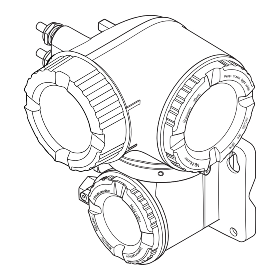
Endress+Hauser Hart Proline Promag P 500 Operating Instructions Manual (282 pages)
Coriolis flowmeter
Brand:
Endress+Hauser
| Category:
Measuring Instruments
| Size: 8 MB
Table of Contents
Table of Contents
3
About this Document
6
Document Function
6
Symbols
6
Safety Symbols
6
Electrical Symbols
6
Communication-Specific Symbols
6
Tool Symbols
7
Symbols for Certain Types of Information
7
Symbols in Graphics
7
Documentation
8
Registered Trademarks
8
Safety Instructions
9
Requirements for the Personnel
9
Intended Use
9
Workplace Safety
10
Operational Safety
10
Product Safety
10
Security
10
Device-Specific IT Security
11
Protecting Access Via Hardware Write Protection
11
Protecting Access Via a Password
11
Infrastructure Mode
12
Access Via Web Server
12
Access Via Service Interface (CDI-RJ45)
12
Product Description
13
Product Design
13
Proline 500 - Digital
13
Proline 500
13
Incoming Acceptance and Product
15
Identification
15
Incoming Acceptance
15
Product Identification
15
Transmitter Nameplate
16
Sensor Nameplate
18
Symbols on the Device
19
Storage and Transport
20
Storage Conditions
20
Transporting the Product
20
Measuring Devices Without Lifting Lugs
20
Measuring Devices with Lifting Lugs
21
Transporting with a Fork Lift
21
Packaging Disposal
21
Installation
21
Mounting Requirements
21
Installation Position
21
Inlet and Outlet Runs
23
Installation Dimensions
23
Environmental and Process Requirements
24
Ambient Temperature Range
24
Static Pressure
24
Thermal Insulation
24
Special Installation Instructions
26
Hygienic Compatibility
26
Installing the Measuring Instrument
28
Required Tools
28
Preparing the Measuring Instrument
28
Mounting the Measuring Device
29
Mounting the Transmitter Housing: Proline 500 - Digital
29
Wall Mounting
30
Drill the Holes
30
Mounting the Transmitter Housing: Proline 500
31
Turning the Transmitter Housing: Proline 500
32
Turning the Display Module: Proline 500
32
Post-Installation Check
33
Electrical Connection
34
Electrical Safety
34
Connecting Requirements
34
Required Tools
34
Requirements for Connection Cable
34
Terminal Assignment
39
Shielding and Grounding
39
Preparing the Measuring Device
40
Connecting the Measuring Instrument: Proline 500 - Digital
42
Connecting the Connecting Cable
42
Connecting the Signal Cable and the Supply Voltage Cable
47
Connecting the Measuring Instrument: Proline 500
49
Fitting the Connecting Cable
49
Potential Equalization
52
Requirements
52
Special Connection Instructions
53
Connection Examples
53
Current Output 4-20 Ma
53
Pulse/Frequency Output
54
Switch Output
54
Relay Output
55
Current Input
55
Status Input
55
Hardware Settings
56
Setting the Device Address
56
Activating the Terminating Resistor
57
Activating the Default IP Address
58
Ensuring the Degree of Protection
60
Post-Connection Check
60
Operation Options
61
Overview of Operation Options
61
Structure and Function of the Operating Menu
62
Structure of the Operating Menu
62
Operating Philosophy
63
Access to Operating Menu Via Local Display
64
Operational Display
64
Status Signals
64
Display Area
65
Measured Variables
65
Navigation View
67
Navigation Path
67
Locking Procedure
68
Editing View
69
Numeric Editor
69
Text Editor
69
Operating Elements
71
Opening the Context Menu
71
Navigating and Selecting from List
73
Calling the Parameter Directly
73
Calling up Help Text
74
Changing the Parameters
74
User Roles and Related Access Authorization
75
Disabling Write Protection Via Access Code
75
Enabling and Disabling the Keypad
76
Access to Operating Menu Via Web Browser
76
Function Range
76
Requirements
77
Connecting the Device
78
Logging on
80
User Interface
81
Function Row
81
Disabling the Web Server
82
Logging out
82
Access to the Operating Menu Via the Operating Tool
83
Connecting the Operating Tool
83
Service Interface
83
Fieldcare
86
Devicecare
87
System Integration
89
Overview of Device Description Files
89
Current Version Data for the Device
89
Operating Tools
89
Device Master File (GSD)
89
Manufacturer-Specific GSD
90
Profile GSD
90
Compatibility with Earlier Model
90
Automatic Identification (Factory Setting)
91
Manual Setting
91
Replacing the Measuring Devices Without Changing the GSD File or Restarting the Controller
91
Using the GSD Modules of the Previous Model
92
Using the CONTROL_BLOCK Module in the Previous Model
92
Cyclic Data Transmission
93
Block Model
93
Description of the Modules
93
AI Module (Analog Input)
94
TOTAL Module
95
Factory Setting
96
Data Structure
96
EMPTY_MODULE Module
99
Address Shifting Configuration
100
Function Description
100
Structure
100
Configuring Address Shifting
101
Accessing Data Via PROFIBUS DP
101
Commissioning
103
Post-Mounting and Post-Connection Check
103
Switching on the Measuring Device
103
Connecting Via Fieldcare
103
Configuring the Device Address Via Software
103
PROFIBUS Network
103
Setting the Operating Language
103
Configuring the Measuring Instrument
104
Defining the Tag Name
105
Endress+Hauser
105
Setting the System Units
106
Parameter Overview with Brief Description
107
Selecting and Setting the Medium
109
Interface
109
Configuration of the Analog Inputs
111
10.6.6 Displaying the I/O Configuration
112
Configuring the Current Input
113
Configuring the Status Input
114
Configuring the Current Output
114
10.6.10 Configuring the Pulse/Frequency/Switch Output
118
10.6.11 Configuring the Relay Output
125
10.6.12 Configuring the Local Display
127
10.6.13 Configuring the Low Flow Cut off
130
Configuring Partially Filled Pipe
131
Advanced Settings
132
Calculated Process Variables
133
Carrying out a Sensor Adjustment
134
Density Adjustment
135
Configuring the Totalizer
140
Carrying out Additional Display Configurations
142
WLAN Configuration
145
Configuration Management
146
Function Scope of the "Configuration Management" Parameter
147
Using Parameters for Device Administration
147
Simulation
149
Protecting Settings from Unauthorized Access
151
Write Protection Via Access Code
152
Write Protection Via Write Protection Switch
153
Operation
156
Reading off the Device Locking Status
156
Adjusting the Operating Language
156
Configuring the Display
156
Reading off Measured Values
156
Measured Variables" Submenu
157
Totalizer
159
Input Values" Submenu
160
Output Values
161
Adapting the Measuring Device to the Process Conditions
163
Performing a Totalizer Reset
163
Displaying the Measured Value History
164
Diagnostics and Troubleshooting
168
General Troubleshooting
168
Diagnostic Information Via Light Emitting Diodes
171
Transmitter
171
Sensor Connection Housing
173
Diagnostic Information on Local Display
174
Diagnostic Message
174
Diagnostic Information
175
Calling up Remedial Measures
176
Diagnostic Information in the Web Browser
176
Diagnostic Options
176
Calling up Remedy Information
177
Diagnostic Information in Fieldcare or Devicecare
177
Diagnostic Options
177
Calling up Remedy Information
178
Adapting the Diagnostic Information
179
Adapting the Diagnostic Behavior
179
Overview of Diagnostic Information
182
Diagnostic of Sensor
182
Diagnostic of Electronic
189
Diagnostic of Configuration
206
Diagnostic of Process
220
Pending Diagnostic Events
233
Diagnostics List
233
12.10 Event Logbook
234
12.10.1 Reading out the Event Logbook
234
Information Events
234
12.10.2 Filtering the Event Logbook
235
12.10.3 Overview of Information Events
235
12.11 Resetting the Measuring Device
236
12.11.1 Function Range of "Device Reset" Parameter
236
12.12 Device Information
237
12.13 Firmware History
239
Maintenance
240
Maintenance Work
240
Exterior Cleaning
240
Internal Cleaning
240
Measuring and Test Equipment
240
Endress+Hauser Services
240
Repair
241
General Notes
241
Repair and Conversion Concept
241
Notes for Repair and Conversion
241
Spare Parts
241
Endress+Hauser Services
241
Return
241
Disposal
242
Removing the Measuring Device
242
Disposing of the Measuring Device
242
Accessories
243
Device-Specific Accessories
243
For the Transmitter
243
For the Sensor
244
Service-Specific Accessories
244
System Components
245
Technical Data
246
Application
246
Function and System Design
246
Input
247
Direct Measured Variables
247
Output
249
Output Signal
249
Power Supply
254
Performance Characteristics
256
Accuracy of Outputs
257
Mounting
260
Environment
260
Process
261
16.10 Mechanical Construction
263
Window Material
264
Measuring Tubes
265
Surface Roughness
266
Process Connection Materials
266
16.11 User Interface
267
Historom Data Management
269
16.12 Certificates and Approvals
270
16.13 Application Packages
272
Heartbeat Verification
273
Heartbeat Monitoring
273
16.14 Accessories
274
16.15 Supplemental Documentation
274
Technical Information
274
Description of Device Parameters
274
Special Documentation
275
Installation Instructions
275
Index
276
Advertisement
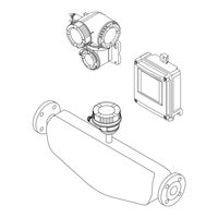
Endress+Hauser Hart Proline Promag P 500 Operating Instructions Manual (252 pages)
Electromagnetic flowmeter
Brand:
Endress+Hauser
| Category:
Measuring Instruments
| Size: 12 MB
Table of Contents
Table of Contents
3
1 About this Document
6
Document Function
6
Symbols
6
Safety Symbols
6
Electrical Symbols
6
Communication Symbols
6
Tool Symbols
7
Symbols for Certain Types of Information
7
Symbols in Graphics
7
Documentation
8
Standard Documentation
8
Supplementary Device-Dependent Documentation
8
Registered Trademarks
8
2 Safety Instructions
9
Requirements for the Personnel
9
Designated Use
9
Workplace Safety
10
Operational Safety
10
Product Safety
10
Security
11
Device-Specific IT Security
11
Protecting Access Via Hardware Write Protection
11
Protecting Access Via a Password
11
Access Via Web Server
12
Access Via Service Interface (CDI-RJ45)
13
3 Product Description
14
Product Design
14
Proline 500 - Digital
14
Proline 500
14
4 Incoming Acceptance and Product
16
Identification
16
Incoming Acceptance
16
Product Identification
16
Transmitter Nameplate
17
Sensor Nameplate
19
Symbols on Measuring Device
20
5 Storage and Transport
21
Storage Conditions
21
Transporting the Product
21
Measuring Devices Without Lifting Lugs
21
Measuring Devices with Lifting Lugs
22
Transporting with a Fork Lift
22
Packaging Disposal
22
6 Installation
23
Installation Conditions
23
Mounting Position
23
Environment and Process Requirements
25
Special Mounting Instructions
28
Mounting the Measuring Device
28
Required Tools
28
Preparing the Measuring Device
29
Mounting the Sensor
29
Mounting the Transmitter Housing: Proline 500 - Digital
33
Mounting the Transmitter Housing: Proline 500
35
Turning the Transmitter Housing: Proline 500
36
Turning the Display Module: Proline 500
37
Post-Installation Check
37
7 Electrical Connection
38
Connection Conditions
38
Required Tools
38
Requirements for Connecting Cable
38
Terminal Assignment
42
Device Plugs Available
43
Pin Assignment of Device Plug
43
Preparing the Measuring Device
43
Preparing the Connecting Cable: Proline 500 - Digital
44
Preparing the Connecting Cable: Proline 500
44
Connecting the Measuring Device: Proline 500 - Digital
46
Connecting the Connecting Cable
46
Connecting the Transmitter
49
Integrating the Transmitter into a Network
52
Connecting the Measuring Device: Proline 500
54
Connecting the Connecting Cable
54
Connecting the Transmitter
57
Integrating the Transmitter into a Network
60
Ensuring Potential Equalization
61
Requirements
61
Connection Example, Standard Scenario
62
Connection Example in Special Situations
62
Special Connection Instructions
64
Connection Examples
64
Hardware Settings
67
Setting the Device Name
67
Activating the Default IP Address
70
Ensuring the Degree of Protection
71
Post-Connection Check
72
8 Operation Options
73
Overview of Operation Options
73
Structure and Function of the Operating
74
Structure of the Operating Menu
74
Operating Philosophy
75
Access to the Operating Menu Via the Local Display
76
Operational Display
76
Navigation View
77
Editing View
79
Operating Elements
81
Opening the Context Menu
81
Navigating and Selecting from List
83
Calling the Parameter Directly
83
Calling up Help Text
84
Changing the Parameters
84
User Roles and Related Access Authorization
85
Disabling Write Protection Via Access
85
Code
85
Enabling and Disabling the Keypad
86
Access to the Operating Menu Via the Web Browser
86
Function Range
86
Prerequisites
87
Establishing a Connection
88
Logging on
90
User Interface
91
Disabling the Web Server
92
Logging out
93
Access to the Operating Menu Via the Operating Tool
93
Connecting the Operating Tool
93
Fieldcare
97
Devicecare
98
9 System Integration
99
Overview of Device Description Files
99
Current Version Data for the Device
99
Operating Tools
99
Device Master File (GSD)
99
File Name of the Device Master File (GSD)
100
Cyclic Data Transmission
101
Overview of the Modules
101
Description of the Modules
101
Status Coding
107
Factory Setting
108
Startup Configuration
108
System Redundancy S2
109
10 Commissioning
110
Function Check
110
Switching on the Measuring Device
110
Connecting Via Fieldcare
110
Setting the Operating Language
110
Configuring the Measuring Device
111
Defining the Tag Name
112
Setting the System Units
112
Displaying the Communication
114
Interface
114
Selecting and Setting the Medium
115
Displaying the I/O Configuration
115
Configuring the Current Input
116
Configuring the Status Input
117
Configuring the Current Output
118
Configuring the Pulse/Frequency
121
Switch Output
121
10.5.10 Configuring the Relay Output
127
10.5.11 Configuring the Local Display
129
10.5.12 Configuring the Low Flow Cut off
132
10.5.13 Configuring Empty Pipe Detection
134
Advanced Settings
135
Using the Parameter to Enter the Access Code
136
Carrying out a Sensor Adjustment
136
Configuring the Totalizer
136
Carrying out Additional Display Configurations
138
Performing Electrode Cleaning
142
WLAN Configuration
143
Configuration Management
145
Using Parameters for Device Administration
146
Simulation
148
Protecting Settings from Unauthorized
151
Access
151
Write Protection Via Write Protection
152
Switch
152
11 Operation
155
Reading the Device Locking Status
155
Adjusting the Operating Language
155
Configuring the Display
155
Reading Measured Values
155
Process Variables" Submenu
156
Totalizer
156
Input Values" Submenu
157
Output Values
159
Adapting the Measuring Device to the Process
161
Conditions
161
Performing a Totalizer Reset
161
Function Scope of the "Control Totalizer" Parameter
161
Function Scope of the "Reset All Totalizers" Parameter
162
Showing Data Logging
162
12 Diagnostics and Troubleshooting
166
General Troubleshooting
166
Diagnostic Information Via Light Emitting
169
Diodes
169
Transmitter
169
Sensor Connection Housing
171
Diagnostic Information on Local Display
173
Diagnostic Message
173
Calling up Remedial Measures
175
Diagnostic Information in the Web Browser
175
Diagnostic Options
175
Calling up Remedy Information
176
Diagnostic Information in Fieldcare or Devicecare
176
Diagnostic Options
176
Calling up Remedy Information
177
Adapting the Diagnostic Information
178
Adapting the Diagnostic Behavior
178
Overview of Diagnostic Information
181
Diagnostic of Sensor
181
Diagnostic of Electronic
184
Diagnostic of Configuration
193
Diagnostic of Process
201
Pending Diagnostic Events
205
Diagnostic List
205
12.10 Event Logbook
206
12.10.1 Reading out the Event Logbook
206
12.10.2 Filtering the Event Logbook
207
12.10.3 Overview of Information Events
207
12.11 Resetting the Measuring Device
208
12.11.1 Function Scope of the "Device Reset" Parameter
208
12.12 Device Information
209
12.13 Firmware History
210
13 Maintenance
211
Maintenance Tasks
211
Exterior Cleaning
211
Interior Cleaning
211
Replacing Seals
211
Measuring and Test Equipment
211
Endress+Hauser Services
211
14 Repair
212
General Notes
212
Repair and Conversion Concept
212
Notes for Repair and Conversion
212
Spare Parts
212
Endress+Hauser Services
212
Return
212
Disposal
212
Removing the Measuring Device
212
Disposing of the Measuring Device
213
15 Accessories
214
Device-Specific Accessories
214
For the Transmitter
214
For the Sensor
215
Communication-Specific Accessories
215
Service-Specific Accessories
216
System Components
217
16 Technical Data
218
Application
218
Function and System Design
218
Input
218
Output
222
Power Supply
227
Performance Characteristics
228
Installation
229
Environment
229
Process
230
16.10 Mechanical Construction
233
16.11 Human Interface
238
16.12 Certificates and Approvals
241
16.13 Application Packages
243
16.14 Accessories
244
16.15 Supplementary Documentation
244
Index
246
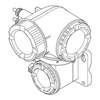
Endress+Hauser Hart Proline Promag P 500 Operating Instructions Manual (210 pages)
Electromagnetic flowmeter
Brand:
Endress+Hauser
| Category:
Measuring Instruments
| Size: 10 MB
Table of Contents
Table of Contents
3
1 About this Document
6
Document Function
6
Symbols Used
6
Safety Symbols
6
Electrical Symbols
6
Communication Symbols
6
Tool Symbols
7
Symbols for Certain Types of Information
7
Symbols in Graphics
7
Documentation
8
Standard Documentation
8
Supplementary Device-Dependent Documentation
8
Registered Trademarks
8
2 Basic Safety Instructions
9
Requirements for the Personnel
9
Designated Use
9
Workplace Safety
10
Operational Safety
10
Product Safety
10
IT Security
11
Device-Specific IT Security
11
Protecting Access Via Hardware Write Protection
11
Protecting Access Via a Password
11
Access Via Fieldbus
12
Access Via Web Server
12
Access Via CDI-RJ45 Service Interface
12
3 Product Description
14
Product Design
14
Proline 500 - Digital
14
Proline 500
14
4 Incoming Acceptance and Product
16
Identification
16
Incoming Acceptance
16
Product Identification
16
Transmitter Nameplate
17
Sensor Nameplate
19
Symbols on Measuring Device
20
5 Storage and Transport
21
Storage Conditions
21
Transporting the Product
21
Measuring Devices Without Lifting Lugs
21
Measuring Devices with Lifting Lugs
22
Transporting with a Fork Lift
22
Packaging Disposal
22
6 Installation
23
Installation Conditions
23
Mounting Position
23
Requirements from Environment and Process
26
Special Mounting Instructions
28
Mounting the Measuring Device
28
Required Tools
28
Preparing the Measuring Device
29
Mounting the Sensor
29
Mounting the Transmitter Housing: Proline 500 - Digital
33
Mounting the Transmitter Housing: Proline 500
35
Turning the Transmitter Housing: Proline 500
36
Turning the Display Module: Proline 500
37
Post-Installation Check
37
7 Electrical Connection
38
Connection Conditions
38
Required Tools
38
Requirements for Connecting Cable
38
Terminal Assignment
41
Preparing the Measuring Device
42
Preparing the Connecting Cable: Proline 500 - Digital
43
Preparing the Connecting Cable: Proline 500
43
Connecting the Measuring Device: Proline 500 - Digital
45
Connecting the Connecting Cable
45
Connecting the Signal Cable and the Supply Voltage Cable
48
Connecting the Measuring Device: Proline 500
50
Connecting the Connecting Cable
50
Connecting the Signal Cable and the Supply Voltage Cable
53
Ensure Potential Equalization
55
Requirements
55
Connection Example, Standard Scenario
55
Connection Example in Special Situations
55
Special Connection Instructions
57
Connection Examples
57
Ensuring the Degree of Protection
61
Post-Connection Check
62
8 Operation Options
63
Overview of Operation Options
63
Structure and Function of the Operating
64
Structure of the Operating Menu
64
Operating Philosophy
65
Access to the Operating Menu Via the Local Display
66
Operational Display
66
Navigation View
67
Editing View
69
Operating Elements
71
Opening the Context Menu
71
Navigating and Selecting from List
73
Calling the Parameter Directly
73
Calling up Help Text
74
Changing the Parameters
74
User Roles and Related Access Authorization
75
Disabling Write Protection Via Access
75
Code
75
Enabling and Disabling the Keypad
76
Access to the Operating Menu Via the Web Browser
76
Function Range
76
Prerequisites
77
Establishing a Connection
78
Logging on
80
User Interface
81
Disabling the Web Server
82
Logging out
82
Access to the Operating Menu Via the Operating Tool
82
Connecting the Operating Tool
83
Field Xpert SFX350, SFX370
86
Fieldcare
86
Devicecare
88
AMS Device Manager
88
Simatic Pdm
89
Field Communicator 475
89
9 System Integration
90
Overview of Device Description Files
90
Current Version Data for the Device
90
Operating Tools
90
Measured Variables Via HART Protocol
90
Other Settings
92
10 Commissioning
94
Function Check
94
Switching on the Measuring Device
94
Setting the Operating Language
94
Configuring the Measuring Device
94
Defining the Tag Name
96
Setting the System Units
96
Displaying the I/O Configuration
98
Configuring the Status Input
98
Configuring the Current Input
99
Configuring the Current Output
100
Configuring the Pulse/Frequency
103
Switch Output
103
Configuring the Local Display
109
Configuring the Low Flow Cut off
111
10.4.10 Configuring Empty Pipe Detection
112
10.4.11 Configuring the HART Input
112
10.4.12 Configuring the Relay Output
114
10.4.13 Configuring the Double Pulse Output
116
Advanced Settings
118
Using the Parameter to Enter the Access Code
119
Carrying out a Sensor Adjustment
119
Configuring the Totalizer
119
Carrying out Additional Display Configurations
121
Performing Electrode Cleaning
124
WLAN Configuration
125
Configuration Management
126
Using Parameters for Device Administration
127
Simulation
129
Protecting Settings from Unauthorized
132
Access
132
Write Protection Via Write Protection
134
Switch
134
11 Operation
136
Reading the Device Locking Status
136
Adjusting the Operating Language
136
Configuring the Display
136
Reading Measured Values
136
Process Variables" Submenu
136
Totalizer" Submenu
138
Input Values" Submenu
138
Output Values
139
Adapting the Measuring Device to the Process
142
Conditions
142
Performing a Totalizer Reset
142
Function Scope of the "Control Totalizer" Parameter
142
Function Scope of the "Reset All Totalizers" Parameter
143
Showing Data Logging
143
12 Diagnostics and Troubleshooting
146
General Troubleshooting
146
12.2 Diagnostic Information Via Light Emitting
148
Diodes
148
Transmitter
148
Sensor Connection Housing
150
Diagnostic Information on Local Display
152
Diagnostic Message
152
Calling up Remedial Measures
154
Diagnostic Information in the Web Browser
154
Diagnostic Options
154
Calling up Remedy Information
155
Diagnostic Information in Devicecare or
156
Fieldcare
156
Diagnostic Options
156
Calling up Remedy Information
157
Adapting the Diagnostic Information
157
Adapting the Diagnostic Behavior
157
Adapting the Status Signal
157
Overview of Diagnostic Information
158
Pending Diagnostic Events
162
Diagnostic List
163
12.10 Event Logbook
163
12.10.1 Reading out the Event Logbook
163
12.10.2 Filtering the Event Logbook
164
12.10.3 Overview of Information Events
164
12.11 Resetting the Measuring Device
166
12.11.1 Function Scope of the "Device Reset" Parameter
166
12.12 Device Information
166
12.13 Firmware History
169
13 Maintenance
170
Maintenance Tasks
170
Exterior Cleaning
170
Interior Cleaning
170
Replacing Seals
170
Measuring and Test Equipment
170
Endress+Hauser Services
170
14 Repairs
171
General Notes
171
Repair and Conversion Concept
171
Notes for Repair and Conversion
171
Spare Parts
171
Endress+Hauser Services
171
Return
171
Disposal
172
Removing the Measuring Device
172
Disposing of the Measuring Device
172
15 Accessories
173
Device-Specific Accessories
173
For the Transmitter
173
For the Sensor
174
Communication-Specific Accessories
174
Service-Specific Accessories
175
System Components
175
16 Technical Data
176
Application
176
Function and System Design
176
Input
176
Output
179
Power Supply
184
Performance Characteristics
185
Installation
186
Environment
186
Process
187
16.10 Mechanical Construction
190
16.11 Operability
195
16.12 Certificates and Approvals
199
16.13 Application Packages
201
16.14 Accessories
202
Supplementary Documentation
202
Index
204
Advertisement
Endress+Hauser Hart Proline Promag P 500 Special Documentation (52 pages)
Brand:
Endress+Hauser
| Category:
Industrial Equipment
| Size: 4 MB
Table of Contents
Table of Contents
3
Manufacturer's Declaration
4
Certificate
5
About this Document
6
Document Function
6
Content and Scope
6
Symbols
6
Documentation
7
Registered Trademarks
7
Product Features and Availability
8
Product Features
8
Availability
8
System Integration
10
Automated Data Exchange
11
Data Exchange Performed by the User (Asset Management System)
12
Data Management
12
Heartbeat Verification
19
Performance Characteristics
19
Commissioning
19
Operation
20
Heartbeat Monitoring
46
Commissioning
46
Operation
47
Advertisement
Related Products
Endress+Hauser Proline Prowirl 73
Endress+Hauser Proline Promass 80F
Endress+Hauser Prosonic Flow 500-digital
Endress+Hauser Proline Promass 40
Endress+Hauser PROFIBUS-PA
Endress+Hauser promag 50 PROFIBUS-PA
Endress+Hauser Proline Promass F 200 FOUNDATION Fieldbus
Endress+Hauser Promag 100
Endress+Hauser Proline Promass P 500 PROFIBUS DP
Endress+Hauser Prosonic Flow P 500
Endress+Hauser Categories
Measuring Instruments
Transmitter
Radar
Switch
Accessories
More Endress+Hauser Manuals
Login
Sign In
OR
Sign in with Facebook
Sign in with Google
Upload manual
Upload from disk
Upload from URL