Endress+Hauser Proline Promass X 500 PROFINET Operating Instructions Manual
Coriolis flowmeter
Hide thumbs
Also See for Proline Promass X 500 PROFINET:
- Operating instructions manual (232 pages) ,
- Operating instructions manual (282 pages)

Related Manuals for Endress+Hauser Proline Promass X 500 PROFINET


Summary of Contents for Endress+Hauser Proline Promass X 500 PROFINET
- Page 1 Products Solutions Services BA01768D/06/EN/04.24-00 71675220 2024-11-01 Valid as of version 01.01.zz (Device firmware) Operating Instructions Proline Promass X 500 PROFINET Coriolis flowmeter...
- Page 2 • The manufacturer reserves the right to modify technical data without prior notice. Your Endress+Hauser sales organization will supply you with current information and updates to this manual. Endress+Hauser...
- Page 3 Proline Promass X 500 PROFINET Table of contents Table of contents About this document ....6 Installation ..... . . 22 Document function .
- Page 4 Table of contents Proline Promass X 500 PROFINET Structure and function of the operating 10.5.2 Displaying the communication menu ......
- Page 5 13.2 Measuring and test equipment ... 256 13.3 Endress+Hauser services ....256 Repair ......257 14.1 General notes .
- Page 6 About this document Proline Promass X 500 PROFINET About this document Document function These Operating Instructions contain all the information required in the various life cycle phases of the device: from product identification, incoming acceptance and storage, to installation, connection, operation and commissioning, through to troubleshooting, maintenance and disposal.
- Page 7 Proline Promass X 500 PROFINET About this document 1.2.4 Tool symbols Symbol Meaning Torx screwdriver Phillips head screwdriver Open-ended wrench 1.2.5 Symbols for certain types of information Symbol Meaning Permitted Procedures, processes or actions that are permitted. Preferred Procedures, processes or actions that are preferred.
- Page 8 • Device Viewer (www.endress.com/deviceviewer): Enter the serial number from the nameplate • Endress+Hauser Operations app: Enter serial number from nameplate or scan matrix code on nameplate. The following documentation may be available depending on the device version ordered: Document type...
- Page 9 Proline Promass X 500 PROFINET Safety instructions Safety instructions Requirements for the personnel The personnel for installation, commissioning, diagnostics and maintenance must fulfill the following requirements: ‣ Trained, qualified specialists must have a relevant qualification for this specific function and task.
- Page 10 Verification for borderline cases: ‣ For special fluids and fluids for cleaning, Endress+Hauser is glad to provide assistance in verifying the corrosion resistance of fluid-wetted materials, but does not accept any warranty or liability as minute changes in the temperature, concentration or level of contamination in the process can alter the corrosion resistance properties.
- Page 11 Proline Promass X 500 PROFINET Safety instructions IT security The manufacturer warranty is valid only if the product is installed and used as described in the Operating Instructions. The product is equipped with security mechanisms to protect it against any inadvertent changes to the settings.
- Page 12 Safety instructions Proline Promass X 500 PROFINET User-specific access code Write access to the device parameters via the local display, web browser or operating tool (e.g. FieldCare, DeviceCare) can be protected by the modifiable, user-specific access code (→ 159).
- Page 13 Proline Promass X 500 PROFINET Safety instructions This includes organizational security measures such as the assignment of access authorization as well as technical measures such as network segmentation. Transmitters with an Ex de approval may not be connected via the service interface (CDI-RJ45)! Order code for "Approval transmitter + sensor", options (Ex de): BA, BB, C1, C2, GA,...
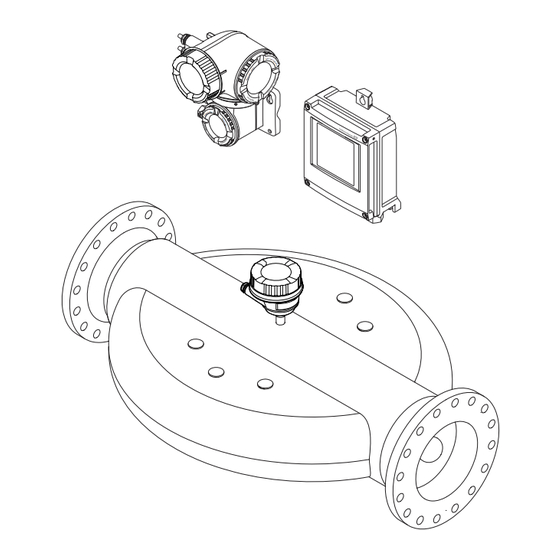
- Page 14 Product description Proline Promass X 500 PROFINET Product description The measuring system consists of a transmitter and a sensor. The transmitter and sensor are mounted in physically separate locations. They are interconnected by connecting cables. Product design Two versions of the transmitter are available.
- Page 15 Proline Promass X 500 PROFINET Product description 3.1.2 Proline 500 Signal transmission: analog Order code for "Integrated ISEM electronics", option B "Transmitter" For use in applications required to meet special requirements due to ambient or operating conditions. As the electronics are located in the transmitter, the device is ideal in the event of: •...
- Page 16 • Enter the serial numbers from the nameplates in the Device Viewer (www.endress.com/deviceviewer): all the information about the device is displayed. • Enter the serial numbers from the nameplates into the Endress+Hauser Operations app or scan the DataMatrix code on the nameplate with the Endress+Hauser Operations app: all the information about the device is displayed.
- Page 17 Proline Promass X 500 PROFINET Incoming acceptance and product identification 4.2.1 Transmitter nameplate Proline 500 – digital Order code: Ser. no.: Ext. ord. cd.: Date: A0029194 3 Example of a transmitter nameplate Name of the transmitter Manufacturer address/certificate holder...
- Page 18 Incoming acceptance and product identification Proline Promass X 500 PROFINET Proline 500 3 4 5 Order code: Ser. no.: Ext. ord. cd.: Date: A0029192 4 Example of a transmitter nameplate Manufacturer address/certificate holder Name of the transmitter Order code Serial number (Ser.
- Page 19 Proline Promass X 500 PROFINET Incoming acceptance and product identification 4.2.2 Sensor nameplate Order code: Ser. no.: Ext. ord. cd.: Date: A0029199 5 Example of a sensor nameplate Name of the sensor Manufacturer address/certificate holder Order code Serial number (Ser. no.) Extended order code (Ext.
- Page 20 Incoming acceptance and product identification Proline Promass X 500 PROFINET 4.2.3 Symbols on the device Symbol Meaning WARNING! This symbol alerts you to a dangerous situation. Failure to avoid this situation can result in serious or fatal injury. Please consult the documentation for the measuring instrument to discover the type of potential danger and measures to avoid it.
- Page 21 Proline Promass X 500 PROFINET Storage and transport Storage and transport Storage conditions Observe the following notes for storage: ‣ Store in the original packaging to ensure protection from shock. ‣ Do not remove protective covers or protective caps installed on process connections.
- Page 22 Installation Proline Promass X 500 PROFINET 5.2.2 Measuring devices with lifting lugs CAUTION Special transportation instructions for devices with lifting lugs ‣ Only use the lifting lugs fitted on the device or flanges to transport the device. ‣ The device must always be secured at two lifting lugs at least.
- Page 23 Proline Promass X 500 PROFINET Installation Installation in down pipes However, the following installation suggestion allows for installation in an open vertical pipeline. Pipe restrictions or the use of an orifice with a smaller cross-section than the nominal diameter prevent the sensor running empty while measurement is in progress.
- Page 24 Installation Proline Promass X 500 PROFINET Orientation Recommendation Horizontal orientation, transmitter at bottom → 7, 24 A0015590 Horizontal orientation, transmitter at → 7, 24 side A0015592 This orientation is recommended to ensure self-draining. Applications with low process temperatures may reduce the ambient temperature. To maintain the minimum ambient temperature for the transmitter, this orientation is recommended.
- Page 25 Proline Promass X 500 PROFINET Installation 6.1.2 Environmental and process requirements Ambient temperature range Measuring device • –40 to +60 °C (–40 to +140 °F) • Order code for "Test, certificate", option JP: –50 to +60 °C (–58 to +140 °F) •...
- Page 26 Installation Proline Promass X 500 PROFINET NOTICE Electronics overheating on account of thermal insulation! ‣ Recommended orientation: horizontal orientation, sensor connection housing pointing downwards. ‣ Do not insulate the sensor connection housing. ‣ Maximum permissible temperature at the lower end of the sensor connection housing: 80 °C (176 °F)
- Page 27 Proline Promass X 500 PROFINET Installation Vibrations The high oscillation frequency of the measuring tubes ensures that the correct operation of the measuring system is not influenced by plant vibrations. 6.1.3 Special mounting instructions Drainability When installed vertically, the measuring tubes can be drained completely and protected against buildup.
- Page 28 Installation Proline Promass X 500 PROFINET RUPTURE DISK A0029944 Rupture disk label Rupture disk with 1/2" NPT internal thread and 1" width across flats Transportation guard For information on the dimensions, see the "Technical Information" document, "Mechanical construction" section (accessories).
- Page 29 Proline Promass X 500 PROFINET Installation Weather protection cover 213 (8.4) 203 (8.0) A0029552 9 Weather protection cover for Proline 500 – digital; engineering unit mm (in) 280 (11.0) 255 (10.0) 146 (5.75) 134 (5.3) 12 (0.47) 30 (1.18) A0029553 ...
- Page 30 Installation Proline Promass X 500 PROFINET SW 2.5 5 (0.2) min. 15 (0.6) A0029799 Cover borehole for the securing screw Securing screw to lock the cover Installing the measuring instrument 6.2.1 Required tools For transmitter For mounting on a post: •...
- Page 31 Proline Promass X 500 PROFINET Installation 2. Install the measuring device or turn the transmitter housing so that the cable entries do not point upwards. A0029263 6.2.4 Mounting the transmitter housing: Proline 500 – digital CAUTION Ambient temperature too high! Danger of electronics overheating and housing deformation.
- Page 32 Installation Proline Promass X 500 PROFINET ø TX 25 20…70 ø ( 0.79…2.75) SW 10 A0029051 11 Unit mm (in) Wall mounting Required tools: Drill with drill bit ⌀ 6.0 mm 17 (0.67) 5.8 (0.23) 5.8 (0.23) 149 (5.85) A0029054 ...
- Page 33 Proline Promass X 500 PROFINET Installation 5. Tighten the fixing screws. 6.2.5 Mounting the transmitter housing: Proline 500 CAUTION Ambient temperature too high! Danger of electronics overheating and housing deformation. ‣ Do not exceed the permitted maximum ambient temperature. ‣...
- Page 34 Installation Proline Promass X 500 PROFINET WARNING Order code for "Transmitter housing", option L "Cast, stainless": cast transmitters are very heavy. They are unstable if they are not mounted on a secure, fixed post. ‣ Only mount the transmitter on a secure, fixed post on a stable surface.
- Page 35 Proline Promass X 500 PROFINET Installation – – – 3 mm A0030035 1. Depending on the device version: Loosen the securing clamp of the connection compartment cover. 2. Unscrew the connection compartment cover. 3. Turn the display module to the desired position: max. 8 × 45° in each direction.
- Page 36 Electrical connection Proline Promass X 500 PROFINET Electrical connection WARNING Live parts! Incorrect work performed on the electrical connections can result in an electric shock. ‣ Set up a disconnecting device (switch or power-circuit breaker) to easily disconnect the device from the supply voltage.
- Page 37 Proline Promass X 500 PROFINET Electrical connection Ethernet-APL Shielded twisted-pair cable. Cable type A is recommended. https://www.profibus.com Ethernet-APL White Paper " Current output 0 /4 to 20 mA (excluding HART) Standard installation cable is sufficient. Pulse /frequency /switch output Standard installation cable is sufficient.
- Page 38 Electrical connection Proline Promass X 500 PROFINET A0032476 Proline 500 digital transmitter Proline 500 transmitter Sensor Promass Non-hazardous area Hazardous area: Zone 2; Class I, Division 2 Hazardous area: Zone 1; Class I, Division 1 Standard cable to 500 digital transmitter → 38 Transmitter installed in the non-hazardous area or hazardous area: Zone 2;...
- Page 39 Proline Promass X 500 PROFINET Electrical connection Cross-section Cable length [max.] 1.00 mm (AWG 17) 240 m (720 ft) 1.50 mm (AWG 15) 300 m (900 ft) Optionally available connecting cable Design 2 × 2 × 0.34 mm (AWG 22) PVC cable with common shield (2 pairs, uninsulated stranded CU wires;...
- Page 40 Electrical connection Proline Promass X 500 PROFINET Cross-section Cable length [max.] Termination 2 x 2 x 0.50 mm 50 m (150 ft) 2 x 2 x 0.50 mm (AWG 20) (AWG 20) BN WT YE GN • +, – = 0.5 mm •...
- Page 41 Proline Promass X 500 PROFINET Electrical connection C: Connecting cable between sensor and transmitter: Proline 500 Design 6 × 0.38 mm PVC cable with individual shielded cores and common copper shield With order code for "Test, certificate", option JQ 7 × 0.38 mm...
- Page 42 Electrical connection Proline Promass X 500 PROFINET Order code for "Input; output 1", option RA "PROFINET" Order code for Cable entry/connection "Electrical connection" L, N, P, U Connector M12 × 1 – 1) 2) 1) 2) 1) 2) 1) 2) Connector M12 ×...
- Page 43 Proline Promass X 500 PROFINET Electrical connection Connecting the measuring instrument: Proline 500 - digital NOTICE An incorrect connection compromises electrical safety! ‣ Only properly trained specialist staff may perform electrical connection work. ‣ Observe applicable federal/national installation codes and regulations.
- Page 44 Electrical connection Proline Promass X 500 PROFINET Connecting the sensor connection housing via terminals For the device version with the order code for "Sensor connection housing": Option L "Cast, stainless" 10 (0.4) 3 mm TX 20 TX 20 22 mm...
- Page 45 Proline Promass X 500 PROFINET Electrical connection Connecting the connecting cable to the transmitter TX 20 TX 20 10 (0.4) 22 mm 24 mm A0029597 1. Loosen the 4 fixing screws on the housing cover. 2. Open the housing cover.
- Page 46 Electrical connection Proline Promass X 500 PROFINET 7.3.2 Integrating the transmitter into a network This section only presents the basic options for integrating the device into a network. For information on the procedure to follow to connect the transmitter correctly → 43.
- Page 47 Proline Promass X 500 PROFINET Electrical connection Integrating into a ring topology The device is integrated via the terminal connection for signal transmission (output 1) and the connection to the service interface (CDI-RJ45). Note the following when connecting: • Recommended cable: CAT5e, CAT6 or CAT7, with shielded connector (e.g. brand: YAMAICHI ;...
- Page 48 Electrical connection Proline Promass X 500 PROFINET Connecting the measuring instrument: Proline 500 NOTICE An incorrect connection compromises electrical safety! ‣ Only properly trained specialist staff may perform electrical connection work. ‣ Observe applicable federal/national installation codes and regulations. ‣...
- Page 49 Proline Promass X 500 PROFINET Electrical connection Connecting the sensor connection housing via terminals For the device version with the order code for "Housing": Option L "Cast, stainless" 10 (0.4) 3 mm 22 mm 24 mm A0029612 1. Loosen the securing clamp of the housing cover.
- Page 50 Electrical connection Proline Promass X 500 PROFINET Attaching the connecting cable to the transmitter 10 (0.4) 3 mm 22 mm 24 mm A0029592 1. Loosen the securing clamp of the connection compartment cover. 2. Unscrew the connection compartment cover. 3. Push the cable through the cable entry. To ensure tight sealing, do not remove the sealing ring from the cable entry.
- Page 51 Proline Promass X 500 PROFINET Electrical connection 7.4.2 Connecting the transmitter A0026781 Terminal connection for supply voltage Terminal connection for signal transmission, input/output Terminal connection for signal transmission, input/output or terminal connection for network connection via service interface (CDI-RJ45) Protective earth (PE)
- Page 52 Electrical connection Proline Promass X 500 PROFINET 10 (0.4) mm (in) – A0029815 7. Push the cable through the cable entry. To ensure tight sealing, do not remove the sealing ring from the cable entry. 8. Strip the cable and cable ends and connect to terminals 26-27. In the case of stranded cables, also fit ferrules.
- Page 53 Proline Promass X 500 PROFINET Electrical connection 5. Firmly tighten the cable glands. This concludes the cable connection process. 6. Close the terminal cover. 7. Fit the display module holder in the electronics compartment. 8. Screw on the connection compartment cover.
- Page 54 Electrical connection Proline Promass X 500 PROFINET 7.4.3 Integrating the transmitter into a network This section only presents the basic options for integrating the device into a network. For information on the procedure to follow to connect the transmitter correctly → 48.
- Page 55 Proline Promass X 500 PROFINET Electrical connection Integrating into a ring topology The device is integrated via the terminal connection for signal transmission (output 1) and the connection to the service interface (CDI-RJ45). Note the following when connecting: • Recommended cable: CAT5e, CAT6 or CAT7, with shielded connector (e.g. brand: YAMAICHI ;...
- Page 56 Electrical connection Proline Promass X 500 PROFINET Special connection instructions 7.6.1 Connection examples PROFINET A0028767 17 Connection example for PROFINET Control system (e.g. PLC) Ethernet switch Observe cable specifications Device plug Transmitter PROFINET: MRP (Media Redundancy Protocol) A0027544 Control system (e.g. PLC) Ethernet switch Observe cable specifications →...
- Page 57 Proline Promass X 500 PROFINET Electrical connection PROFINET: system redundancy S2 A0039553 18 Connection example for system redundancy S2 Control system 1 (e.g. PLC) Synchronization of control systems Control system 2 (e.g. PLC) Industrial Ethernet Managed Switch Transmitter Current output 4-20 mA 4...20 mA...
- Page 58 Electrical connection Proline Promass X 500 PROFINET Pulse/frequency output 12345 A0028761 21 Connection example for pulse/frequency output (passive) Automation system with pulse/frequency input (e.g. PLC with 10 kΩ pull-up or pull-down resistor) Power supply Transmitter: observe input values → 266...
- Page 59 Proline Promass X 500 PROFINET Electrical connection Current input A0028915 24 Connection example for 4 to 20 mA current input Power supply Terminal box External measuring device (to read in pressure or temperature, for instance) Transmitter Status input A0028764 ...
- Page 60 Electrical connection Proline Promass X 500 PROFINET Setting the device name using the DIP switches The last part of the device name can be set using DIP switches 1-8. The address range is between 1 and 254 (factory setting: serial number of the device )
- Page 61 Proline Promass X 500 PROFINET Electrical connection 1 2 3 4 5 6 7 8 Name of Station A0034497 1. Loosen the 4 fixing screws on the housing cover. 2. Open the housing cover. 3. Fold open the terminal cover.
- Page 62 Electrical connection Proline Promass X 500 PROFINET 5. Reconnect the device to the power supply. The configured device address is used once the device is restarted. Setting the device name via the automation system DIP switches 1-8 must all be set to OFF (factory setting) or all be set to ON to be able to set the device name via the automation system.
- Page 63 Proline Promass X 500 PROFINET Electrical connection ‣ Disconnect the device from the power supply. A0034499 1. Depending on the housing version, loosen the securing clamp or fixing screw of the housing cover. 2. Depending on the housing version, unscrew or open the housing cover and disconnect the local display from the main electronics module where necessary .
- Page 64 Electrical connection Proline Promass X 500 PROFINET Are the installed cables strain-relieved and securely routed? Are all cable glands installed, securely tightened and leak-tight? Cable run with "water trap" → 63? Is the terminal assignment correct ? ...
- Page 65 Proline Promass X 500 PROFINET Operation options Operation options Overview of operation options A0034513 Local operation via display module Computer with web browser or operating tool (e.g. FieldCare, DeviceCare, AMS Device Manager, SIMATIC PDM) Field Xpert SFX350 or SFX370 Field Xpert SMT70 Mobile handheld terminal Automation system (e.g.
- Page 66 Operation options Proline Promass X 500 PROFINET Structure and function of the operating menu 8.2.1 Structure of the operating menu For an overview of the operating menu for experts: see the "Description of Device Parameters" document supplied with the device → 291...
- Page 67 Proline Promass X 500 PROFINET Operation options 8.2.2 Operating philosophy The individual parts of the operating menu are assigned to certain user roles (e.g. operator, maintenance etc.). Each user role contains typical tasks within the device life cycle. For custody transfer, once the device has been put into circulation or sealed, its operation is restricted.
- Page 68 Operation options Proline Promass X 500 PROFINET Menu/parameter User role and tasks Content/meaning Expert Function- Tasks that require detailed knowledge of Contains all of the device parameters and allows direct access to these by oriented the function of the device: means of an access code.
- Page 69 Proline Promass X 500 PROFINET Operation options Display area In the display area, each measured value is prefaced by certain symbol types for further description: Measured variables Symbol Meaning Mass flow • Volume flow • Corrected volume flow • Density •...
- Page 70 Operation options Proline Promass X 500 PROFINET 8.3.2 Navigation view In the submenu In the wizard /../Operation 0091-1 /../Select medium Access stat.disp Select medium Operator Liquid Locking status Display A0013993-EN A0013995-EN Navigation view Navigation path to current position Status area Display area for navigation Operating elements →...
- Page 71 Proline Promass X 500 PROFINET Operation options Setup Is displayed: • In the menu next to the "Setup" selection • At the left in the navigation path in the Setup menu Diagnosis Is displayed: • In the menu next to the "Diagnostics" selection •...
- Page 72 Operation options Proline Promass X 500 PROFINET 8.3.3 Editing view Numeric editor +0.000 Xx – A0034250 27 For entering values in parameters (e.g. limit values) Entry display area Input screen Confirm, delete or reject entry Operating elements Text editor...
- Page 73 Proline Promass X 500 PROFINET Operation options Operating key Meaning Enter key • Pressing the key briefly confirms your selection. • Pressing the key for 2 s confirms your entry. Escape key combination (press keys simultaneously) Close the editing view without accepting a change.
- Page 74 Operation options Proline Promass X 500 PROFINET 8.3.4 Operating elements Operating key Meaning Minus key In menu, submenu Moves the selection bar upwards in a picklist In wizards Goes to previous parameter In the text and numeric editor Move the entry position to the left.
- Page 75 Proline Promass X 500 PROFINET Operation options Calling up and closing the context menu The user is in the operational display. 1. Press the and keys for longer than 3 seconds. The context menu opens. XXXXXXXXXX Setup Conf.backup...
- Page 76 Operation options Proline Promass X 500 PROFINET 8.3.6 Navigating and selecting from list Different operating elements are used to navigate through the operating menu. The navigation path is displayed on the left in the header. Icons are displayed in front of the individual menus.
- Page 77 Proline Promass X 500 PROFINET Operation options The direct access code consists of a 5-digit number (at maximum) and the channel number, which identifies the channel of a process variable: e.g. 00914-2. In the navigation view, this appears on the right-hand side in the header of the selected parameter.
- Page 78 Operation options Proline Promass X 500 PROFINET Ent. access code Invalid or out of range input value Min:0 Max:9999 A0014049-EN For a description of the editing view - consisting of the text editor and numeric editor - with symbols → 72, for a description of the operating elements → 74 8.3.10...
- Page 79 Proline Promass X 500 PROFINET Operation options 2. Enter the access code. The -symbol in front of the parameters disappears; all previously write- protected parameters are now re-enabled. 8.3.12 Enabling and disabling the keypad lock The keypad lock makes it possible to block access to the entire operating menu via local operation.
- Page 80 Operation options Proline Promass X 500 PROFINET 8.4.2 Requirements Computer hardware Hardware Interface CDI-RJ45 WLAN Interface The computer must have a RJ45 The operating unit must have a WLAN interface. interface. Connection Standard Ethernet cable Connection via Wireless LAN. Screen Recommended size: ≥12"...
- Page 81 Proline Promass X 500 PROFINET Operation options Measuring device: Via CDI-RJ45 service interface Device CDI-RJ45 service interface Measuring device The measuring device has an RJ45 interface. Web server Web server must be enabled; factory setting: ON For information on enabling the Web server → 85...
- Page 82 Operation options Proline Promass X 500 PROFINET To establish a network connection via the service interface (CDI-RJ45): set the "Default IP address" DIP switch to ON. The measuring device then has the fixed IP address: 192.168.1.212. The fixed IP address 192.168.1.212 can now be used to establish the connection to the network.
- Page 83 Proline Promass X 500 PROFINET Operation options Terminating the WLAN connection ‣ After configuring the device: Terminate the WLAN connection between the mobile terminal and measuring device. Starting the web browser 1. Start the web browser on the computer. 2. Enter the IP address of the web server in the address line of the web browser: 192.168.1.212...
- Page 84 Operation options Proline Promass X 500 PROFINET 8.4.5 User interface A0029418 Function row Local display language Navigation area Header The following information appears in the header: • Device name • Device tag • Device status with status signal → 194 •...
- Page 85 Proline Promass X 500 PROFINET Operation options Navigation area The menus, the associated submenus and parameters can be selected in the navigation area. Working area Depending on the selected function and the related submenus, various actions can be performed in this area: •...
- Page 86 Operation options Proline Promass X 500 PROFINET 3. If no longer needed: Reset the modified properties of the Internet protocol (TCP/IP) → 81. If communication with the web server was established via the default IP address 192.168.1.212, DIP switch no. 10 must be reset (from ON → OFF). Afterwards, the IP address of the device is active again for network communication.
- Page 87 Proline Promass X 500 PROFINET Operation options A0033719 31 Options for remote operation via PROFINET network: ring topology Automation system, e.g. Simatic S7 (Siemens) Computer with Web browser (e.g. Internet Explorer) for accessing the integrated Web server or computer with operating tool (e.g.
- Page 88 Operation options Proline Promass X 500 PROFINET Proline 500 transmitter A0027563 33 Connection via service interface (CDI-RJ45) Computer with web browser (e.g. Microsoft Internet Explorer, Microsoft Edge) for accessing the integrated web server or with "FieldCare" operating tool, "DeviceCare" with COM DTM "CDI Communication TCP/IP"...
- Page 89 Proline Promass X 500 PROFINET Operation options Function WLAN: IEEE 802.11 b/g (2.4 GHz) Encryption WPA2-PSK AES-128 (in accordance with IEEE 802.11i) Configurable WLAN channels 1 to 11 Degree of protection IP67 Available antennas • Internal antenna • External antenna (optional) In the event of poor transmission/reception conditions at the place of installation.
- Page 90 FieldCare Function range FDT-based (Field Device Technology) plant asset management tool from Endress+Hauser. It can configure all smart field units in a system and helps you manage them. By using the status information, it is also a simple but effective way of checking their status and condition.
- Page 91 DeviceCare Function range Tool for connecting and configuring Endress+Hauser field devices. The fastest way to configure Endress+Hauser field devices is with the dedicated "DeviceCare" tool. Together with the device type managers (DTMs) it presents a convenient, comprehensive solution. Innovation brochure IN01047S Source for device description files →...
- Page 92 System integration Proline Promass X 500 PROFINET System integration Overview of device description files 9.1.1 Current version data for the device Firmware version 01.01.zz • On the title page of the manual • On the transmitter nameplate • Firmware version Diagnostics →...
- Page 93 Proline Promass X 500 PROFINET System integration Two different device master files (GSD) can be used: Manufacturer-specific GSD and PA Profile GSD. 9.2.1 File name of the manufacturer-specific device master file (GSD) Example of the name of a device master file: GSDML-V2.3.x-EH-PROMASS 500-yyyymmdd.xml...
- Page 94 System integration Proline Promass X 500 PROFINET Cyclic data transmission 9.3.1 Overview of the modules The following graphic shows which modules are available to the device for cyclic data transfer. Cyclic data transfer is performed with an automation system. Measuring device...
- Page 95 Proline Promass X 500 PROFINET System integration 9.3.2 Description of the modules Analog Input module Data structure Output data of Analog Output Byte 1 Byte 2 Byte 3 Byte 4 Byte 5 Measured value: floating point number (IEEE 754) Status Status coding →...
- Page 96 System integration Proline Promass X 500 PROFINET Binary input module Transmit binary input variables from the measuring device to the automation system. Selection: device function, binary input, slot 80 Slot Sub-slot Device function Status (meaning) Verification was not performed. • 0 (device function not active) •...
- Page 97 Proline Promass X 500 PROFINET System integration Data structure Mass Totalizer Control input data Byte 1 Byte 2 Byte 3 Byte 4 Byte 5 Measured value: floating point number (IEEE 754) Status Status coding → 100 Selection: output variable Transmit the control value from the automation system to the measuring device.
- Page 98 System integration Proline Promass X 500 PROFINET Slot Sub-slot Value Input variable Reset to "0" Preset value 70 to 71 Stop Totalize Data structure Totalizer Control output data Byte 1 Control variable Analog Output module Transmit a compensation value from the automation system to the measuring device.
- Page 99 Proline Promass X 500 PROFINET System integration Binary output module Transmit binary output values from the automation system to the measuring device. Selection: device function, binary output, slot 210 Slot Sub-slot Device function Status (meaning) Start the verification. A change of status from 0 to 1...
- Page 100 System integration Proline Promass X 500 PROFINET Liquid type Enum code Invert sugar in water Corn syrup HFCS42 Corn syrup HFCS55 Corn syrup HFCS90 Original wort Ethanol in water Methanol in water Hydrogen peroxide in water Hydrochloric acid Sulfuric acid...
- Page 101 Proline Promass X 500 PROFINET System integration Status Coding (hex) Meaning GOOD - Maintenance 0xA8 to 0xAB The measured value is valid. demanded It is highly advisable to service the device in the near future. GOOD - Function check 0xBC to 0XBF The measured value is valid.
- Page 102 System integration Proline Promass X 500 PROFINET System redundancy S2 A redundant layout with two automation systems is necessary for processes that are in continuous operation. If one system fails the second system guarantees continued, uninterrupted operation. The measuring device supports S2 system redundancy and can communicate with both automation systems simultaneously.
- Page 103 Proline Promass X 500 PROFINET Commissioning Commissioning 10.1 Post-mounting and post-connection check Before commissioning the device: ‣ Make sure that the post-installation and post-connection checks have been performed successfully. • Checklist for "Post-installation" check→ 35 • Checklist for "Post-connection" check→ 63 10.2...
- Page 104 Commissioning Proline Promass X 500 PROFINET 10.5 Configuring the measuring instrument The Setup menu with its guided wizards contains all the parameters needed for standard operation. X X X X X X X 20.50 Main menu Display language English Display/operat.
- Page 105 Proline Promass X 500 PROFINET Commissioning ‣ Display → 130 ‣ Low flow cut off → 134 ‣ → 135 Partially filled pipe detection ‣ Advanced setup → 136 10.5.1 Defining the tag name A measuring point can be quickly identified within a plant on the basis of the tag name.
- Page 106 Commissioning Proline Promass X 500 PROFINET Parameter overview with brief description Parameter Description User interface / User entry Factory setting MAC address Displays the MAC address of the measuring Unique 12-digit character Each measuring device is given device. string comprising letters and an individual address.
- Page 107 Proline Promass X 500 PROFINET Commissioning Temperature unit → 108 Pressure unit → 108 Parameter overview with brief description Parameter Description Selection Factory setting Mass flow unit Select mass flow unit. Unit choose list Country-specific: • kg/h Effect •...
- Page 108 Commissioning Proline Promass X 500 PROFINET Parameter Description Selection Factory setting Temperature unit Select temperature unit. Unit choose list Country-specific: • °C Effect • °F The selected unit applies to: • Electronic temperature parameter (6053) • Maximum value parameter (6051) •...
- Page 109 Proline Promass X 500 PROFINET Commissioning 10.5.4 Selecting and setting the medium The Select medium wizard submenu contains parameters that must be configured in order to select and set the medium. Navigation "Setup" menu → Medium selection ‣ Medium selection Select medium →...
- Page 110 Commissioning Proline Promass X 500 PROFINET Parameter Prerequisite Description Selection / User entry / User interface Reference sound velocity In the Select gas type parameter, the Enter sound velocity of gas at 0 °C (32 1 to 99 999.9999 m/s Others option is selected.
- Page 111 Proline Promass X 500 PROFINET Commissioning 10.5.5 Configuration of the Analog Inputs The Analog inputs submenu guides the user systematically to the individual Analog input 1 to n submenu. From here you get to the parameters of the individual analog input.
- Page 112 Commissioning Proline Promass X 500 PROFINET Navigation "Setup" menu → I/O configuration ‣ I/O configuration I/O module 1 to n terminal numbers → 112 I/O module 1 to n information → 112 → 112 I/O module 1 to n type Apply I/O configuration →...
- Page 113 Proline Promass X 500 PROFINET Commissioning Signal mode → 113 0/4 mA value → 113 → 113 20 mA value Current span → 113 Failure mode → 113 Failure value → 113 Parameter overview with brief description...
- Page 114 Commissioning Proline Promass X 500 PROFINET Navigation "Setup" menu → Status input 1 to n ‣ Status input 1 to n Assign status input → 114 Terminal number → 114 → 114 Active level Terminal number → 114 Response time status input →...
- Page 115 Proline Promass X 500 PROFINET Commissioning Assign current output 1 to n → 116 Current span → 117 → 117 0/4 mA value 20 mA value → 117 Fixed current → 117 Damping output 1 to n →...
- Page 116 Commissioning Proline Promass X 500 PROFINET Parameter Prerequisite Description User interface / Factory setting Selection / User entry Assign current output 1 to n – Select process variable for • Off – current output. • Mass flow • Volume flow • Corrected volume flow •...
- Page 117 Proline Promass X 500 PROFINET Commissioning Parameter Prerequisite Description User interface / Factory setting Selection / User entry • Index suspended bubbles Current span – Select current range for • 4...20 mA NAMUR Depends on country: process value output and (3.8...20.5 mA) • 4...20 mA NAMUR upper/lower level for alarm •...
- Page 118 Commissioning Proline Promass X 500 PROFINET 10.5.10 Configuring the pulse/frequency/switch output The Pulse/frequency/switch output wizard guides you systematically through all the parameters that can be set for configuring the selected output type. Navigation "Setup" menu → Advanced setup → Pulse/frequency/switch output ‣...
- Page 119 Proline Promass X 500 PROFINET Commissioning Parameter overview with brief description Parameter Prerequisite Description Selection / User Factory setting interface / User entry Operating mode – Define the output as a pulse, • Pulse – frequency or switch output. • Frequency • Switch Terminal number –...
- Page 120 Commissioning Proline Promass X 500 PROFINET Parameter Prerequisite Description Selection / User Factory setting interface / User entry Failure mode The Pulse option is selected in Define output behavior in • Actual value – the Operating mode alarm condition. • No pulses parameter (→ 118) and a...
- Page 121 Proline Promass X 500 PROFINET Commissioning Parameter overview with brief description Parameter Prerequisite Description Selection / User Factory setting interface / User entry Operating mode – Define the output as a pulse, • Pulse – frequency or switch output. • Frequency • Switch Terminal number –...
- Page 122 Commissioning Proline Promass X 500 PROFINET Parameter Prerequisite Description Selection / User Factory setting interface / User entry Assign frequency output The Frequency option is Select process variable for • Off – selected in Operating mode frequency output. • Mass flow parameter (→ 118).
- Page 123 Proline Promass X 500 PROFINET Commissioning Parameter Prerequisite Description Selection / User Factory setting interface / User entry • Index suspended bubbles Minimum frequency value The Frequency option is Enter minimum frequency. 0.0 to 10 000.0 Hz – selected in the Operating mode parameter (→ 118)
- Page 124 Commissioning Proline Promass X 500 PROFINET Configuring the switch output Navigation "Setup" menu → Pulse/frequency/switch output ‣ Pulse/frequency/switch output 1 to n Operating mode → 124 Terminal number → 124 Signal mode → 124 Switch output function →...
- Page 125 Proline Promass X 500 PROFINET Commissioning Parameter Prerequisite Description Selection / User Factory setting interface / User entry Switch output function The Switch option is selected Select function for switch • Off – in the Operating mode output. • On parameter. • Diagnostic behavior •...
- Page 126 Commissioning Proline Promass X 500 PROFINET Parameter Prerequisite Description Selection / User Factory setting interface / User entry Assign limit • The Switch option is Select process variable for limit • Mass flow – selected in Operating mode function. • Volume flow parameter. • Corrected volume •...
- Page 127 Proline Promass X 500 PROFINET Commissioning Parameter Prerequisite Description Selection / User Factory setting interface / User entry Assign status • The Switch option is Select device status for switch • Partially filled pipe – selected in Operating mode output. detection parameter. • Low flow cut off •...
- Page 128 Commissioning Proline Promass X 500 PROFINET Assign diagnostic behavior → 129 Assign status → 129 → 130 Switch-off value Switch-off delay → 130 Switch-on value → 130 Switch-on delay → 130 → 130...
- Page 129 Proline Promass X 500 PROFINET Commissioning Parameter Prerequisite Description User interface / Factory setting Selection / User entry Assign limit The Limit option is selected in Select process variable for limit • Mass flow – Relay output function function. • Volume flow parameter.
- Page 130 Commissioning Proline Promass X 500 PROFINET Parameter Prerequisite Description User interface / Factory setting Selection / User entry Switch-off value The Limit option is selected in Enter measured value for the Signed floating-point Depends on country: the Relay output function switch-off point. number •...
- Page 131 Proline Promass X 500 PROFINET Commissioning Parameter overview with brief description Parameter Prerequisite Description Selection / User Factory setting entry Format display A local display is provided. Select how measured values • 1 value, max. size – are shown on the display.
- Page 132 Commissioning Proline Promass X 500 PROFINET Parameter Prerequisite Description Selection / User Factory setting entry Value 1 display A local display is provided. Select the measured value that • Mass flow – is shown on the local display. • Volume flow • Corrected volume flow •...
- Page 133 Proline Promass X 500 PROFINET Commissioning Parameter Prerequisite Description Selection / User Factory setting entry • Oscillation frequency 0 • Frequency fluctuation 0 • Oscillation amplitude 0 • Signal asymmetry • Carrier pipe temperature • Electronic temperature • Current output 1 • Current output 2 •...
- Page 134 Commissioning Proline Promass X 500 PROFINET 10.5.13 Configuring the low flow cut off The Low flow cut off wizard systematically guides the user through all the parameters that must be set to configure low flow cut off. Navigation "Setup" menu → Low flow cut off ‣...
- Page 135 Proline Promass X 500 PROFINET Commissioning 10.5.14 Configuring partially filled pipe detection The Partial filled pipe detection wizard guides you systematically through all parameters that have to be set for configuring the monitoring of the pipe filling. Navigation "Setup" menu → Partially filled pipe detection ‣...
- Page 136 Commissioning Proline Promass X 500 PROFINET 10.6 Advanced settings The Advanced setup submenu with its submenus contains parameters for specific settings. Navigation to the "Advanced setup" submenu X X X X X X X 20.50 0104-1 Main menu Display language English Display/operat.
- Page 137 Proline Promass X 500 PROFINET Commissioning ‣ Totalizer 1 to n → 145 ‣ Display → 147 ‣ → 151 WLAN settings ‣ Viscosity → 153 ‣ Concentration → 153 ‣ Petroleum → 153 ‣...
- Page 138 Commissioning Proline Promass X 500 PROFINET "Corrected volume flow calculation" submenu Navigation "Setup" menu → Advanced setup → Calculated values → Corrected volume flow calculation ‣ Corrected volume flow calculation → 138 Corrected volume flow calculation (1812) External reference density (6198) →...
- Page 139 Proline Promass X 500 PROFINET Commissioning Parameter Prerequisite Description Selection / User Factory setting interface / User entry Linear expansion coefficient The Calculated reference Enter linear, medium-specific Signed floating-point – density option is selected in expansion coefficient for number the Corrected volume flow calculating the reference calculation parameter density.
- Page 140 Commissioning Proline Promass X 500 PROFINET Performing density adjustment Note the following before performing the adjustment: • A density adjustment only makes sense if there is little variation in the operating conditions and the density adjustment is performed under the operating conditions.
- Page 141 Proline Promass X 500 PROFINET Commissioning 4. Select the Measure density 1 option and confirm. In the Execute density adjustment parameter the following options are now available: Measure density 2 Restore original 5. Select the Measure density 2 option and confirm.
- Page 142 Commissioning Proline Promass X 500 PROFINET Parameter Prerequisite Description Selection / User Factory setting entry / User interface Density setpoint 2 In the Density adjustment Enter density for the second The entry depends on – mode parameter, the 2 point reference media. the unit selected in adjustment option is selected.
- Page 143 Proline Promass X 500 PROFINET Commissioning Zero point verification The zero point can be verified with the Zero verification wizard. Navigation "Setup" menu → Advanced setup → Sensor adjustment → Zero verification ‣ Zero verification Process conditions → 143 →...
- Page 144 Commissioning Proline Promass X 500 PROFINET Parameter Description Selection / User interface Factory setting Root cause Shows the diagnostic and remedy. • Zero point too high. Ensure – no-flow. • Zero point is unstable. Ensure no-flow. • Fluctuation high. Avoid 2- phase medium.
- Page 145 Proline Promass X 500 PROFINET Commissioning Parameter overview with brief description Parameter Description Selection / User interface Factory setting Process conditions Ensure process conditions as follows. • Tubes are completely filled – • Process operational pressure applied • No-flow conditions (closed valves) •...
- Page 146 Commissioning Proline Promass X 500 PROFINET Parameter overview with brief description Parameter Description Selection Factory setting Assign process variable Select process variable for totalizer. • Volume flow – • Mass flow • Corrected volume flow Unit totalizer Select the unit for the process variable of the...
- Page 147 Proline Promass X 500 PROFINET Commissioning 10.6.5 Carrying out additional display configurations In the Display submenu you can set all the parameters associated with the configuration of the local display. Navigation "Setup" menu → Advanced setup → Display ‣ Display Format display →...
- Page 148 Commissioning Proline Promass X 500 PROFINET Parameter overview with brief description Parameter Prerequisite Description Selection / User Factory setting entry Format display A local display is provided. Select how measured values • 1 value, max. size – are shown on the display.
- Page 149 Proline Promass X 500 PROFINET Commissioning Parameter Prerequisite Description Selection / User Factory setting entry Value 1 display A local display is provided. Select the measured value that • Mass flow – is shown on the local display. • Volume flow • Corrected volume flow •...
- Page 150 Commissioning Proline Promass X 500 PROFINET Parameter Prerequisite Description Selection / User Factory setting entry • Oscillation frequency 0 • Frequency fluctuation 0 • Oscillation amplitude 0 • Signal asymmetry • Carrier pipe temperature • Electronic temperature • Current output 1 • Current output 2 •...
- Page 151 Proline Promass X 500 PROFINET Commissioning Parameter Prerequisite Description Selection / User Factory setting entry Display language A local display is provided. Set display language. • English English • Deutsch (alternatively, the • Français ordered language is • Español preset in the device) •...
- Page 152 Commissioning Proline Promass X 500 PROFINET SSID name → 152 Network security → 152 → 152 Security identification User name → 152 WLAN password → 152 WLAN IP address → 153 WLAN MAC address WLAN passphrase →...
- Page 153 Proline Promass X 500 PROFINET Commissioning Parameter Prerequisite Description Selection / User Factory setting entry / User interface WLAN IP address – Enter IP address of the WLAN 4 octet: 0 to 255 (in – interface of the device. the particular octet) WLAN passphrase...
- Page 154 Commissioning Proline Promass X 500 PROFINET 10.6.10 Heartbeat Technology application package For detailed information on the parameter descriptions of the application packages, see the Special Documentation for the device. → 291 Navigation "Setup" menu → Advanced setup → Heartbeat setup 10.6.11 Configuration management...
- Page 155 Proline Promass X 500 PROFINET Commissioning Function scope of the "Configuration management" parameter Options Description Cancel No action is executed and the user exits the parameter. Execute backup A backup copy of the current device configuration is saved from the HistoROM backup to the memory of the device.
- Page 156 Reset access code to factory settings. Character string comprising numbers, letters and special characters For a reset code, contact your Endress+Hauser service organization. The reset code can only be entered via: • Web browser • DeviceCare, FieldCare (via CDI-RJ45 service interface) •...
- Page 157 Proline Promass X 500 PROFINET Commissioning or closed-control loops). The simulation can be performed without a real measurement (no flow of medium through the device). Navigation "Diagnostics" menu → Simulation ‣ Simulation Assign simulation process variable → 158 Process variable value →...
- Page 158 Commissioning Proline Promass X 500 PROFINET Parameter overview with brief description Parameter Prerequisite Description Selection / User entry Assign simulation process variable – Select a process variable for the • Off simulation process that is activated. • Mass flow • Volume flow •...
- Page 159 Proline Promass X 500 PROFINET Commissioning Parameter Prerequisite Description Selection / User entry Relay output 1 to n simulation – Switch simulation of the relay output • Off on and off. • On Switch status 1 to n The On option is selected in the Switch Select status of the relay output for the •...
- Page 160 Commissioning Proline Promass X 500 PROFINET 3. Enter the access code again in the Confirm access code parameter (→ 156) to confirm. The symbol appears in front of all write-protected parameters. • Disabling parameter write protection via access code → 78.
- Page 161 Commissioning Via Web browser, FieldCare, DeviceCare (via CDI-RJ45 service interface), fieldbus You can only obtain a reset code from your local Endress+Hauser service organization. The code must be calculated explicitly for every device. 1. Note down the serial number of the device.
- Page 162 Commissioning Proline Promass X 500 PROFINET 4. Enable or disable write protection: Setting the write protection (WP) switch on the main electronics module to the ON position enables hardware write protection/setting to OFF (factory setting) disables hardware write protection. In the Locking status parameter, the Hardware locked option is displayed →...
- Page 163 Proline Promass X 500 PROFINET Operation Operation 11.1 Reading off the device locking status Device active write protection: Locking status parameter Operation → Locking status Function scope of the "Locking status" parameter Options Description None The access authorization displayed in the Access status parameter applies →...
- Page 164 Operation Proline Promass X 500 PROFINET 11.4.1 "Measured variables" submenu The Measured variables submenu contains all the parameters needed to display the current measured values for each process variable. Navigation "Diagnostics" menu → Measured values → Measured variables ‣ Measured variables Mass flow →...
- Page 165 Proline Promass X 500 PROFINET Operation GSV flow → 169 → 169 GSV flow alternative NSV flow → 170 NSV flow alternative → 170 Oil CTL → 170 Oil CPL → 170 Oil CTPL →...
- Page 166 Operation Proline Promass X 500 PROFINET Parameter overview with brief description Parameter Prerequisite Description User interface Factory setting Mass flow – Displays the mass flow that is Signed floating-point – currently measured. number Dependency The unit is taken from: Mass flow unit parameter (→...
- Page 167 Proline Promass X 500 PROFINET Operation Parameter Prerequisite Description User interface Factory setting Target mass flow With the following conditions: Displays the mass flow that is Signed floating-point – Order code for "Application currently measured for the number package", option ED target medium.
- Page 168 Operation Proline Promass X 500 PROFINET Parameter Prerequisite Description User interface Factory setting Carrier volume flow With the following conditions: Displays the volume flow Signed floating-point – • Order code for "Application currently measured for the number package", option ED carrier medium.
- Page 169 Proline Promass X 500 PROFINET Operation Parameter Prerequisite Description User interface Factory setting S&W volume flow For the following order code: Displays the S&W volume flow Signed floating-point – • "Application package", option which is calculated from the number EJ "Petroleum"...
- Page 170 Operation Proline Promass X 500 PROFINET Parameter Prerequisite Description User interface Factory setting NSV flow For the following order code: Displays the net volume flow Signed floating-point – • "Application package", option which is calculated from the number EJ "Petroleum"...
- Page 171 Proline Promass X 500 PROFINET Operation Parameter Prerequisite Description User interface Factory setting Water CTL For the following order code: Displays the correction factor Positive floating- – • "Application package", option which represents the effect of point number EJ "Petroleum"...
- Page 172 Operation Proline Promass X 500 PROFINET Parameter Prerequisite Description User interface Factory setting Water reference density For the following order code: Signed floating-point – • "Application package", option number EJ "Petroleum" • In the Petroleum mode parameter, the Net oil &...
- Page 173 Proline Promass X 500 PROFINET Operation Parameter Prerequisite Description User interface Factory setting Oil corrected volume flow For the following order code: Displays the currently Signed floating-point – • "Application package", option calculated volume flow of the number EJ "Petroleum"...
- Page 174 Operation Proline Promass X 500 PROFINET Parameter Prerequisite Description User interface Factory setting Weighted density average For the following order code: Displays the weighted average Signed floating-point – • "Application package", option for the density since the last number EJ "Petroleum"...
- Page 175 Proline Promass X 500 PROFINET Operation Parameter Prerequisite Description Selection / User entry / User interface Totalizer status 1 to n – Displays the current totalizer status. • Good • Uncertain • Bad Totalizer status (Hex) 1 to n In Target mode parameter, the Auto...
- Page 176 Operation Proline Promass X 500 PROFINET Navigation "Diagnostics" menu → Measured values → Input values → Status input 1 to n ‣ Status input 1 to n Value status input → 176 Parameter overview with brief description Parameter Description...
- Page 177 Proline Promass X 500 PROFINET Operation Parameter overview with brief description Parameter Description User interface Output current 1 Displays the current value currently calculated for the current 3.59 to 22.5 mA output. Measured current Displays the current value currently measured for the current 0 to 30 mA output.
- Page 178 Operation Proline Promass X 500 PROFINET Parameter overview with brief description Parameter Description User interface Switch status Shows the current relay switch status. • Open • Closed Switch cycles Shows number of all performed switch cycles. Positive integer Max. switch cycles number Shows the maximal number of guaranteed switch cycles.
- Page 179 Proline Promass X 500 PROFINET Operation Options Description Preset + hold The totaling process is stopped and the totalizer is set to its defined start value from the Preset value parameter. Reset + totalize The totalizer is reset to 0 and the totaling process is restarted.
- Page 180 Operation Proline Promass X 500 PROFINET Navigation "Diagnostics" menu → Data logging ‣ Data logging Assign channel 1 → 181 Assign channel 2 → 182 → 182 Assign channel 3 Assign channel 4 → 182 Logging interval →...
- Page 181 Proline Promass X 500 PROFINET Operation Parameter overview with brief description Parameter Prerequisite Description Selection / User entry / User interface Assign channel 1 The Extended HistoROM application Assign process variable to logging • Off package is available. channel. • Mass flow • Volume flow •...
- Page 182 Operation Proline Promass X 500 PROFINET Parameter Prerequisite Description Selection / User entry / User interface • Index suspended bubbles Assign channel 2 The Extended HistoROM application Assign a process variable to logging For the picklist, see Assign package is available. channel. channel 1 parameter (→...
- Page 183 Proline Promass X 500 PROFINET Operation Possible options in the Gas Fraction Handler parameter: • Off: Disables the Gas Fraction Handler. When a second phase is present, large fluctuations in the values output for flow and density will occur. • Moderate: Use for applications with low levels or intermittent levels of second phase.
- Page 184 Operation Proline Promass X 500 PROFINET Parameter overview with brief description Parameter Prerequisite Description User interface / User entry Index inhomogeneous medium – Shows the degree of inhomogeneity of Signed floating-point the medium. number Cut off inhomogeneous wet gas – Enter cut off value for wet gas Positive floating-point applications.
- Page 185 Proline Promass X 500 PROFINET Diagnostics and troubleshooting Diagnostics and troubleshooting 12.1 General troubleshooting For local display Error Possible causes Remedial action Local display is dark, but signal output is within The cable of the display module is not plugged in...
- Page 186 Diagnostics and troubleshooting Proline Promass X 500 PROFINET For access Fault Possible causes Remedial action Write access to parameters is not possible. Hardware write protection is enabled. Set the write protection switch on the main electronics module to the OFF position →...
- Page 187 Proline Promass X 500 PROFINET Diagnostics and troubleshooting Fault Possible causes Remedial action Web browser frozen and operation no longer Data transfer is active. Wait until data transfer or current action is possible finished. ‣ Connection lost Check cable connection and power supply.
- Page 188 Diagnostics and troubleshooting Proline Promass X 500 PROFINET A0029689 Supply voltage Device status Flashing/network status Port 1 active: PROFINET Port 2 active: PROFINET and service interface (CDI) 1. Open the housing cover. 2. Remove the display module. 3. Fold open the terminal cover.
- Page 189 Proline Promass X 500 PROFINET Diagnostics and troubleshooting Color Meaning Flashing red Cyclic data exchange was active but the connection was disconnected: Flash frequency: 3 Hz Port 1 active: Not connected or no connection established. PROFINET White Connected and connection established.
- Page 190 Diagnostics and troubleshooting Proline Promass X 500 PROFINET Color Meaning IP address is available but there is no connection to the automation system Flashing red Cyclic data exchange was active but the connection was disconnected: Flash frequency: 3 Hz Port 1 active: Not connected or no connection established.
- Page 191 Proline Promass X 500 PROFINET Diagnostics and troubleshooting 12.3 Diagnostic information on local display 12.3.1 Diagnostic message Faults detected by the self-monitoring system of the measuring device are displayed as a diagnostic message in alternation with the operational display. Operational display in alarm condition...
- Page 192 Diagnostics and troubleshooting Proline Promass X 500 PROFINET Diagnostic behavior Symbol Meaning Alarm • Measurement is interrupted. • Signal outputs and totalizers assume the defined alarm condition. • A diagnostic message is generated. Warning • Measurement is resumed. • The signal outputs and totalizers are not affected.
- Page 193 Proline Promass X 500 PROFINET Diagnostics and troubleshooting 12.3.2 Calling up remedial measures X X X X X X X X X X X X X X 20.50 S801 Supply voltage Menu Diagnostic list Diagnostics 1 S801 Supply voltage Diagnostics 2...
- Page 194 Diagnostics and troubleshooting Proline Promass X 500 PROFINET A0031056 Status area with status signal Diagnostic information Remedial measures with service ID In addition, diagnostic events which have occurred can be shown in the Diagnostics menu: • Via parameter → 250 •...
- Page 195 Proline Promass X 500 PROFINET Diagnostics and troubleshooting Xxxxxx/…/…/ Device name: Xxxxxxx Mass flow: kg/h 12.34 Device tag: Xxxxxxx Volume flow: 12.34 m /h ³ Status signal: Function check (C) Xxxxxx Diagnostics 1: C485 Simu... Remedy information: Deactivate... Failure (F)
- Page 196 Diagnostics and troubleshooting Proline Promass X 500 PROFINET 12.6 Adapting the diagnostic information 12.6.1 Adapting the diagnostic behavior Each item of diagnostic information is assigned a specific diagnostic behavior at the factory. The user can change this assignment for specific diagnostic information in the Diagnostic behavior submenu.
- Page 197 Proline Promass X 500 PROFINET Diagnostics and troubleshooting Supported status information Status Coding (hex) BAD - Maintenance alarm 0x24 BAD - Process related 0x28 BAD - Function check 0x3C UNCERTAIN - Initial value 0x4F UNCERTAIN - Maintenance demanded 0x68 UNCERTAIN - Process related...
- Page 198 Diagnostics and troubleshooting Proline Promass X 500 PROFINET Measured value status (fixed assignment) Diagnostic behavior Device diagnostics Quality Coding Category (configurable) (fixed assignment) Quality Substatus (hex) (NE107) Logbook entry only GOOD 0x80 to 0x8E – – Diagnostic information 302 Measured value status (fixed assignment)
- Page 199 Proline Promass X 500 PROFINET Diagnostics and troubleshooting 12.7 Overview of diagnostic information • The amount of diagnostic information and the number of measured variables affected increase if the measuring device has one or more application packages. • All of the measured variables affected in the entire Promass instrument family are always listed under "Measured variables affected".
- Page 200 Diagnostics and troubleshooting Proline Promass X 500 PROFINET Diagnostic information Remedy instructions Short text 046 Sensor limit exceeded 1. Inspect sensor 2. Check process condition Measured variable status [from the factory] Quality Good Quality substatus Coding (hex) 0x80 to 0x83...
- Page 201 Proline Promass X 500 PROFINET Diagnostics and troubleshooting Diagnostic information Remedy instructions Short text 062 Sensor connection faulty 1. Check or replace sensor electronic module (ISEM) 2. If available: Check connection cable between sensor and transmitter Measured variable status 3. Replace sensor...
- Page 202 Diagnostics and troubleshooting Proline Promass X 500 PROFINET Diagnostic information Remedy instructions Short text 082 Data storage 1. Check module connections 2. Contact service Measured variable status Quality Quality substatus Maintenance alarm Coding (hex) 0x24 to 0x27 Status signal Diagnostic behavior...
- Page 203 Proline Promass X 500 PROFINET Diagnostics and troubleshooting Diagnostic information Remedy instructions Short text 083 Memory content 1. Restart device 2. Restore HistoROM S-DAT backup (' D evice reset' parameter) Measured variable status 3. Replace HistoROM S-DAT Quality Quality substatus...
- Page 204 Diagnostics and troubleshooting Proline Promass X 500 PROFINET Diagnostic information Remedy instructions Short text 140 Sensor signal asymmetrical 1. Check or replace sensor electronic module (ISEM) 2. If available: Check connection cable between sensor and transmitter Measured variable status [from the factory] 3.
- Page 205 Proline Promass X 500 PROFINET Diagnostics and troubleshooting Diagnostic information Remedy instructions Short text 144 Measurement error too high 1. Check or change sensor 2. Check process conditions Measured variable status [from the factory] Quality Good Quality substatus Coding (hex)
- Page 206 Diagnostics and troubleshooting Proline Promass X 500 PROFINET 12.7.2 Diagnostic of electronic Diagnostic information Remedy instructions Short text 201 Device failure 1. Restart device 2. Contact service Measured variable status Quality Quality substatus Maintenance alarm Coding (hex) 0x24 to 0x27...
- Page 207 Proline Promass X 500 PROFINET Diagnostics and troubleshooting Diagnostic information Remedy instructions Short text 242 Software incompatible 1. Check software 2. Flash or change main electronics module Measured variable status Quality Quality substatus Maintenance alarm Coding (hex) 0x24 to 0x27...
- Page 208 Diagnostics and troubleshooting Proline Promass X 500 PROFINET Diagnostic information Remedy instructions Short text 252 Modules incompatible 1. Check electronic modules 2. Check if correct modules are available (e.g. NEx, Ex) Measured variable status 3. Replace electronic modules Quality Quality substatus...
- Page 209 Proline Promass X 500 PROFINET Diagnostics and troubleshooting Diagnostic information Remedy instructions Short text 262 Sensor electronic connection faulty 1. Check or replace connection cable between sensor electronic module (ISEM) and main electronics Measured variable status 2. Check or replace ISEM or main electronics...
- Page 210 Diagnostics and troubleshooting Proline Promass X 500 PROFINET Diagnostic information Remedy instructions Short text 270 Main electronic failure Change main electronic module Measured variable status Quality Quality substatus Maintenance alarm Coding (hex) 0x24 to 0x27 Status signal Diagnostic behavior Alarm Influenced measured variables •...
- Page 211 Proline Promass X 500 PROFINET Diagnostics and troubleshooting Diagnostic information Remedy instructions Short text 271 Main electronic failure 1. Restart device 2. Change main electronic module Measured variable status Quality Quality substatus Maintenance alarm Coding (hex) 0x24 to 0x27 Status signal...
- Page 212 Diagnostics and troubleshooting Proline Promass X 500 PROFINET Diagnostic information Remedy instructions Short text 272 Main electronic failure 1. Restart device 2. Contact service Measured variable status Quality Quality substatus Maintenance alarm Coding (hex) 0x24 to 0x27 Status signal Diagnostic behavior...
- Page 213 Proline Promass X 500 PROFINET Diagnostics and troubleshooting Diagnostic information Remedy instructions Short text 273 Main electronic failure Change electronic Measured variable status Quality Quality substatus Maintenance alarm Coding (hex) 0x24 to 0x27 Status signal Diagnostic behavior Alarm Influenced measured variables •...
- Page 214 Diagnostics and troubleshooting Proline Promass X 500 PROFINET Diagnostic information Remedy instructions Short text 276 I/O module 1 to n faulty 1. Restart device 2. Change I/O module Measured variable status Quality Quality substatus Maintenance alarm Coding (hex) 0x24 to 0x27...
- Page 215 Proline Promass X 500 PROFINET Diagnostics and troubleshooting Diagnostic information Remedy instructions Short text 302 Device verification active Device verification active, please wait. Measured variable status Quality Good Quality substatus Function check Coding (hex) 0xBC to 0xBF Status signal Diagnostic behavior...
- Page 216 Diagnostics and troubleshooting Proline Promass X 500 PROFINET Diagnostic information Remedy instructions Short text 311 Electronic failure 1. Do not reset device 2. Contact service Measured variable status Quality Quality substatus Maintenance alarm Coding (hex) 0x24 to 0x27 Status signal...
- Page 217 Proline Promass X 500 PROFINET Diagnostics and troubleshooting Diagnostic information Remedy instructions Short text 332 Writing in HistoROM backup failed Replace user interface board Ex d/XP: replace transmitter Measured variable status Quality Quality substatus Maintenance alarm Coding (hex) 0x24 to 0x27...
- Page 218 Diagnostics and troubleshooting Proline Promass X 500 PROFINET Diagnostic information Remedy instructions Short text 372 Sensor electronic (ISEM) faulty 1. Restart device 2. Check if failure recurs Measured variable status 3. Replace sensor electronic module (ISEM) Quality Quality substatus Maintenance alarm...
- Page 219 Proline Promass X 500 PROFINET Diagnostics and troubleshooting Diagnostic information Remedy instructions Short text 373 Sensor electronic (ISEM) faulty 1. Transfer data or reset device 2. Contact service Measured variable status Quality Quality substatus Maintenance alarm Coding (hex) 0x24 to 0x27...
- Page 220 Diagnostics and troubleshooting Proline Promass X 500 PROFINET Diagnostic information Remedy instructions Short text 375 I/O- 1 to n communication failed 1. Restart device 2. Check if failure recurs Measured variable status 3. Replace module rack inclusive electronic modules Quality...
- Page 221 Proline Promass X 500 PROFINET Diagnostics and troubleshooting Diagnostic information Remedy instructions Short text 382 Data storage 1. Insert T-DAT 2. Replace T-DAT Measured variable status Quality Quality substatus Maintenance alarm Coding (hex) 0x24 to 0x27 Status signal Diagnostic behavior...
- Page 222 Diagnostics and troubleshooting Proline Promass X 500 PROFINET Diagnostic information Remedy instructions Short text 383 Memory content 1. Restart device 2. Delete T-DAT via ' R eset device' parameter Measured variable status 3. Replace T-DAT Quality Quality substatus Maintenance alarm...
- Page 223 Proline Promass X 500 PROFINET Diagnostics and troubleshooting Diagnostic information Remedy instructions Short text 387 HistoROM data faulty Contact service organization Measured variable status Quality Quality substatus Maintenance alarm Coding (hex) 0x24 to 0x27 Status signal Diagnostic behavior Alarm Influenced measured variables •...
- Page 224 Diagnostics and troubleshooting Proline Promass X 500 PROFINET Diagnostic information Remedy instructions Short text 331 Firmware update failed 1. Update firmware of device 2. Restart device Measured variable status Quality Quality substatus Maintenance alarm Coding (hex) 0x24 to 0x27 Status signal...
- Page 225 Proline Promass X 500 PROFINET Diagnostics and troubleshooting Diagnostic information Remedy instructions Short text 410 Data transfer 1. Check connection 2. Retry data transfer Measured variable status Quality Quality substatus Maintenance alarm Coding (hex) 0x24 to 0x27 Status signal Diagnostic behavior...
- Page 226 Diagnostics and troubleshooting Proline Promass X 500 PROFINET Diagnostic information Remedy instructions Short text 412 Processing download Download active, please wait Measured variable status Quality Uncertain Quality substatus Initial value Coding (hex) 0x4C to 0x4F Status signal Diagnostic behavior Warning Influenced measured variables •...
- Page 227 Proline Promass X 500 PROFINET Diagnostics and troubleshooting Diagnostic information Remedy instructions Short text 437 Configuration incompatible 1. Restart device 2. Contact service Measured variable status Quality Quality substatus Maintenance alarm Coding (hex) 0x24 to 0x27 Status signal Diagnostic behavior...
- Page 228 Diagnostics and troubleshooting Proline Promass X 500 PROFINET Diagnostic information Remedy instructions Short text 438 Dataset 1. Check data set file 2. Check device configuration Measured variable status 3. Up- and download new configuration Quality Uncertain Quality substatus Maintenance demanded...
- Page 229 Proline Promass X 500 PROFINET Diagnostics and troubleshooting Diagnostic information Remedy instructions Short text 442 Frequency output 1 to n 1. Check process 2. Check frequency output settings Measured variable status [from the factory] Quality Good Quality substatus Coding (hex)
- Page 230 Diagnostics and troubleshooting Proline Promass X 500 PROFINET Diagnostic information Remedy instructions Short text 453 Flow override Deactivate flow override Measured variable status Quality Good Quality substatus Function check Coding (hex) 0xBC to 0xBF Status signal Diagnostic behavior Warning Influenced measured variables •...
- Page 231 Proline Promass X 500 PROFINET Diagnostics and troubleshooting Diagnostic information Remedy instructions Short text 484 Failure mode simulation Deactivate simulation Measured variable status Quality Quality substatus Function check Coding (hex) 0x3C to 0x3F Status signal Diagnostic behavior Alarm Influenced measured variables •...
- Page 232 Diagnostics and troubleshooting Proline Promass X 500 PROFINET Diagnostic information Remedy instructions Short text 485 Measured variable simulation Deactivate simulation Measured variable status Quality Good Quality substatus Function check Coding (hex) 0xBC to 0xBF Status signal Diagnostic behavior Warning Influenced measured variables •...
- Page 233 Proline Promass X 500 PROFINET Diagnostics and troubleshooting Diagnostic information Remedy instructions Short text 491 Current output 1 to n simulation Deactivate simulation Measured variable status Quality Good Quality substatus Coding (hex) 0x80 to 0x83 Status signal Diagnostic behavior Warning Influenced measured variables –...
- Page 234 Diagnostics and troubleshooting Proline Promass X 500 PROFINET Diagnostic information Remedy instructions Short text 494 Switch output simulation 1 to n Deactivate simulation switch output Measured variable status Quality Good Quality substatus Coding (hex) 0x80 to 0x83 Status signal Diagnostic behavior...
- Page 235 Proline Promass X 500 PROFINET Diagnostics and troubleshooting Diagnostic information Remedy instructions Short text 520 I/O 1 to n hardware configuration invalid 1. Check I/O hardware configuration 2. Replace wrong I/O module Measured variable status 3. Plug the module of double pulse output on correct slot...
- Page 236 Diagnostics and troubleshooting Proline Promass X 500 PROFINET Diagnostic information Remedy instructions Short text 537 Configuration 1. Check IP addresses in network 2. Change IP address Measured variable status Quality Good Quality substatus Coding (hex) 0x80 to 0x83 Status signal...
- Page 237 Proline Promass X 500 PROFINET Diagnostics and troubleshooting Diagnostic information Remedy instructions Short text 830 Sensor temperature too high Reduce ambient temp. around the sensor housing Measured variable status [from the factory] Quality Good Quality substatus Coding (hex) 0x80 to 0x83...
- Page 238 Diagnostics and troubleshooting Proline Promass X 500 PROFINET Diagnostic information Remedy instructions Short text 831 Sensor temperature too low Increase ambient temp. around the sensor housing Measured variable status [from the factory] Quality Good Quality substatus Coding (hex) 0x80 to 0x83...
- Page 239 Proline Promass X 500 PROFINET Diagnostics and troubleshooting Diagnostic information Remedy instructions Short text 832 Electronic temperature too high Reduce ambient temperature Measured variable status [from the factory] Quality Good Quality substatus Coding (hex) 0x80 to 0x83 Status signal Diagnostic behavior...
- Page 240 Diagnostics and troubleshooting Proline Promass X 500 PROFINET Diagnostic information Remedy instructions Short text 833 Electronic temperature too low Increase ambient temperature Measured variable status [from the factory] Quality Good Quality substatus Coding (hex) 0x80 to 0x83 Status signal Diagnostic behavior...
- Page 241 Proline Promass X 500 PROFINET Diagnostics and troubleshooting Diagnostic information Remedy instructions Short text 834 Process temperature too high Reduce process temperature Measured variable status [from the factory] Quality Good Quality substatus Coding (hex) 0x80 to 0x83 Status signal Diagnostic behavior...
- Page 242 Diagnostics and troubleshooting Proline Promass X 500 PROFINET Diagnostic information Remedy instructions Short text 835 Process temperature too low Increase process temperature Measured variable status [from the factory] Quality Good Quality substatus Coding (hex) 0x80 to 0x83 Status signal Diagnostic behavior...
- Page 243 Proline Promass X 500 PROFINET Diagnostics and troubleshooting Diagnostic information Remedy instructions Short text 842 Process limit Low flow cut off active! 1. Check low flow cut off configuration Measured variable status [from the factory] Quality Good Quality substatus Coding (hex)
- Page 244 Diagnostics and troubleshooting Proline Promass X 500 PROFINET Diagnostic information Remedy instructions Short text 882 Input signal 1. Check input configuration 2. Check external device or process conditions Measured variable status Quality Quality substatus Maintenance alarm Coding (hex) 0x24 to 0x27...
- Page 245 Proline Promass X 500 PROFINET Diagnostics and troubleshooting Diagnostic information Remedy instructions Short text 910 Tubes not oscillating 1. Check electronic 2. Inspect sensor Measured variable status Quality Quality substatus Maintenance alarm Coding (hex) 0x24 to 0x27 Status signal Diagnostic behavior...
- Page 246 Diagnostics and troubleshooting Proline Promass X 500 PROFINET Diagnostic information Remedy instructions Short text 912 Medium inhomogeneous 1. Check process cond. 2. Increase system pressure Measured variable status [from the factory] Quality Good Quality substatus Coding (hex) 0x80 to 0x83...
- Page 247 Proline Promass X 500 PROFINET Diagnostics and troubleshooting Diagnostic information Remedy instructions Short text 913 Medium unsuitable 1. Check process conditions 2. Check electronic modules or sensor Measured variable status [from the factory] Quality Good Quality substatus Coding (hex) 0x80 to 0x83...
- Page 248 Diagnostics and troubleshooting Proline Promass X 500 PROFINET Diagnostic information Remedy instructions Short text 942 API density out of specification 1. Check process density with selected API commodity group 2. Check API related parameters Measured variable status [from the factory]...
- Page 249 Proline Promass X 500 PROFINET Diagnostics and troubleshooting Diagnostic information Remedy instructions Short text 944 Monitoring failed Check process conditions for Heartbeat Monitoring Measured variable status [from the factory] Quality Good Quality substatus Coding (hex) 0x80 to 0x83 Status signal...
- Page 250 Diagnostics and troubleshooting Proline Promass X 500 PROFINET 12.8 Pending diagnostic events The Diagnostics menu allows the user to view the current diagnostic event and the previous diagnostic event separately. To call up the measures to rectify a diagnostic event: •...
- Page 251 Proline Promass X 500 PROFINET Diagnostics and troubleshooting / ../Diagnose list Diagnostics F273 Main electronic Diagnostics 2 Diagnostics 3 A0014006-EN 41 Using the example of the local display To call up the measures to rectify a diagnostic event: • Via local display → 193 •...
- Page 252 Diagnostics and troubleshooting Proline Promass X 500 PROFINET 12.10.2 Filtering the event logbook Using the Filter options parameter you can define which category of event message is displayed in the Events list submenu. Navigation path Diagnostics → Event logbook → Filter options Filter categories •...
- Page 253 Proline Promass X 500 PROFINET Diagnostics and troubleshooting Info number Info name I1457 Measurement error verification failed I1459 I/O module verification failed I1460 HBSI verification failed I1461 Sensor verification failed I1462 Sensor electronic module verific. failed I1512 Download started I1513...
- Page 254 Diagnostics and troubleshooting Proline Promass X 500 PROFINET Options Description Restart device The restart resets every parameter with data stored in volatile memory (RAM) to the factory setting (e.g. measured value data). The device configuration remains unchanged. Restore S-DAT backup Restores the data that is saved on the S-DAT.
- Page 255 "Manufacturer' s information" document. The manufacturer' s information is available: • In the Download Area of the Endress+Hauser web site: www.endress.com → Downloads • Specify the following details: • Product root: e.g. 8X5B The product root is the first part of the order code: see the nameplate on the device.
- Page 256 13.2 Measuring and test equipment Endress+Hauser offers a variety of measuring and testing equipment, such as Netilion or device tests. Your Endress+Hauser Sales Center can provide detailed information on the services.
- Page 257 • The measuring devices have a modular design. • Spare parts are grouped into logical kits with the associated Installation Instructions. • Repairs are carried out by Endress+Hauser Service or by appropriately trained customers. • Certified devices can only be converted to other certified devices by Endress+Hauser Service or at the factory.
- Page 258 Repair Proline Promass X 500 PROFINET 14.5 Disposal If required by the Directive 2012/19/EU on waste electrical and electronic equipment (WEEE), the product is marked with the depicted symbol in order to minimize the disposal of WEEE as unsorted municipal waste. Do not dispose of products bearing this marking as unsorted municipal waste.
- Page 259 Various accessories, which can be ordered with the device or subsequently from Endress +Hauser, are available for the device. Detailed information on the order code in question is available from your local Endress+Hauser sales center or on the product page of the Endress+Hauser website: www.endress.com.
- Page 260 Accessories Proline Promass X 500 PROFINET Display guard Is used to protect the display against impact or scoring, for example from sand in Proline 500 – digital desert areas. Order number: 71228792 Installation Instructions EA01093D Connecting cable The connecting cable can be ordered directly with the measuring device (order code Proline 500 –...
- Page 261 Via the Internet: https://portal.endress.com/webapp/applicator Netilion lloT ecosystem: Unlock knowledge With the Netilion IIoT ecosystem,Endress+Hauser allows you to optimize your plant performance, digitize workflows, share knowledge, and enhance collaboration. Drawing upon decades of experience in process automation, Endress+Hauser offers the process industry an IIoT ecosystem designed to effortlessly extract insights from data.
- Page 262 Technical data Proline Promass X 500 PROFINET Technical data 16.1 Application The measuring device is intended only for the flow measurement of liquids and gases. Depending on the version ordered, the measuring device can also measure potentially explosive, flammable, poisonous and oxidizing media.
- Page 263 Proline Promass X 500 PROFINET Technical data 16.3 Input Measured variable Direct measured variables • Mass flow • Density • Temperature Calculated measured variables • Volume flow • Corrected volume flow • Reference density Measuring range Measuring range for liquids Measuring range full scale values ...
- Page 264 • Operating pressure to increase measurement accuracy (Endress+Hauser recommends the use of a pressure measuring device for absolute pressure, e.g. Cerabar M or Cerabar •...
- Page 265 Proline Promass X 500 PROFINET Technical data Input signal level • Low signal: DC –3 to +5 V • High signal: DC 12 to 30 V Assignable functions • Off • Reset the individual totalizers separately • Reset all totalizers •...
- Page 266 Technical data Proline Promass X 500 PROFINET 16.4 Output Output signal PROFINET Standards In accordance with IEEE 802.3 Current output 4 to 20 mA Signal mode Can be set to: • Active • Passive Current range Can be set to: •...
- Page 267 Proline Promass X 500 PROFINET Technical data Open-circuit voltage DC 28.8 V (active) Pulse width Configurable: 0.05 to 2 000 ms Maximum pulse rate 10 000 Impulse/s Pulse value Configurable Assignable measured • Mass flow variables • Volume flow • Corrected volume flow ...
- Page 268 Technical data Proline Promass X 500 PROFINET Relay output Function Switch output Version Relay output, galvanically isolated Switching behavior Can be set to: • NO (normally open), factory setting • NC (normally closed) Maximum switching • DC 30 V, 0.1 A capacity (passive) •...
- Page 269 Proline Promass X 500 PROFINET Technical data 0 to 20 mA Failure mode Choose from: • Maximum alarm: 22 mA • Definable value between: 0 to 20.5 mA Pulse/frequency/switch output Pulse output Fault mode Choose from: • Actual value • No pulses...
- Page 270 Technical data Proline Promass X 500 PROFINET Light emitting diodes (LED) Status information Status indicated by various light emitting diodes The following information is displayed depending on the device version: • Supply voltage active • Data transmission active • Device alarm/error has occurred •...
- Page 271 Proline Promass X 500 PROFINET Technical data Configuration of the • DIP switches on the electronics module, for device name assignment (last device name part) • DCP protocol • Asset management software (FieldCare, DeviceCare, Field Xpert) • Integrated Web server Supported functions •...
- Page 272 Technical data Proline Promass X 500 PROFINET Overcurrent protection The device must be operated with a dedicated circuit breaker, as it does not have an element ON/OFF switch of its own. • The circuit breaker must be easy to reach and labeled accordingly.
- Page 273 Proline Promass X 500 PROFINET Technical data Mass flow (gases) ±0.35 % o.r. Density (liquids) 1) 2) Under reference conditions Standard density calibration Extended density calibration [g/cm³] [g/cm³] [g/cm³] ±0.0005 ±0.0005 ±0.0005 Valid range for extended density calibration: 0 to 2 g/cm³, +20 to +60 °C (+68 to +140 °F) order code for "Application package", option E1 "Extended density"...
- Page 274 Technical data Proline Promass X 500 PROFINET Pulse/frequency output o.r. = of reading Accuracy Max. ±50 ppm o.r. (over the entire ambient temperature range) Repeatability o.r. = of reading; 1 g/cm = 1 kg/l; T = medium temperature Base repeatability Design fundamentals →...
- Page 275 Proline Promass X 500 PROFINET Technical data [kg/m ] [°C] 40 80 120 160 200 240 280 320 360 400 [°F] -40 0 A0054982 Field density adjustment, for example at +20 °C (+68 °F) Extended density calibration Temperature ±0.005 · T °C (± 0.005 · (T – 32) °F)
- Page 276 The device is suitable for use outdoors and indoors with a relative humidity of 4 to 95 %. Operating height According to EN 61010-1 • ≤ 2 000 m (6 562 ft) • > 2 000 m (6 562 ft) with additional overvoltage protection (e.g. Endress+Hauser HAW Series) Endress+Hauser...
- Page 277 Proline Promass X 500 PROFINET Technical data Degree of protection Transmitter • IP66/67, Type 4X enclosure, suitable for pollution degree 4 • When the housing is open: IP20, Type 1 enclosure, suitable for pollution degree 2 • Display module: IP20, Type 1 enclosure, suitable for pollution degree 2 Sensor •...
- Page 278 Technical data Proline Promass X 500 PROFINET Mechanical load Transmitter housing and sensor connection housing: • Protect against mechanical effects, such as shock or impact • Do not use as a ladder or climbing aid Electromagnetic • As per IEC/EN 61326 and NAMUR Recommendation 21 (NE 21) compatibility (EMC) •...
- Page 279 Proline Promass X 500 PROFINET Technical data The sensor housing burst pressure refers to a typical internal pressure which is reached prior to mechanical failure of the sensor housing and which was determined during type testing. The corresponding type test declaration can be ordered with the device (order code for "Additional approval", option LN "Sensor housing burst pressure, type test").
- Page 280 Technical data Proline Promass X 500 PROFINET Transmitter • Proline 500 – digital polycarbonate: 1.4 kg (3.1 lbs) • Proline 500 – digital aluminum: 2.4 kg (5.3 lbs) • Proline 500 aluminum: 6.5 kg (14.3 lbs) • Proline 500 cast, stainless: 15.6 kg (34.4 lbs)
- Page 281 Proline Promass X 500 PROFINET Technical data Cable entries and adapters Material Cable gland M20 × 1.5 Plastic • Adapter for cable entry with female thread G ½" Nickel-plated brass • Adapter for cable entry with female thread NPT ½"...
- Page 282 Technical data Proline Promass X 500 PROFINET External WLAN antenna • Antenna: ASA plastic (acrylonitrile styrene acrylate) and nickel-plated brass • Adapter: Stainless steel and nickel-plated brass • Cable: Polyethylene • Plug: Nickel-plated brass • Angle bracket: Stainless steel Process connections Fixed flange connections: •...
- Page 283 Proline Promass X 500 PROFINET Technical data A0028232 43 Operation with touch control Proline 500 – digital Proline 500 Display elements • 4-line, illuminated, graphic display • White background lighting; switches to red in event of device errors • Format for displaying measured variables and status variables can be individually...
- Page 284 Technical data Proline Promass X 500 PROFINET Supported operating Operating unit Interface Additional information tools Field Xpert SMT70/77/50 • All fieldbus protocols Operating Instructions • WLAN interface BA01202S • Bluetooth Device description files: • CDI-RJ45 service Use update function of...
- Page 285 Proline Promass X 500 PROFINET Technical data Additional information on the data storage concept There are different types of data storage units in which device data are stored and used by the device: HistoROM backup T-DAT S-DAT Available data • Event logbook, e.g. diagnostic events •...
- Page 286 The device meets the legal requirements of the applicable EU Directives. These are listed in the corresponding EU Declaration of Conformity along with the standards applied. Endress+Hauser confirms successful testing of the device by affixing to it the CE mark. UKCA marking The device meets the legal requirements of the applicable UK regulations (Statutory Instruments).
- Page 287 Directive a) PED/G1/x (x = category) or b) PESR/G1/x (x = category) on the sensor nameplate, Endress+Hauser confirms compliance with the "Essential Safety Requirements" a) specified in Annex I of the Pressure Equipment Directive 2014/68/EU or b) Schedule 2 of Statutory Instruments 2016 No. 1105.
- Page 288 The application packages can be ordered with the device or subsequently from Endress+Hauser. Detailed information on the order code in question is available from your local Endress+Hauser sales center or on the product page of the Endress+Hauser website: www.endress.com.
- Page 289 Proline Promass X 500 PROFINET Technical data Data logging (line recorder): • Memory capacity for up to 1000 measured values is activated. • 250 measured values can be output via each of the 4 memory channels. The recording interval can be defined and configured by the user.
- Page 290 For an overview of the scope of the associated Technical Documentation, refer to the following: • Device Viewer (www.endress.com/deviceviewer): Enter the serial number from the nameplate • Endress+Hauser Operations app: Enter serial number from nameplate or scan matrix code on nameplate. Standard documentation Brief operating instructions...
- Page 291 Proline Promass X 500 PROFINET Technical data Technical information Measuring device Documentation code Promass X 500 TI01289D Description of device parameters Measuring instrument Documentation code Promass 500 GP01121D Supplementary device- Safety instructions dependent documentation Safety instructions for electrical equipment for hazardous areas.
- Page 292 Index Proline Promass X 500 PROFINET Index Connection see Electrical connection Access authorization to parameters Connection cable ......36 Read access .
- Page 293 Proline Promass X 500 PROFINET Index Direct access ....... 76 Firmware history .
- Page 294 Index Proline Promass X 500 PROFINET Mass Totalizer Control module ....96 Mounting tool ......30 Materials .
- Page 295 Proline Promass X 500 PROFINET Index I/O configuration ......111 Registered trademarks ......8 I/O configuration (Submenu) .
- Page 296 Index Proline Promass X 500 PROFINET Spare part ....... . 257 For communication .
- Page 297 Proline Promass X 500 PROFINET Index Incorrect use ......9 Use of measuring instrument see Intended use User roles .
- Page 298 *71675220* 71675220 www.addresses.endress.com...
Need help?
Do you have a question about the Proline Promass X 500 PROFINET and is the answer not in the manual?
Questions and answers