Table of Contents
Advertisement
Quick Links
Advertisement
Table of Contents

Subscribe to Our Youtube Channel
Related Manuals for Endress+Hauser Analytik Jena Multi X 2500


Summary of Contents for Endress+Hauser Analytik Jena Multi X 2500
- Page 1 Operating Manual multi X 2500...
- Page 2 Analytik Jena AG Manufacturer Konrad-Zuse-Str.1 07745 Jena Germany Phone + 49 3641 / 77 70 + 49 3641 / 77 92 79 Email info@analytik-jena.de Analytik Jena AG Service Konrad-Zuse-Str. 1 07745 Jena Germany Phone + 49 3641 / 77-7407 (Hotline) Email service@analytik-jena.de http://www.analytik-jena.com...
-
Page 3: Table Of Contents
multi X 2500 Contents Contents Basic information ......................7 User manual notes ...................... 7 Intended use ....................... 8 Warranty and liability....................8 Safety instructions ......................9 General notes ......................9 2.1.1 Safety labeling on the multi X 2500 ................9 Requirements for the operating personnel ............... - Page 4 Contents multi X 2500 AOX determination ......................52 Sample preparation ....................52 6.1.1 Sample preparation for AOX determination from waters ......... 52 6.1.2 Sample preparation for AOX determination from sludge and sediments ....54 AOX determination in vertical operating mode (recommended) ......54 6.2.1 Preparing the analyzer (standard version) ...............
- Page 5 multi X 2500 Contents 14.1 Technical data ......................122 14.2 Guidelines and standards ..................124 Figures Fig. 1 Front view (with open doors) ................18 Fig. 2 Front view with status LED................19 Fig. 3 Rear view multi X 2500 ..................19 Fig.
- Page 6 Contents multi X 2500 Fig. 45 Connections on the POX sluice ..............85 Fig. 46 Connection of the argon hose to the basic device and the POX container 86 Fig. 47 Flow monitoring set ..................94 Fig. 48 Connection of the flow monitoring set ............95...
-
Page 7: Basic Information
multi X 2500 Basic information Basic information User manual notes The user manual informs about the design and function of the multi X 2500 and Contents provides the necessary know-how for the safe handling of the device and its components. Furthermore, the user manual includes information on the maintenance and servicing of the device as well as hints on potential causes for malfunctions and their correction. -
Page 8: Intended Use
Basic information multi X 2500 Intended use The multi X 2500 analyzer is used for the quantitative determination of adsorbable (AOX), extractable (EOX) or purgeable (POX) organic halogenated compounds in aqueous samples, soils and sewage sludge. The device is conceived for the analysis of drinking water, industrial water, surface water and waste water. -
Page 9: Safety Instructions
multi X 2500 Safety instructions Safety instructions General notes For your own safety and to ensure error-free operation of the multi X 2500, please read this chapter carefully before commissioning. Observe all safety notes listed in this user manual and all messages and notes displayed by the control and analysis software multiWin on the monitor. -
Page 10: Requirements For The Operating Personnel
Safety instructions multi X 2500 Requirements for the operating personnel The multi X 2500 analyzer must only be operated by qualified specialist personnel instructed in the use of the analyzer. The instruction must also include conveying the content of this user manual and the user manuals of other system components or add- on equipment. -
Page 11: Safety Instructions - Operation
multi X 2500 Safety instructions Safety instructions - operation 2.4.1 General The operator of the analyzer must make sure before each commissioning that the condition of the analyzers including the safety equipment is sound. This applies in particular after each modification or extension of the analyzer or its repair. Observe the following notes: ... -
Page 12: Safety Instructions For Compressed Gas Containers And Systems
Safety instructions multi X 2500 Observe the following notes: Only connect the analyzer and the chlorine module to properly earthed power outlets conforming to the voltage rating on the type plate. The protective effect must not be invalidated by the use of an extension line which does not have a protective conductor. -
Page 13: Handling Of Auxiliary And Operating Materials
multi X 2500 Safety instructions 2.4.4 Handling of auxiliary and operating materials The operator is responsible for the selection of substances used in the process as well as for their safe handling. This is particularly important for radioactive, infectious, poisonous, corrosive, combustible, explosive and otherwise dangerous substances. When handling hazardous substances the locally applicable safety instructions and the instructions in the EC safety data sheets provided by the manufacturer must be complied with. -
Page 14: Safety Equipment / Behavior During Emergencies
Safety instructions multi X 2500 Safety equipment / Behavior during emergencies If possible, cut the gas supply immediately in hazardous situations or in case of accidents. If there is no immediate risk of injury, put the equipment switches of the multi X 2500 and the chlorine module to position "0"... -
Page 15: Function And Layout Of The Multi X 2500
multi X 2500 Function and layout of the multi X 2500 Function and layout of the multi X 2500 Principle of operation The multi X 2500 allows determining organically bound halogens in a sum parameter analysis using the AOX, EOX or POX method. These methods generally comprise three main steps which basically only differ in the first step which is the sample preparation. -
Page 16: Measuring Methods
Function and layout of the multi X 2500 multi X 2500 There is the option to use the multi X 2500 for determining the TOC in aqueous TOC determination samples. For this purpose, the analyzer must be upgraded with the TOC module. System setup and execution of the TOC measurement are described in the separate user manual of the TOC module. -
Page 17: Eox Determination
multi X 2500 Function and layout of the multi X 2500 3.2.3 EOX determination The EOX parameter is the sum of organically bound halogens (chlorine, bromide, iodine) extracted under defined conditions from a water sample or from solids (sludge and sediment) using an organic solvent. Hexane, heptane, pentane or petroleum ether are used for extraction. -
Page 18: Layout Of The Multi X 2500
Function and layout of the multi X 2500 multi X 2500 Layout of the multi X 2500 The basic device of the multi X 2500 comprises the following components: Electronics/internal device control Gas supply with gas box Combustion system ... -
Page 19: Fig. 2 Front View With Status Led
multi X 2500 Function and layout of the multi X 2500 Fig. 2 Front view with status LED The mains connection with mains switch and the interfaces for connecting the system Mains connection and components are located on the rear of the device. interfaces The computer is connected via a USB port. -
Page 20: Fig. 4 Electrical Interfaces On The Rear Of The Multi X 2500
Function and layout of the multi X 2500 multi X 2500 Fig. 4 Electrical interfaces on the rear of the multi X 2500 USB connection to the control PC Connection Cl module External connection (to the pre-combustion adapter) Connection TOC module Auto-injector connection Connection sampler (RS 232 bus) Flame sensor connection (to the ABD) -
Page 21: Gas Supply / Measuring Gas Transfer
multi X 2500 Function and layout of the multi X 2500 When using the multi-purpose combustion tube the measuring gas is routed through Connections the auto-protection assembly. The connections for the auto-protection assembly and Auto-protection assembly the heated gas transfer line are located in the frame behind the doors. The toggle switch for opening and closing the pneumatic seal in the auto-protection assembly is also located there. -
Page 22: Fig. 7 Gas Connections At The Rear Of The Device
Function and layout of the multi X 2500 multi X 2500 Fig. 7 Gas connections at the rear of the device Gas inlet for Argon (Ar) Purge gas outlet of the membrane dryer Gas inlet for oxygen (O Gas outlet (not used) Gas inlet pre-combustion adapter Gas outlet Ar/O to the ABD/MBD... -
Page 23: Fig. 9 Gas Connections On The Open Combustion Tube (Vertical Operating Mode)
multi X 2500 Function and layout of the multi X 2500 Fig. 9 Gas connections on the open combustion tube (vertical operating mode) Sulfuric acid container (vertical) with plug Oxygen sluice Spherical joint adapter with hose for connecting connection – hose 3 the chlorine module (open combustion tube) Gas outlet (open combustion tube) -
Page 24: Combustion System
Function and layout of the multi X 2500 multi X 2500 3.4.3 Combustion system The combustion furnace is a resistor-heated furnace for combustion temperatures between 700 °C and 1100 °C. Its tilt device is easy to operate and allows the user to quickly change between the operating modes. -
Page 25: Fig. 13 Combustion Tube Filled With Used Quartz Containers
multi X 2500 Function and layout of the multi X 2500 Fig. 13 Combustion tube filled with used quartz containers The multi-purpose combustion tube is used for the following analyses: Multi-purpose combustion tube AOX determination in horizontal operating mode ... -
Page 26: Measuring Gas Drying In The Standard Version
Function and layout of the multi X 2500 multi X 2500 3.4.4 Measuring gas drying in the standard version Concentrated sulfuric acid is used for drying the measuring gas. The sulfuric acid container (vertical) has a capacity of 40 ml. This capacity is enough for processing up to 100 samples. -
Page 27: Fig. 16 Auto-Protection Assembly
multi X 2500 Function and layout of the multi X 2500 Fig. 16 Auto-protection assembly Hose 11 (compressed argon gas for pneumatic seal) Knob of the clamping mount Hose 8 (argon for safety purging) Valve assembly with integrated filter and pneumatic seal Heated gas transfer line to the chlorine module Cable for electrical connection... -
Page 28: Chlorine Module Multi X 2500
Function and layout of the multi X 2500 multi X 2500 The argon safety bypass (2 in Fig. 16) prevents that the desiccant (sulfuric acid) is Safety bypass drawn into the gas transfer line by a vacuum while the gas supply is turned on. A vacuum may build up when the device cools down. -
Page 29: Fig. 18 Cl Module In The Standard Version
multi X 2500 Function and layout of the multi X 2500 Fig. 18 Cl module in the standard version Flow meter intake flow Stirrer/cooling block Adsorption tube Flow control for intake flow Measuring cell "sensitive" with combination electrode The intake flow is set to approximately 25 l/h when the device is commissioned. The wide-range coulometer of the chlorine module has 3 operative ranges. -
Page 30: Connections And Interfaces
Function and layout of the multi X 2500 multi X 2500 3.5.1 Connections and interfaces The green LED at front of the Cl module illuminates after the module has been switched on. The mains switch, the device's fuse and the mains connection are located on the rear of the chlorine module. -
Page 31: Measuring Cell "Sensitive" (Default)
multi X 2500 Function and layout of the multi X 2500 Fig. 20 Terminal on the internal wall of the chlorine module For measuring cells "sensitive" and "high concentration" For measuring cell "high sensitive" Connection for the combined electrode Connection platinum electrode Connection for the measuring cell with silver anode Connection silver electrode Connection sensor electrode... -
Page 32: Fig. 22 Loaded Measuring Cell "Sensitive
Function and layout of the multi X 2500 multi X 2500 Mount for olive-tip suction adapter Mount for the combined electrode Fig. 22 Loaded measuring cell "sensitive" The combined electrode is inserted into the measurement cells "sensitive" (default) Combined electrode and "high concentration"... -
Page 33: Measuring Cell "High Concentration
multi X 2500 Function and layout of the multi X 2500 3.5.3 Measuring cell "high concentration" The measuring cell "high concentration" is offered as an option. It has the same function as the measuring cell "sensitive" but provides an elevated electrolyte volume. It can be used for chlorine contents between 10 and 1000 µg and is recommended in particular when determining TX in highly contaminated waste and polymer samples with high PVC content. -
Page 34: Fig. 25 Measuring Cell "High Sensitive
Function and layout of the multi X 2500 multi X 2500 Fig. 25 Measuring cell "high sensitive" Base element of the measuring cell with magnetic Opening "Gas" (for the gas inlet tube) stirring rod Opening for the direct injection Opening "Sen" (for the sensor electrode) Opening for the adapter to the extraction Opening "Ag"... -
Page 35: Fig. 27 Sensor Electrode
multi X 2500 Function and layout of the multi X 2500 The sensor electrode must be permanently wetted to prevent the diaphragm from dehydrating. During long measurement times or extended storage inside the storage container the diaphragm and the silver ring must be completely immersed in the electrolyte solution. -
Page 36: Fig. 29 Silver Electrode (Generator Anode)
Function and layout of the multi X 2500 multi X 2500 Fig. 29 Silver electrode (generator anode) The storage container for the sensor electrode can be fitted to the front door of the chlorine module. It must be filled with 2 to 3 ml of internal electrolyte. Fig. -
Page 37: Measuring Gas Transfer And Measuring Gas Drying (Optional Versions)
multi X 2500 Function and layout of the multi X 2500 3.5.5 Measuring gas transfer and measuring gas drying (optional versions) Concentrated sulfuric acid is used for drying the measuring gas. There is a particular sulfuric acid container with outlet that is mounted to the chlorine module which can be used for working with the multi-purpose combustion tube. -
Page 38: Autosampler / Sample Introduction Systems
Function and layout of the multi X 2500 multi X 2500 Fig. 32 Gas inlet tube for the measuring cell "high sensitive" Measuring cell "high sensitive" Measuring cells "sensitive" and "high concentration" Fig. 33 Introducing gas to the measuring cell (multi-purpose combustion tube) Autosampler / sample introduction systems The following autosamplers and sample introduction systems are available for the multi X 2500:... -
Page 39: Autox 36 / Autox 36D
multi X 2500 Function and layout of the multi X 2500 The autosamplers autoX 36 and autoX 36d were specifically conceived for the multi X 2500. The autosamplers are described in this operating manual. The manual boat feeder (MBD) is also described in this manual. When using any other sample introduction module, refer to the respective operating instructions. -
Page 40: Fig. 35 Autox 36 (Stacked On The Multi X 2500)
Function and layout of the multi X 2500 multi X 2500 Fig. 35 autoX 36 (stacked on the multi X 2500) Autosampler autoX 36 Interface cable Cover with ejection function Mount in the cutout of the multi X 2500 Fig. 36 autoX 36d with ejection position Fig. -
Page 41: Manual Boat Feed (Mbd)
multi X 2500 Function and layout of the multi X 2500 3.6.2 Manual boat feed (MBD) The sample feeding module MBD (manual boat drive) is a sample introduction system for AOX determination and the analysis of inert solids in horizontal operating mode. The MBD is used for transporting the quartz boats (40 mm x 9 mm) into the multi- purpose combustion tube. -
Page 42: Fig. 39 Pre-Combustion Adapter
Function and layout of the multi X 2500 multi X 2500 Fig. 39 Pre-combustion adapter Pneumatic box Clamping device for the sample Interface cable Pneumatic unit with gas hose Connection to oxygen supply Gas connection on the multi X 2500 Pre-combustion adapter The pre-combustion adapter is attached to the open combustion tube instead of the oxygen sluice. -
Page 43: Installation And Commissioning
multi X 2500 Installation and commissioning Installation and commissioning Installation conditions See "Technical data" on page 122 for information on the ambient conditions of the Ambient conditions installation location. It may be necessary to control the temperature in the room. The installation location should have the characteristics of a chemical laboratory. -
Page 44: Gas Supply
Installation and commissioning multi X 2500 Gas supply The operator is responsible for the gas supply and the corresponding connections and pressure reducers. The connection hoses with outer diameter 6 mm and inner diameter 4 mm are included with the delivery. The length is 2 m. If other lengths are preferred, please contact the Analytik Jena customer service. -
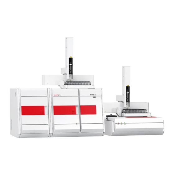
Page 45: Fig. 41 Vertical Operating Mode With Autox 112
multi X 2500 Installation and commissioning Fig. 41 Vertical operating mode with autoX 112 Fig. 42 Horizontal operating mode with ABD and autoX 112... -
Page 46: Setting Up And Connecting The Analyzer
Installation and commissioning multi X 2500 Setting up and connecting the analyzer CAUTION The multi X 2500 must only be set up, assembled and installed by the customer service department of Analytik Jena or trained specialist personnel authorized by Analytik Jena! Any unauthorized intervention on the multi X 2500 can endanger the user and the operational safety of the equipment and limits or completely invalidates any warranty... - Page 47 multi X 2500 Installation and commissioning 1. Connect the mains cables to the mains connections of the multi X 2500 and the chlorine module. Plug in the mains cable to the mains power outlet. 2. Connect the multi X 2500 and the chlorine module using the serial cable.
-
Page 48: Connecting Additional System Components
Installation and commissioning multi X 2500 Connecting additional system components The proper connection of additional system components to the multi X 2500 basic device is described in the user manual of the respective system component: Sample feeder autoX 112: ... -
Page 49: Operation
multi X 2500 Operation Operation Switching on the analyzer Before switching on check the following: The gases (oxygen, argon) are connected with a primary pressure of 4 to 6 bar. A combustion tube has been inserted in the furnace. ... -
Page 50: Switching Off The Analyzer
Operation multi X 2500 Switching off the analyzer WARNING Concentrated sulfuric acid can cause severe chemical burns! Wear protective clothing when working at the sulfuric acid container. Observe all specifications in the safety data sheet! 1. Exit the multiWin control and analysis software. Allow the device to cool down. Standard version NOTICE! Wait for a moment before switching off the basic device and the chlorine module. -
Page 51: Restarting The Analyzer After An Emergency Shutdown
multi X 2500 Operation Restarting the analyzer after an emergency shutdown WARNING Concentrated sulfuric acid can cause severe chemical burns! Wear protective clothing when working at the sulfuric acid container and the gas transfer line! Observe all specifications in the safety data sheet! If the multi X 2500 is operated with an optional multi-purpose combustion tube, there may be residual sulfuric acid in the gas transfer line after an emergency shutdown. -
Page 52: Aox Determination
AOX determination multi X 2500 AOX determination The samples for an AOX determination are prepared in accordance with column or batch method stipulated in the respective standard. The loaded activated carbon is combusted in the oxygen stream. During this process, the organically bound halogens are transformed into hydrogen halides whose mass concentration is determined as chloride. - Page 53 multi X 2500 AOX determination 2. Add 25 ml of HNO (conc.). 3. Top up with water to 1000 ml. Preparing the sample: 1. Make sure that the water sample has room temperature before initiating the adsorption. 2. Add 5 ml of nitrate stock solution to 100 ml of the sample. 3.
-
Page 54: Sample Preparation For Aox Determination From Sludge And Sediments
AOX determination multi X 2500 As an alternative to the membrane filtration, the separation of water/activated carbon AFU 3 or water/activated carbon/sludge can be effected using the automatic filtration unit AFU 3. For this process, the activated carbon or the mixture of activated carbon and sludge is pressed into a frit container (18 x 8 mm) using overpressure of up to 2 bar. -
Page 55: Preparing The Analyzer (Standard Version)
multi X 2500 AOX determination 6.2.1 Preparing the analyzer (standard version) The preparation of the analyzer includes the following steps: Insert the open combustion tube Insert the sulfuric acid container (vertically) Prepare the chlorine module The preparation of the electrolyte solution and the end point routine for the measuring cell are described in the subsequent chapter (→... - Page 56 AOX determination multi X 2500 6. Insert the combustion tube into the combustion furnace. When doing this, make sure that the connections on the combustion tube fit into the recesses on the furnace. 7. Attach the oxygen sluice (1) to the top of the combustion tube.
- Page 57 multi X 2500 AOX determination 1. Attach the drip pan (1) to the combustion furnace. 2. Fill the sulfuric acid container (vertical, 2) with 40 ml of concentrated sulfuric acid. 3. Insert the plug to the sulfuric acid container. 4. Carefully place the sulfuric acid container in the drip pan of the combustion furnace.
- Page 58 AOX determination multi X 2500 Preparing the chlorine module: 1. Fill the adsorption tube (1) with activated carbon and insert it into the chlorine module (→ "Replace the activated carbon in the adsorption tube", p. 92). 2. Insert the measuring cell "sensitive" with lid (2) into the chlorine module.
-
Page 59: Preparing The Measuring Cell
multi X 2500 AOX determination 6.2.2 Preparing the measuring cell The preparation of the measuring cell includes the following steps: Preparation of the electrolyte solution Execution of the end point routine The standard version of the analyzer is equipped with the measuring cell "sensitive". It has the same function as the optional measuring cell "high concentration"... -
Page 60: Performing Measures Using Manual Sample Feed
AOX determination multi X 2500 Pipette 8 ml of solution B into a 100-ml measuring cylinder and top up to 100 ml with solution A, or Pipette 40 ml of solution B into a 100-ml measuring cylinder and top up to 500 ml with solution A. - Page 61 multi X 2500 AOX determination 1. Fill the sulfuric acid container (vertical) with fresh sulfuric acid every day. If necessary, remove any used quartz containers from the open combustion tube and clean it. 2. Preparing the measuring cell: Fill the measuring cell with fresh electrolyte solution every day. ...
-
Page 62: Carrying Out Measurements With The Autosampler Autox 36 / Autox 36D
AOX determination multi X 2500 Create an analysis sequence. Enter the sample ID for all samples in the field N Confirm the entry with [OK]. Click the [S ] button. TART MEASUREMENT The prepared analysis sequence is processed. 14. - Page 63 multi X 2500 AOX determination Connect the gas transfer hose from the sulfuric acid container in the basic device to the combined electrode. Connect the hose for the adsorption tube (hose no. 5) via the olive-tip suction adapter to the measuring cell "sensitive". 6.
-
Page 64: Installing The Pre-Combustion Adapter
AOX determination multi X 2500 6.2.5 Installing the pre-combustion adapter CAUTION Risk of burns! Only install the combustion tube in the cold state! NOTICE Alkaline salts (hand perspiration) cause crystallizations in the quartz glass when heating the combustion furnace which reduce the service life of the combustion tube. Do not touch the combustion tube with your hands. -
Page 65: Aox Determination In Horizontal Operating Mode
multi X 2500 AOX determination AOX determination in horizontal operating mode Sample preparation Column and batch method Operating mode: horizontal Measuring cell "sensitive" Measuring range 1 to 100 µg Cl Electrolyte volume 15 to 20 ml Combustion tube Multi-purpose combustion tube manual sample With manual boat feeder (MBD) introduction... - Page 66 AOX determination multi X 2500 1. Exit the multiWin software. Allow the multi X 2500 to cool down. Then, use the mains switch to switch off the basic device and the chlorine module and cut the gas supply. 2. Tilt the combustion furnace into horizontal position. 3.
- Page 67 multi X 2500 AOX determination Inserting the multi-purpose combustion tube: WARNING Danger of explosion! The hose connections for argon and oxygen on the combustion tube must not be mixed up. CAUTION Risk of burns! Only install the combustion tube in the cold state! NOTICE Alkaline salts (hand perspiration) cause crystallizations in the quartz glass when heating the combustion furnace which reduce the service life of the combustion tube.
-
Page 68: Fig. 43 Connection Transfer Line - Sulfuric Acid Container With Outlet
AOX determination multi X 2500 5. Switch on the multi X 2500. Open the gas supply. 6. Close the pneumatic seal to the auto-protection assembly. To do this, move the toggle switch (1) down. This completes the installation of the combustion tube and the locking of the auto-protection assembly. - Page 69 multi X 2500 AOX determination 1. Carefully insert the sulfuric acid container with outlet into the bracket. 2. Close the drain cock. 3. Insert the thin hose (4) into the sulfuric acid container. Make sure that the conical nipple tightly seals the sulfuric acid container.
- Page 70 AOX determination multi X 2500 7. Attach a funnel to the sulfuric acid container. Fill 15 ml of concentrated sulfuric acid into the sulfuric acid container. 8. Remove the funnel. 9. Fit the safety attachment (7) to the sulfuric acid container and attach the safety clip.
-
Page 71: Preparing The Measuring Cell
multi X 2500 AOX determination 2. Insert the storage container for the combined electrode into the bracket in the door of the chlorine module. 3. Insert the combined electrode into the opening of the measuring cell. 4. Insert the measuring gas hose from the sulfuric acid container using the Teflon connector (1) into the connection of the combined electrode. -
Page 72: Performing Measurements
AOX determination multi X 2500 6.3.3 Performing measurements WARNING Concentrated sulfuric acid can cause severe chemical burns! Wear appropriate protective clothing when working at the sulfuric acid container. Observe all specifications in the safety data sheet! 1. Fill fresh sulfuric acid into the sulfuric acid container with outlet on the chlorine module every day (→... - Page 73 multi X 2500 AOX determination Alternatively, keep the samples at hand for introducing them with via ABD or MBD. 11. Create a new method under M and release it. M ETHOD ETHOD NEW 12. Activate the new method or an already existing method using the menu command ...
-
Page 74: Eox Determination
EOX determination multi X 2500 EOX determination Sample preparation Extraction of organically bound halogens using organic solvents Operating mode: vertical and horizontal measuring cells "sensitive" "high sensitive" Measuring range 1 to 100 µg Cl 0.01 to 10 µg Cl Electrolyte volume 15 to 20 ml 65 ml Combustion tube... -
Page 75: Preparing The Analyzer (Optional Variant)
multi X 2500 EOX determination 7.1.1 Preparing the analyzer (optional variant) The preparation of the analyzer includes the following steps: Installing the auto-protection assembly and the gas transfer line Inserting the multi-purpose combustion tube Prepare the chlorine module Refer to chapter "AOX determination in horizontal operating mode", p. - Page 76 EOX determination multi X 2500 Horizontal operating mode Vertical operating mode 4. Open the gas supply. 5. Connect hose no. 3 (1) and hose no. 4 (2) to the combustion tube. To do this, insert the hose ends into the angled adapters on the combustion tube. NOTICE! Do not push the hoses and the connectors beyond the branch length of the angled adapter.
- Page 77 multi X 2500 EOX determination It is recommended to use the measuring cell "high sensitive" for analyzing samples with low EOX content. The installation of this measuring cell is described in the following section. The use of the measuring cell "sensitive" is described under AOX determination in horizontal operating mode.
-
Page 78: Preparing The Measuring Cell
EOX determination multi X 2500 10. Connect the measuring gas hose from the sulfuric acid container to the gas inlet tube (4) using the Teflon screw connection. NOTICE! The two conical nipples of the Teflon screw connection must fit tightly to the hose. Otherwise, the gas- tightness of the connection cannot be guaranteed. - Page 79 multi X 2500 EOX determination NOTICE! Do not exceed the specified amounts of water and glacial acetic acid. Do not fill the flask up to the 1-liter mark (volume contraction). Proceed as follows to prepare 100 ml of internal electrolyte (storage solution) for the Preparing internal sensor: electrolyte...
-
Page 80: Performing Measurements
EOX determination multi X 2500 7.1.3 Performing measurements WARNING Concentrated sulfuric acid and concentrated acetic acid can cause severe chemical burns! Wear the appropriate protective clothing when pouring the electrolyte solution! Observe all instructions and specifications in the safety data sheets! 1. - Page 81 multi X 2500 EOX determination Alternatively, keep the samples at hand for introducing them manually with a syringe or an auto-injector. 11. Create a new method under M and release it. M ETHOD ETHOD NEW 12. Activate the new method or an already existing method using the menu command ...
-
Page 82: Tx/Tox Determination
TX/TOX determination multi X 2500 TX/TOX determination Sample preparation none Operating mode: horizontal vertical (for liquid, highly vaporizable samples which can be metered with a syringe) Measuring cell "sensitive" "high sensitive" "high concentration" Measuring range 1 to 100 µg Cl 0.01 to 10 µg Cl 10 to 1000 µg Cl Electrolyte volume... -
Page 83: Pox Determination
multi X 2500 POX determination POX determination Sample preparation Purging organically bound halogens in the argon stream, argon supply via gas outlet "ABD OUT" on the basic device Operating mode: vertical Measuring cell "sensitive" Measuring range 1 to 100 µg Cl Electrolyte volume 15 to 20 ml Combustion tube... - Page 84 POX determination multi X 2500 WARNING Organically bound halogens must only be purged with argon! Otherwise, there is a risk of explosion! The purging equipment must only be connected to the "ABD OUT" terminal on the rear panel of the basic device! Before starting the measurement, verify that the purging equipment is connected to the right terminal! WARNING Concentrated sulfuric acid can cause severe chemical burns! Wear appropriate...
- Page 85 multi X 2500 POX determination In the window D any components not yet ready for operation will be EVICE STATUS shown in red. The time it takes to preheat the furnace to 950 °C is about 30 to 40 min. During the warm-up phase it is not possible to start a measurement. If the analyzer is still not ready for measurements after about 40 min., carry out a fault analysis in accordance with the notes in chapter "Fault removal"...
- Page 86 POX determination multi X 2500 Fig. 46 Connection of the argon hose to the basic device and the POX container 13. Create a new method under M and release it. M ETHOD ETHOD NEW 14. Defining the analysis parameters: sample volume, furnace temperature, POX purging time, dosing time, delay time, integration time.
-
Page 87: Maintenance And Care
multi X 2500 Maintenance and care Maintenance and care 10.1 Maintenance intervals Maintenance item Action Maintenance interval Analyzer Check gas flow Daily Check system tightness Daily Clean and maintain the device Weekly Check all screw connections for tight fit Weekly Replace faulty hoses and connections If required (leakage) Check fastening screws for tight fit... -
Page 88: Replace Particle Filters In The Gas Inlets
Maintenance and care multi X 2500 Maintenance item Action Maintenance interval Sensor electrode (if using the measuring cell "high sensitive") Check filling level of internal electrolyte, Weekly top up if required Replace internal electrolyte As required Auto-protection (if using the multi-purpose combustion tube) assembly Check filters, replace if required Every three months, replace if required:... -
Page 89: Maintenance Activities (Standard Version)
multi X 2500 Maintenance and care 6. Unscrew the particle filters on the inside using a 5-mm Allen key. 7. Insert and tighten the new particle filter. 8. Screw in the gas connections and tighten them with an open-ended wrench. 9. - Page 90 Maintenance and care multi X 2500 CAUTION When working with quartz wool avoid the creation of dust! Inhaled dust might cause irritation to respiratory tracts. NOTICE Alkaline salts (hand perspiration) cause crystallizations in the quartz glass when heating the combustion furnace which reduce the service life of the combustion tube. Do not touch the combustion tube with your bare hands during re-installation.
-
Page 91: Change The Sulfuric Acid And Clean The Sulfuric Acid Container (Vertical)
multi X 2500 Maintenance and care 13. Carefully push the previously removed quartz wool plug or a new plug into the combustion tube until it reaches the bottom. The installation of the combustion tube is done in reverse order. 10.3.2 Change the sulfuric acid and clean the sulfuric acid container (vertical) WARNING Concentrated sulfuric acid can cause severe chemical burns! Wear appropriate protective clothing when working at the sulfuric acid container. -
Page 92: Replace The Activated Carbon In The Adsorption Tube
Maintenance and care multi X 2500 10.3.3 Replace the activated carbon in the adsorption tube The activated carbon must be replaced once per week or after approx. 40 operating hours. 1. Exit the multiWin control software and switch off the analyzer. -
Page 93: Clean And Store The Combined Electrode
multi X 2500 Maintenance and care Regularly check the casing of the magnetic stirring rod for cracks. Metal ions entering the electrolyte solution can distort the analysis. Avoid fluids from entering the stirring/cooling block and the plug-in contacts (risk of short circuit). -
Page 94: Checking The System For Tightness
Maintenance and care multi X 2500 10.4.2 Checking the system for tightness NOTICE Risk of destroying the internal MFM by corrosive gases! Only use the flow monitoring set included in the scope of delivery to check the system tightness. Make sure that the sulfuric acid container is completely empty. - Page 95 multi X 2500 Maintenance and care Fig. 48 Connection of the flow monitoring set 6. Read the current gas flow rate from the menu S C in the YSTEM OMPONENT TEST tab. 7. If the displayed flow rate diverges from the target flow rate by more than ±10 ml/min, find the cause and correct the defect.
-
Page 96: Servicing The Auto-Protection Assembly
Maintenance and care multi X 2500 10.4.3 Servicing the auto-protection assembly CAUTION There is a risk of burns on the combustion furnace! Only install the auto-protection assembly when the device is cold or allow the device to cool down sufficiently! NOTICE Always switch off all components of the multi X 2500 before electrically connecting them! Connecting or disconnecting electrical contacts may damage the sensitive... - Page 97 multi X 2500 Maintenance and care 10. Hold the auto-protection assembly with the left hand and pull the knob of the clamping mount with the right hand to open the lock. Remove the auto-protection assembly from the bracket on the combustion furnace. The condition of the filter in the auto-protection assembly must be checked every Check/replace filter three months.
- Page 98 Maintenance and care multi X 2500 6. Remove the worn filter and insert a new filter. The installation position of the filter does not matter. 7. Reassemble the auto-protection assembly in reverse order and reinsert it to the multi X 2500. ...
- Page 99 multi X 2500 Maintenance and care 6. Remove the pneumatic seal from the housing. 7. Pull the second PTFE disk from the bottom of the seal. 8. Carefully separate the black special seal from the ring. 9. Insert a new special seal into the ring. 10.
-
Page 100: Removing And Cleaning The Multi-Purpose Combustion Tube
Maintenance and care multi X 2500 10.4.4 Removing and cleaning the multi-purpose combustion tube WARNING Danger of explosion! The hose connections for argon and oxygen on the combustion tube must not be mixed up when reinstalling the assembly. CAUTION Risk of burns! Only remove the combustion tube when the device is cold! NOTICE Alkaline salts (hand perspiration) cause crystallizations in the quartz glass when heating the combustion furnace which reduce the service life of the combustion tube. -
Page 101: Changing The Sulfuric Acid And Cleaning The Sulfuric Acid Container With Outlet
multi X 2500 Maintenance and care 8. Pull hose no. 3 (1) and hose no. 4 (2) from the angled adapters at the combustion tube. If used, remove the flame sensor from the connection (3). 9. Carefully remove the combustion tube from the furnace. 10. - Page 102 Maintenance and care multi X 2500 Replace sulfuric acid: 1. Check if beaker (1) and Petri dish (2) have been placed under the sulfuric acid container with outlet. 2. Detach the measuring gas hose (3): When using the measuring cell "high sensitive": from the ...
- Page 103 multi X 2500 Maintenance and care 6. Attach a funnel to the sulfuric acid container. Fill 15 ml of concentrated sulfuric acid into the sulfuric acid container. 7. Remove the funnel. 8. Fit the safety attachment (2) to the sulfuric acid container and attach the safety clip.
-
Page 104: Maintaining The Measuring Cell
Maintenance and care multi X 2500 Then, allow the device to dry or dry it with an inert gas. Refer to "Preparing the chlorine module" S. 68 for information on the installation of the sulfuric acid container. 10.4.6 Maintaining the measuring cell Since the continuous introduction of hot reaction gases during operation causes electrolyte components to evaporate, it is recommended to change the electrolyte solution for the measuring cells "sensitive"... -
Page 105: Clean And Store The Electrode
multi X 2500 Maintenance and care 10.4.7 Clean and store the electrode Refer to the chapter "combined electrode" S. 93 on page for information on the maintenance of the combined electrode. Observe the following instructions when servicing the sensor electrode: Sensor electrode ... -
Page 106: Fault Removal
Fault removal multi X 2500 Fault removal For fault analysis it is possible to record log files. The recording of log files should be enabled in coordination with the Analytik Jena customer service department. Enable the recording of the device-specific log files multiWin_Comm.log and multiWin_Flow.log under E ... - Page 107 multi X 2500 Fault removal Communication error: Serial interface not available! Cause Remedy Communication problems Disconnect USB connection between basic device and PC and re-connect after approx. 10 s Initialize Communication error: Serial interface not available! Cause Remedy Communication problems ...
- Page 108 Fault removal multi X 2500 Firmware reset Cause Remedy Internal computer (firmware) restarted Acknowledge message Initialize Incomplete command from PC Command from PC without STX Command from PC: CRC error Command from PC is invalid command Command from PC: Invalid MEASURING command Command MTXT from PC is missing Cause Remedy...
- Page 109 multi X 2500 Fault removal Gasbox: no connection Cause Remedy Communication error Acknowledge message Initialize Gasbox: error while setting up nominal flow Cause Remedy Communication error Acknowledge message Initialize Gasbox: conversion error 1 Gasbox: conversion error 2 Gasbox: conversion error 3 Gasbox: conversion error 4 Cause...
- Page 110 Fault removal multi X 2500 Sampler: wrong syringe size Cause Remedy No syringe inserted Insert syringe into autoX 112 Dosing volume in the method greater than inserted Adjust dosing volume syringe The method for dosing liquids is to be enabled and the ...
-
Page 111: Equipment Faults And Analytical Problems
multi X 2500 Fault removal Auto-injector – syringe: incorrect size Cause Remedy Dosing volume and syringe size differ Adjust dosing volume and syringe size Auto-injector – syringe: not filled properly Cause Remedy Syringe not drawn all the way to the stop ... - Page 112 Fault removal multi X 2500 Furnace temperature is outside tolerance limits or target temperature is not reached Cause Solution Temperature controller faulty Report to customer service Electronics error Process gases (inlet flow) are not present Cause Solution ...
-
Page 113: Analytical Problems
multi X 2500 Fault removal 11.2.3 Analytical problems Combustion at the cannula Cause Solution Argon and oxygen connection on the multi-purpose Connect gases correctly (1-2 in Fig. 10, p. 23) combustion tube were mixed up Low results independent of detection Cause Solution ... -
Page 114: Transport And Storage
Transport and storage multi X 2500 Transport and storage Observe the safety instructions in chapter "Safety instructions, transport and commissioning", p. 10. Take particular care when transporting the basic device and the chlorine module to prevent damage from impact or vibration. Use the original packaging for transporting the basic device and its system components (e.g. -
Page 115: Prepare Device For Transport (Optional Version)
multi X 2500 Transport and storage 1. Remove the combined electrode from the measuring cell. To do this, detach the In the chlorine module hose connection and the electrical connection. Put the electrode into its original packaging. 2. Detach the electrical connection of the measuring cell. Remove the measuring cell from the chlorine module and rinse it. -
Page 116: Removing And Installing The Combustion Furnace
Transport and storage multi X 2500 2. Remove the combustion tube. 3. Detach the gas transfer line from the connections and remove it. 4. Remove the auto-protection assembly. 5. Remove the combustion furnace (→ "Removing the combustion furnace", p. 116). 6. - Page 117 multi X 2500 Transport and storage 5. Tilt the combustion furnace into vertical position to access the interfaces in the device interior. 6. Remove the grounding conductor of the combustion furnace from the floor plate connection. 7. Detach the connectors from the slots. Connector of the flame sensor (1) ...
-
Page 118: Installing The Combustion Furnace
Transport and storage multi X 2500 10. Carefully lift the combustion furnace out of tilting mechanism of the multi X 2500. 11. Reinsert the front doors. 12.3.2 Installing the combustion furnace WARNING Danger of electric shock! Before installing the combustion furnace switch off the multi X 2500 using the mains switch and disconnect the mains plug from the power outlet! 1. - Page 119 multi X 2500 Transport and storage 5. Plug in the grounding conductor of the combustion furnace in the floor plate connection. 6. Plug in the connectors to their respective slots: Connector of the flame sensor (1) Connector of the combustion furnace (2) ...
-
Page 120: Ambient Conditions For Transport And Storage
Transport and storage multi X 2500 12.4 Ambient conditions for transport and storage NOTICE Environmental influences and condensation can destroy individual components of the multi X 2500! The multi X 2500 must be stored in an air conditioned room. The atmosphere must be free from halogens and hydrocarbons, low in dust and free from aggressive vapors. -
Page 121: Disposal
multi X 2500 Disposal Disposal In a first step, carefully dilute the used desiccant with water before neutralizing it with Sulfuric acid sodium hydroxide. Observe the corresponding hazard statements and safety advice! The neutralized waste must be brought to the appropriate waste disposal center for correct disposal according to the appropriate legal guidelines. -
Page 122: Specification
Specification multi X 2500 Specification 14.1 Technical data General characteristics Designation/type Analyzer multi X 2500 Dimensions of the basic device approx. 510 x 470 x 560 mm (W x H x D) Dimensions of the chlorine module approx. 300 x 470 x 560 mm (W x H x D) Weight of the basic device approx. - Page 123 multi X 2500 Specification Measuring cell "high Measurement mode Potentiometry sensitive" Measuring range 0.01 to 10 µg Cl Generator current 100 µA Electrolyte volume 65 ml Measuring cell "sensitive" Measurement mode Bi-amperometry Measuring range 1 to 100 µg Cl Generator current 1 mA Electrolyte volume 15 to 20 ml...
-
Page 124: Guidelines And Standards
Specification multi X 2500 14.2 Guidelines and standards The analyzer has a protection class of I. Safety class and safety type The housing has safety type IP 20. The analyzer complies with the safety standards Device safety EN 61010-1 ...
Need help?
Do you have a question about the Analytik Jena Multi X 2500 and is the answer not in the manual?
Questions and answers