ZyXEL Communications ES3500-24 User Manual
Layer 2 management switch
Hide thumbs
Also See for ES3500-24:
- Brochure (4 pages) ,
- User manual (360 pages) ,
- Specifications (4 pages)
Table of Contents
Advertisement
Quick Links
ES3500-24
Layer 2 Management Switch
Default Login Details
IP Address
http://192.168.1.1
User Name
Password
Version 4.00
Edition 2, 2/2012
www.zyxel.com
www.zyxel.com
admin
1234
IMPORTANT!
READ CAREFULLY
BEFORE USE.
KEEP THIS GUIDE
FOR FUTURE
REFERENCE.
Copyright © 2012
ZyXEL Communications Corporation
Advertisement
Table of Contents
Troubleshooting

Related Manuals for ZyXEL Communications ES3500-24


Summary of Contents for ZyXEL Communications ES3500-24
- Page 1 ES3500-24 Layer 2 Management Switch Default Login Details IMPORTANT! IP Address http://192.168.1.1 READ CAREFULLY User Name admin BEFORE USE. Password 1234 KEEP THIS GUIDE FOR FUTURE REFERENCE. Version 4.00 Edition 2, 2/2012 www.zyxel.com www.zyxel.com Copyright © 2012 ZyXEL Communications Corporation...
-
Page 2: Related Documentation
Note: It is recommended you use the Web Configurator to configure the Switch. • Web Configurator Online Help Click the help icon in any screen for help in configuring that screen and supplementary information. • Support Disc Refer to the included CD for support documents. ES3500-24 User’s Guide... -
Page 3: Table Of Contents
VLAN Stacking .........................173 Multicast ...........................180 AAA ............................195 IP Source Guard ........................208 Loop Guard ..........................227 VLAN Mapping .........................231 Layer 2 Protocol Tunneling ......................235 sFlow ............................239 PPPoE ............................243 Error Disable ..........................251 Private VLAN ..........................256 Static Route ..........................259 Differentiated Services ......................262 ES3500-24 User’s Guide... - Page 4 Contents Overview DHCP ............................270 Maintenance ..........................277 Access Control .........................284 Diagnostic ..........................306 Syslog ............................307 Cluster Management ........................310 MAC Table ..........................316 ARP Table ..........................319 Configure Clone ........................321 Troubleshooting ........................325 ES3500-24 User’s Guide...
-
Page 5: Table Of Contents
Hardware Overview ........................ 26 3.1 Front Panel ..........................26 3.1.1 Console Port .......................27 3.1.2 Ethernet Ports ......................27 3.1.3 Transceiver Slots ......................28 3.1.4 Power Connector ......................30 3.2 LEDs ...........................30 Chapter 4 The Web Configurator ......................33 4.1 Introduction ..........................33 ES3500-24 User’s Guide... - Page 6 6.5.3 Enabling Guest VLAN ....................66 6.6 How to Do Port Isolation in a VLAN ..................67 6.6.1 Creating a VLAN ......................68 6.6.2 Creating a Private VLAN Rule ..................70 Part II: Technical Reference..............73 Chapter 7 System Status and Port Statistics..................75 ES3500-24 User’s Guide...
- Page 7 9.9 Configuring Protocol Based VLAN ...................102 9.10 Create an IP-based VLAN Example .................103 9.11 Port-based VLAN Setup ....................104 9.11.1 Configure a Port-based VLAN ................105 Chapter 10 Static MAC Forward Setup....................108 10.1 Overview ..........................108 10.2 Configuring Static MAC Forwarding ................108 ES3500-24 User’s Guide...
- Page 8 14.1.1 CIR and PIR ......................135 14.2 Bandwidth Control Setup ....................136 Chapter 15 Broadcast Storm Control ..................... 138 15.1 Broadcast Storm Control Setup ..................138 Chapter 16 Mirroring ..........................140 16.1 Port Mirroring Setup ......................140 Chapter 17 Link Aggregation ........................142 ES3500-24 User’s Guide...
- Page 9 21.1.2 DSCP and Per-Hop Behavior .................165 21.2 Configuring Policy Rules ....................165 21.3 Viewing and Editing Policy Configuration .................168 21.4 Policy Example .........................169 Chapter 22 Queuing Method ........................170 22.1 Queuing Method Overview ....................170 22.1.1 Strictly Priority Queuing ..................170 ES3500-24 User’s Guide...
- Page 10 AAA ............................195 25.1 Authentication, Authorization and Accounting (AAA) ............195 25.1.1 Local User Accounts ....................195 25.1.2 RADIUS and TACACS+ ..................196 25.2 AAA Screens ........................196 25.2.1 RADIUS Server Setup ..................196 25.2.2 TACACS+ Server Setup ..................199 25.2.3 AAA Setup ......................201 ES3500-24 User’s Guide...
- Page 11 28.2 Enabling VLAN Mapping ....................232 28.3 Configuring VLAN Mapping ....................233 Chapter 29 Layer 2 Protocol Tunneling....................235 29.1 Layer 2 Protocol Tunneling Overview ................235 29.1.1 Layer-2 Protocol Tunneling Mode ................236 29.2 Configuring Layer 2 Protocol Tunneling ................237 Chapter 30 sFlow............................239 ES3500-24 User’s Guide...
- Page 12 Chapter 35 Differentiated Services......................262 35.1 DiffServ Overview ......................262 35.1.1 DSCP and Per-Hop Behavior .................262 35.1.2 DiffServ Network Example ..................262 35.2 Two Rate Three Color Marker Traffic Policing ..............263 35.2.1 TRTCM-Color-blind Mode ..................264 35.2.2 TRTCM-Color-aware Mode ..................264 ES3500-24 User’s Guide...
- Page 13 Access Control ........................284 38.1 Access Control Overview .....................284 38.2 The Access Control Main Screen ..................284 38.3 About SNMP ........................284 38.3.1 SNMP v3 and Security ...................285 38.3.2 Supported MIBs .....................286 38.3.3 SNMP Traps ......................286 38.3.4 Configuring SNMP ....................290 ES3500-24 User’s Guide...
- Page 14 MAC Table ..........................316 42.1 MAC Table Overview .......................316 42.2 Viewing the MAC Table ....................317 Chapter 43 ARP Table ..........................319 43.1 ARP Table Overview .......................319 43.1.1 How ARP Works .....................319 43.2 The ARP Table Screen ....................320 ES3500-24 User’s Guide...
- Page 15 Chapter 45 Troubleshooting........................325 45.1 Power, Hardware Connections, and LEDs ...............325 45.2 Switch Access and Login ....................326 45.3 Switch Configuration ......................328 Appendix A Common Services .................... 329 Appendix B Legal Information....................333 Safety Warnings........................336 Index ............................339 ES3500-24 User’s Guide...
- Page 16 Table of Contents ES3500-24 User’s Guide...
-
Page 17: User's Guide
User’s Guide... -
Page 19: Getting To Know Your Switch
Switch’s port or connect other switches to the Switch. In this example, all computers can share high-speed applications on the server. To expand the network, simply add more networking devices such as switches, routers, computers, print servers etc. Figure 1 Backbone Application ES3500-24 User’s Guide... -
Page 20: Bridging Example
ATM at much lower cost while still being able to use existing adapters and switches. Moreover, the current LAN structure can be retained as all ports can freely communicate with each other. Figure 3 High Performance Switched Workgroup Application ES3500-24 User’s Guide... -
Page 21: Ieee 802.1Q Vlan Application Examples
• IPv4/IPv6 dual stack; the Switch can run IPv4 and IPv6 at the same time • DHCPv6 client and relay • Multicast Listener Discovery (MLD) snooping and proxy For more information on IPv6, refer to the CLI Reference Guide. ES3500-24 User’s Guide... -
Page 22: Ways To Manage The Switch
Switch to its factory default settings. If you backed up an earlier configuration file, you would not have to totally re-configure the Switch. You could simply restore your last configuration. ES3500-24 User’s Guide... -
Page 23: Hardware Installation And Connection
2.3.1 Rack-mounted Installation Requirements • Two mounting brackets. • Eight M3 flat head screws and a #2 Philips screwdriver. • Four M5 flat head screws and a #2 Philips screwdriver. Failure to use the proper screws may damage the unit. ES3500-24 User’s Guide... -
Page 24: Attaching The Mounting Brackets To The Switch
Using a #2 Philips screwdriver, install the M3 flat head screws through the mounting bracket holes into the Switch. Repeat steps to install the second mounting bracket on the other side of the Switch. You may now mount the Switch on a rack. Proceed to the next section. ES3500-24 User’s Guide... -
Page 25: Mounting The Switch On A Rack
Figure 6 Mounting the Switch on a Rack Using a #2 Philips screwdriver, install the M5 flat head screws through the mounting bracket holes into the rack. Repeat steps to attach the second mounting bracket on the other side of the rack. ES3500-24 User’s Guide... -
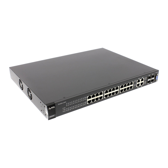
Page 26: Hardware Overview
Four 100/1000 Mbps RJ-45 Ports: Connect these ports to high-bandwidth backbone network Ethernet switches using 1000BASE-T compatible Category 5/5e/6 copper cables. • Four Mini GBIC Slots: Use mini GBIC transceivers in these slots for connections to backbone Ethernet switches. ES3500-24 User’s Guide... -
Page 27: Console Port
Ethernet port are the same in order to connect. 3.1.2.1 Default Ethernet Negotiation Settings The factory default negotiation settings for the Gigabit ports on the Switch are: • Speed: Auto ES3500-24 User’s Guide... -
Page 28: Transceiver Slots
Insert the transceiver into the slot with the exposed section of PCB board facing down. Press the transceiver firmly until it clicks into place. The Switch automatically detects the installed transceiver. Check the LEDs to verify that it is functioning properly. Close the transceiver’s latch (latch styles vary). ES3500-24 User’s Guide... -
Page 29: Transceiver Removal
Remove the fiber optic cables from the transceiver. Open the transceiver’s latch (latch styles vary). Pull the transceiver out of the slot. Figure 11 Removing the Fiber Optic Cables Figure 12 Opening the Transceiver’s Latch Example Figure 13 Transceiver Removal Example ES3500-24 User’s Guide... -
Page 30: Power Connector
The link to an Ethernet network is down. Mini-GBIC Slots Green The link to this port is up. The link to this port is down. Green Blinking This port is receiving or transmitting data. 1000Base-T Ethernet Ports (in Dual Personality Interface) ES3500-24 User’s Guide... - Page 31 The link to a 10 Mbps or a 100 Mbps Ethernet network is up. The link to an Ethernet network is down. Amber The Gigabit port is negotiating in full-duplex mode. The Gigabit port is negotiating in half-duplex mode. ES3500-24 User’s Guide...
- Page 32 Chapter 3 Hardware Overview ES3500-24 User’s Guide...
-
Page 33: The Web Configurator
• Java permissions (enabled by default). 4.2 System Login Start your web browser. Type “http://” and the IP address of the Switch (for example, the default management IP address is 192.168.1.1) in the Location or Address field. Press [ENTER]. ES3500-24 User’s Guide... -
Page 34: The Web Configurator Layout
General Setup screen. Figure 14 Web Configurator: Login Click OK to view the first web configurator screen. 4.3 The Web Configurator Layout The Status screen is the first screen that displays when you access the web configurator. ES3500-24 User’s Guide... - Page 35 C - Click this link to go to the status page of the Switch. D - Click this link to log out of the web configurator. E - Click this link to display web help pages. The help pages provide descriptions for all of the configuration screens. ES3500-24 User’s Guide...
- Page 36 This link takes you to screens where you can configure port-based or 802.1Q VLAN (depending on what you configured in the Switch Setup menu). You can also configure a protocol based VLAN or a subnet based VLAN in these screens. ES3500-24 User’s Guide...
- Page 37 This link takes you to screens where you can configure how the Switch gives a PPPoE termination server additional subscriber information that the server can use to identify and authenticate a PPPoE client. Errdisable This link takes you to a screen where you can configure CPU protection and error disable recovery. ES3500-24 User’s Guide...
- Page 38 This link takes you to a screen where you can view the MAC address – IP address resolution table. Configure Clone This link takes you to a screen where you can copy attributes of one port to (an)other port(s). ES3500-24 User’s Guide...
-
Page 39: Change Your Password
Delete the management VLAN (default is VLAN 1). Delete all port-based VLANs with the CPU port as a member. The “CPU port” is the management port of the Switch. Filter all traffic to the CPU port. ES3500-24 User’s Guide... -
Page 40: Resetting The Switch
When you see the message “Press any key to enter Debug Mode within 3 seconds ...” press any key to enter debug mode. Type atlc after the “Enter Debug Mode” message. Wait for the “Starting XMODEM upload” message before activating XMODEM upload on your terminal. ES3500-24 User’s Guide... -
Page 41: Logging Out Of The Web Configurator
Figure 18 Web Configurator: Logout Screen 4.8 Help The web configurator’s online help has descriptions of individual screens and some supplementary information. Click the Help link from a web configurator screen to view an online help description of that screen. ES3500-24 User’s Guide... - Page 42 Chapter 4 The Web Configurator ES3500-24 User’s Guide...
-
Page 43: Initial Setup Example
VLANs confine broadcast frames to the VLAN group in which the port(s) belongs. You can do this with port-based VLAN or tagged static VLAN with fixed port members. In this example, you want to configure port 1 as a member of VLAN 2. Figure 19 Initial Setup Network Example: VLAN ES3500-24 User’s Guide... -
Page 44: Setting Port Vid
Switch’s power is turned off. 5.1.2 Setting Port VID Use PVID to add a tag to incoming untagged frames received on that port so that the frames are forwarded to the VLAN group that the tag defines. ES3500-24 User’s Guide... -
Page 45: Configuring Switch Management Ip Address
The default management IP address of the Switch is 192.168.1.1. You can configure another IP address in a different subnet for management purposes. The following figure shows an example. Figure 21 Initial Setup Example: Management IP Address ES3500-24 User’s Guide... - Page 46 VLAN ID you configure in the Static VLAN screen. Click Add to save your changes back to the run-time memory. Settings in the run-time memory are lost when the Switch’s power is turned off. ES3500-24 User’s Guide...
-
Page 47: Tutorials
DHCP Server (A) 1 and 100 DHCP Client (B) 1 and 100 DHCP Client (C) 1 and 100 Access the Switch through http://192.168.1.1. Log into the Switch by entering the username (default: admin) and password (default: 1234). ES3500-24 User’s Guide... - Page 48 Go to Advanced Application > VLAN > VLAN Port Setting, and set the PVID of the ports 5, 6 and 7 to 100. This tags untagged incoming frames on ports 5, 6 and 7 with the tag 100. ES3500-24 User’s Guide...
- Page 49 The DHCP Snooping Port Configure screen appears. Select Trusted in the Server Trusted state field for port 5 because the DHCP server is connected to port 5. Keep ports 6 and 7 Untrusted because they are connected to DHCP clients. Click Apply. ES3500-24 User’s Guide...
-
Page 50: How To Use Dhcp Relay On The Switch
6.2 How to Use DHCP Relay on the Switch This tutorial describes how to configure your Switch to forward DHCP client requests to a specific DHCP server. The DHCP server can then assign a specific IP address based on the information in the DHCP requests. ES3500-24 User’s Guide... -
Page 51: Dhcp Relay Tutorial Introduction
Access the web configurator through the Switch’s port which is not in VLAN 102. Go to Basic Setting > Switch Setup and set the VLAN type to 802.1Q. Click Apply to save the settings to the run-time memory. ES3500-24 User’s Guide... - Page 52 Click Add to save the settings to the run-time memory. Settings in the run-time memory are lost when the Switch’s power is turned off. Click the VLAN Status link in the Static VLAN screen and then the VLAN Port Setting link in the VLAN Status screen. ES3500-24 User’s Guide...
-
Page 53: Configuring Dhcp Relay
Click IP Application > DHCP and then the Global link to open the DHCP Relay screen. Select the Active check box. Enter the DHCP server’s IP address (192.168.2.3 in this example) in the Remote DHCP Server 1 field. Select the Option 82 and the Information check boxes. ES3500-24 User’s Guide... -
Page 54: Troubleshooting
6.3 How to Use PPPoE IA on the Switch You want to configure PPPoE Intermediate Agent on the Switch (A) to pass a subscriber’s information to a PPPoE server (S). There is another switch (B) between switch A and server S. ES3500-24 User’s Guide... -
Page 55: Configuring Switch A
Port 12 (to B) Trusted Port 11 (to A) Trusted Port 12 (to S) Trusted 6.3.1 Configuring Switch A Click Advanced Application > PPPoE > Intermediate Agent. Select Active then click Apply. Click Port on the top of the screen. ES3500-24 User’s Guide... - Page 56 Select Trusted for port 12 and then leave the other fields empty. Click Apply. Then Click Intermediate Agent on the top of the screen. The Intermediate Agent screen appears. Click VLAN on the top of the screen. ES3500-24 User’s Guide...
-
Page 57: Configuring Switch B
Then select Yes to enable PPPoE IA in VLAN 1 and also select Circuit-id and Remote-id to allow the Switch to add these two strings to frames tagged with VLAN 1 and pass to the PPPoE server. Click Apply. 6.3.2 Configuring Switch B The example uses another ES3500-24 as switch B. ES3500-24 User’s Guide... - Page 58 Click Advanced Application > PPPoE > Intermediate Agent. Select Active then click Apply. Click Port on the top of the screen. Select Trusted for ports 11 and 12 and then click Apply. Then Click Intermediate Agent on the top of the screen. ES3500-24 User’s Guide...
- Page 59 Then select Yes to enable PPPoE IA in VLAN 1 and also select Circuit-id and Remote-id to allow the Switch to add these two strings to frames tagged with VLAN 1 and pass to the PPPoE server. Click Apply. ES3500-24 User’s Guide...
-
Page 60: How To Use Error Disable And Recovery On The Switch
First, click Advanced Application > Loop Guard. Select the Active option in the first section to enable loop guard on the Switch. Then select the Active option of the first entry (port *) to enable loop guard for all ports. Click Apply. ES3500-24 User’s Guide... - Page 61 Then click Apply. Click Advanced Application > Errdisable > Errdisable Recovery, select Active and Timer Status for loopguard and ARP entries. Also enter 180 (180 seconds = 3 minutes) in the Interval field for both entries. Then click Apply. ES3500-24 User’s Guide...
-
Page 62: How To Set Up A Guest Vlan
6.5.1 Creating a Guest VLAN Follow the steps below to configure port 1, 2, 3 and 10 as a member of VLAN 200. Access the web configurator through the Switch’s port which is not in VLAN 200. ES3500-24 User’s Guide... - Page 63 Select Fixed to configure ports 1, 2, 3 and 10 to be permanent members of this VLAN. Clear the TX Tagging check box to set the Switch to remove VLAN tags before sending frames out of these ports. ES3500-24 User’s Guide...
- Page 64 Enter 200 in the PVID field for ports 1, 2, 3 and 10 to add a tag to incoming untagged frames received on these ports so that the frames are forwarded to the VLAN group that the tag defines. ES3500-24 User’s Guide...
-
Page 65: Enabling Ieee 802.1X Port Authentication
6.5.2 Enabling IEEE 802.1x Port Authentication Follow the steps below to enable port authentication to validate access to ports 1~8 to clients based on a RADIUS server. Click Advanced Application > Port Authentication and then the Click Here link for 802.1x. ES3500-24 User’s Guide... -
Page 66: Enabling Guest Vlan
Select the first Active checkbox to enable 802.1x authentication on the Switch. Select the Active checkboxes for ports 1 to 8 to turn on 802.1x authentication on the selected ports. Click Apply. 6.5.3 Enabling Guest VLAN Click the Guest Vlan link in the 802.1x screen. ES3500-24 User’s Guide... -
Page 67: How To Do Port Isolation In A Vlan
6.6 How to Do Port Isolation in a VLAN You want to prevent communications between ports in a VLAN but still allow them to access the Internet or network resources through the uplink port in the same VLAN. You use private VLAN to ES3500-24 User’s Guide... -
Page 68: Creating A Vlan
Click Advanced Application > VLAN > Static VLAN. In the Static VLAN screen, select ACTIVE, enter a descriptive name (VLAN 123 for example) in the Name field and enter 123 in the VLAN Group ID field. ES3500-24 User’s Guide... - Page 69 Click Add to save the settings to the run-time memory. Settings in the run-time memory are lost when the Switch’s power is turned off. Click the VLAN Status link in the Static VLAN screen and then the VLAN Port Setting link in the VLAN Status screen. ES3500-24 User’s Guide...
-
Page 70: Creating A Private Vlan Rule
11 Click the Save link in the upper right corner of the web configurator to save your configuration permanently. 6.6.2 Creating a Private VLAN Rule Follow the steps below to configure private VLAN for VLAN 123. Click Advanced Application > Private VLAN. ES3500-24 User’s Guide... - Page 71 Ports 2, 3 and 4 in this VLAN will be added to the isolated port list automatically and cannot send traffic to each other. From port 2, 3, or 4, you should be able to access the device that attachs to port 25, such as a server or default gateway. ES3500-24 User’s Guide...
- Page 72 Chapter 6 Tutorials ES3500-24 User’s Guide...
-
Page 73: Technical Reference
Technical Reference... -
Page 75: System Status And Port Statistics
The home screen of the web configurator displays a port statistical summary with links to each port showing statistical details. 7.2 Port Status Summary To view the port statistics, click Status in all web configurator screens to display the Status screen as shown next. Figure 22 Status ES3500-24 User’s Guide... - Page 76 This field shows the total amount of time in hours, minutes and seconds the port has been up. Clear Counter Enter a port number and then click Clear Counter to erase the recorded statistical information for that port, or select Any to clear statistics for all ports. ES3500-24 User’s Guide...
-
Page 77: Status: Port Details
If STP (Spanning Tree Protocol) is enabled, this field displays the STP state of the port (see Section 13.1 on page 116 for more information). If STP is disabled, this field displays FORWARDING if the link is up, otherwise, it displays STOP. ES3500-24 User’s Guide... - Page 78 This field shows the number of packets (including bad packets) received that were between 128 and 255 octets in length. 256-511 This field shows the number of packets (including bad packets) received that were between 256 and 511 octets in length. ES3500-24 User’s Guide...
- Page 79 1024 and 1518 octets in length. Giant This field shows the number of packets (including bad packets) received that were between 1519 octets and the maximum frame size. The maximum frame size varies depending on your switch model. ES3500-24 User’s Guide...
-
Page 80: Basic Setting
In the navigation panel, click Basic Setting > System Info to display the screen as shown. You can check the firmware version number and monitor the Switch temperature and voltage in this screen. Figure 24 Basic Setting > System Info ES3500-24 User’s Guide... - Page 81 This field displays the minimum voltage measured at this point. Threshold This field displays the percentage tolerance of the voltage with which the Switch still works. Status Normal indicates that the voltage is within an acceptable operating range at this point; otherwise Error is displayed. ES3500-24 User’s Guide...
-
Page 82: General Setup
Address 60 seconds. If you select a timeserver that is unreachable, then this screen will appear locked for 60 seconds. Please wait. Current Time This field displays the time you open this menu (or refresh the menu). ES3500-24 User’s Guide... -
Page 83: Introduction To Vlans
When properly configured, VLAN prevents one subscriber from accessing the network resources of another on the same LAN, thus a user will not see the printers and hard disks of another user in the same building. ES3500-24 User’s Guide... -
Page 84: Smart Isolation
C. Traffic received on designated port 8 from switch C will not be forwarded to any other isolated ports on switch B. Before Smart Isolation: Isolated ports: 2~6 Root port: 7 Designated port: 8 After Smart Isolation: Isolated ports: 2~6, 8 Root port: 7 Designated port: 8 ES3500-24 User’s Guide... -
Page 85: Switch Setup
VLAN and (M)RSTP on the Switch. Smart isolation does not work with MSTP and/or port-based VLAN. MAC Address MAC address learning reduces outgoing traffic broadcasts. For MAC address Learning learning to occur on a port, the port must be active. ES3500-24 User’s Guide... - Page 86 Save link on the top navigation panel to save your changes to the non-volatile memory when you are done configuring. Cancel Click Cancel to reset the fields. ES3500-24 User’s Guide...
-
Page 87: Ip Setup
You can configure up to 64 IP addresses which are used to access and manage the Switch from the ports belonging to the pre-defined VLAN(s). Note: You must configure a VLAN first. Figure 27 Basic Setting > IP Setup ES3500-24 User’s Guide... - Page 88 This field displays the IP address. IP Subnet Mask This field displays the subnet mask. This field displays the ID number of the VLAN group. Default Gateway This field displays the IP address of the default gateway. ES3500-24 User’s Guide...
-
Page 89: Port Setup
Enter a descriptive name that identifies this port. You can enter up to 64 alpha-numerical characters. Note: Due to space limitation, the port name may be truncated in some web configurator screens. Type This field displays 10/100M for Fast Ethernet connections and 10/100/1000M for Gigabit connections. ES3500-24 User’s Guide... - Page 90 Save link on the top navigation panel to save your changes to the non-volatile memory when you are done configuring. Cancel Click Cancel to begin configuring this screen afresh. ES3500-24 User’s Guide...
-
Page 91: Vlan
A broadcast frame (or a multicast frame for a multicast group that is known by the system) is duplicated only on ports that are members of the VID (except the ingress port itself), thus confining the broadcast to a specific domain. ES3500-24 User’s Guide... -
Page 92: Automatic Vlan Registration
You may choose to accept both tagged and untagged incoming Type frames, just tagged incoming frames or just untagged incoming frames on a port. Ingress filtering If set, the Switch discards incoming frames for VLANs that do not have this port as a member. ES3500-24 User’s Guide... -
Page 93: Port Vlan Trunking
• sent to a group whether it has a VLAN tag or not. • blocked from a VLAN group regardless of its VLAN tag. You can also tag all outgoing frames (that were previously untagged) from a port with the specified VID. ES3500-24 User’s Guide... -
Page 94: Vlan Status
- added in another way such as via Multicast VLAN Registration (MVR). Change Pages Click Previous or Next to show the previous/next screen if all status information cannot be seen in one screen. ES3500-24 User’s Guide... -
Page 95: Vlan Details
Status This field shows how this VLAN was added to the Switch; dynamic - using GVRP, static - added as a permanent entry or other - added in another way such as via Multicast VLAN Registration (MVR). ES3500-24 User’s Guide... -
Page 96: Configure A Static Vlan
Select Normal for the port to dynamically join this VLAN group using GVRP. This is the default selection. Select Fixed for the port to be a permanent member of this VLAN group. Select Forbidden if you want to prohibit the port from joining this VLAN group. ES3500-24 User’s Guide... -
Page 97: Configure Vlan Port Settings
GVRP (GARP VLAN Registration Protocol) is a registration protocol that defines a way for switches to register necessary VLAN members on ports across the network. Select this check box to permit VLAN groups beyond the local Switch. Port This field displays the port number. ES3500-24 User’s Guide... -
Page 98: Subnet Based Vlans
IP subnet 172.16.1.0/24 (voice services). You can also have a subnet based VLAN with priority 5 and VID of 200 for traffic received from IP subnet 192.168.1.0/24 (video services). Lastly, you can configure VLAN with priority 3 and VID of 300 for traffic received from IP subnet 10.1.1.0/24 (data ES3500-24 User’s Guide... -
Page 99: Configuring Subnet Based Vlan
Internet Untagged Frames 10.1.1.0/24 172.16.1.0/24 192.168.1.0/24 VID = 300 VID = 100 VID = 200 9.7 Configuring Subnet Based VLAN Click Subnet Based VLAN in the VLAN Port Setting screen to display the configuration screen as shown. ES3500-24 User’s Guide... - Page 100 VLAN are tagged. This must be an existing VLAN which you defined in the Advanced Applications > VLAN screens. Priority Select the priority level that the Switch assigns to frames belonging to this VLAN. ES3500-24 User’s Guide...
-
Page 101: Protocol Based Vlans
1, 2 and 3. You can also have a protocol based VLAN B with priority 2 for Apple Talk traffic received on port 6 and 7. All upstream ARP traffic from port 1, 2 and 3 will be grouped together, and all ES3500-24 User’s Guide... -
Page 102: Configuring Protocol Based Vlan
Figure 37 Protocol Based VLAN Application Example 9.9 Configuring Protocol Based VLAN Click Protocol Based VLAN in the VLAN Port Setting screen to display the configuration screen as shown. Figure 38 Advanced Application > VLAN > VLAN Port Setting > Protocol Based VLAN ES3500-24 User’s Guide... -
Page 103: Create An Ip-Based Vlan Example
Activate this protocol based VLAN. Type the port number you want to include in this protocol based VLAN. Type 1. Give this protocol-based VLAN a descriptive name. Type IP-VLAN. Select the protocol. Leave the default value IP. ES3500-24 User’s Guide... -
Page 104: Port-Based Vlan Setup
Note: In screens (such as IP Setup and Filtering) that require a VID, you must enter 1 as the VID. The port-based VLAN setup screen is shown next. The CPU management port forms a VLAN with all Ethernet ports. ES3500-24 User’s Guide... -
Page 105: Configure A Port-Based Vlan
Isolated if you want to restrict users from communicating directly. Click Apply to save your settings. The following screen shows users on a port-based, all-connected VLAN configuration. Figure 40 Advanced Application > VLAN > Port Based VLAN Setup (All Connected) ES3500-24 User’s Guide... - Page 106 Chapter 9 VLAN The following screen shows users on a port-based, port-isolated VLAN configuration. Figure 41 Advanced Application > VLAN: Port Based VLAN Setup (Port Isolation) ES3500-24 User’s Guide...
- Page 107 Save link on the top navigation panel to save your changes to the non-volatile memory when you are done configuring. Cancel Click Cancel to begin configuring this screen afresh. ES3500-24 User’s Guide...
-
Page 108: Static Mac Forward Setup
Chapter 19 on page 158 for more information on port security. Click Advanced Applications > Static MAC Forwarding in the navigation panel to display the configuration screen as shown. Figure 42 Advanced Application > Static MAC Forwarding ES3500-24 User’s Guide... - Page 109 This field displays the port where the MAC address shown in the next field will be forwarded. Delete Click Delete to remove the selected entry from the summary table. Cancel Click Cancel to clear the Delete check boxes. ES3500-24 User’s Guide...
-
Page 110: Static Multicast Forward Setup
You can configure this in the Advanced Application > Multicast > Multicast Setting screen (see Section 24.3 on page 182). Figure 43 shows such unknown multicast frames flooded to all ports. With static multicast forwarding, you can forward these multicasts to port(s) ES3500-24 User’s Guide... -
Page 111: Configuring Static Multicast Forwarding
Figure 44 Static Multicast Forwarding to A Single Port Figure 45 Static Multicast Forwarding to Multiple Ports 11.2 Configuring Static Multicast Forwarding Use this screen to configure rules to forward specific multicast frames, such as streaming or control frames, to specific port(s). ES3500-24 User’s Guide... - Page 112 MAC Address This field displays the multicast MAC address that identifies a multicast group. This field displays the ID number of a VLAN group to which frames containing the specified multicast MAC address will be forwarded. ES3500-24 User’s Guide...
- Page 113 This field displays the port(s) within a identified VLAN group to which frames containing the specified multicast MAC address will be forwarded. Delete Click Delete to remove the selected entry from the summary table. Cancel Click Cancel to clear the Delete check boxes. ES3500-24 User’s Guide...
-
Page 114: Filtering
Select Discard destination to drop frames to the destination MAC address (specified in the MAC address). The Switch can still receive frames originating from the MAC address. Select Discard source and Discard destination to block traffic to/from the MAC address specified in the MAC field. ES3500-24 User’s Guide... - Page 115 This field displays the VLAN group identification number. Delete Check the rule(s) that you want to remove in the Delete column and then click the Delete button. Cancel Click Cancel to clear the selected checkbox(es) in the Delete column. ES3500-24 User’s Guide...
-
Page 116: Spanning Tree Protocol
RANGE Path Cost 4Mbps 100 to 1000 1 to 65535 Path Cost 10Mbps 50 to 600 1 to 65535 Path Cost 16Mbps 40 to 400 1 to 65535 Path Cost 100Mbps 10 to 60 1 to 65535 ES3500-24 User’s Guide... -
Page 117: How Stp Works
Note: The listening state does not exist in RSTP. Learning All BPDUs are received and processed. Information frames are submitted to the learning process but not forwarded. Forwarding All BPDUs are received and processed. All information frames are received and forwarded. ES3500-24 User’s Guide... -
Page 118: Multiple Rstp
Chapter 13 Spanning Tree Protocol 13.1.4 Multiple RSTP MRSTP (Multiple RSTP) is ZyXEL’s proprietary feature that is compatible with RSTP and STP. With MRSTP, you can have more than one spanning tree on your Switch and assign port(s) to each tree. -
Page 119: Mstp Network Example
Each MSTP-enabled device can only belong to one MST region. When BPDUs enter an MST region, external path cost (of paths outside this region) is increased by one. Internal path cost (of paths within this region) is increased by one when BPDUs traverse the region. ES3500-24 User’s Guide... -
Page 120: Mst Instance
MST instance are members of the CIST. In an MSTP-enabled network, there is only one CIST that runs between MST regions and single spanning tree devices. A network may contain multiple MST regions and other network segments running RSTP. Figure 52 MSTP and Legacy RSTP Network Example ES3500-24 User’s Guide... -
Page 121: Spanning Tree Protocol Status Screen
13.3 Spanning Tree Configuration Use the Spanning Tree Configuration screen to activate one of the STP modes on the Switch. Click Configuration in the Advanced Application > Spanning Tree Protocol. Figure 54 Advanced Application > Spanning Tree Protocol > Configuration ES3500-24 User’s Guide... -
Page 122: Configure Rapid Spanning Tree Protocol
Use this screen to configure RSTP settings, see Section 13.1 on page 116 for more information on RSTP. Click RSTP in the Advanced Application > Spanning Tree Protocol screen. Figure 55 Advanced Application > Spanning Tree Protocol > RSTP ES3500-24 User’s Guide... - Page 123 Priority decides which port should be disabled when more than one port forms a loop in a switch. Ports with a higher priority numeric value are disabled first. The allowed range is between 0 and 255 and the default value is 128. ES3500-24 User’s Guide...
-
Page 124: Rapid Spanning Tree Protocol Status
(second) configuration message. The root bridge determines Hello Time, Max Age and Forwarding Delay. Max Age (second) This is the maximum time (in seconds) a switch can wait without receiving a configuration message before attempting to reconfigure. ES3500-24 User’s Guide... -
Page 125: Configure Multiple Rapid Spanning Tree Protocol
Table 30 Advanced Application > Spanning Tree Protocol > MRSTP LABEL DESCRIPTION Status Click Status to display the MRSTP Status screen (see Figure 56 on page 124). Tree This is a read-only index number of the STP trees. ES3500-24 User’s Guide... - Page 126 The slower the media, the higher the cost - see Table 25 on page 116 for more information. Tree Select which STP tree configuration this port should participate in. ES3500-24 User’s Guide...
-
Page 127: Multiple Rapid Spanning Tree Protocol Status
Forwarding Delay This is the time (in seconds) the root switch will wait before changing states (that is, (second) listening to learning to forwarding). Note: The listening state does not exist in RSTP. ES3500-24 User’s Guide... - Page 128 Spanning Tree. Topology Changed This is the number of times the spanning tree has been reconfigured. Times Time Since Last This is the time since the spanning tree was last reconfigured. Change ES3500-24 User’s Guide...
-
Page 129: Configure Multiple Spanning Tree Protocol
13.8 Configure Multiple Spanning Tree Protocol To configure MSTP, click MSTP in the Advanced Application > Spanning Tree Protocol screen. Section 13.1.5 on page 118 for more information on MSTP. Figure 59 Advanced Application > Spanning Tree Protocol > MSTP ES3500-24 User’s Guide... - Page 130 Switch will be chosen as the root bridge within the spanning tree instance. Enter priority values between 0 and 61440 in increments of 4096 (thus valid values are 4096, 8192, 12288, 16384, 20480, 24576, 28672, 32768, 36864, 40960, 45056, 49152, 53248, 57344 and 61440). ES3500-24 User’s Guide...
- Page 131 This field display the ports configured to participate in the MST instance. Delete Check the rule(s) that you want to remove in the Delete column and then click the Delete button. Cancel Click Cancel to begin configuring this screen afresh. ES3500-24 User’s Guide...
-
Page 132: Multiple Spanning Tree Protocol Port Configuration
Save link on the top navigation panel to save your changes to the non-volatile memory when you are done configuring. Cancel Click Cancel to begin configuring this screen afresh. ES3500-24 User’s Guide... -
Page 133: Multiple Spanning Tree Protocol Status
This is the time (in seconds) the root switch will wait before changing states (that is, (second) listening to learning to forwarding). Cost to Bridge This is the path cost from the root port on this Switch to the root switch. ES3500-24 User’s Guide... - Page 134 This is the path cost from the root port in this MST instance to the regional root switch. Port ID This is the priority and number of the port on the Switch through which this Switch must communicate with the root of the MST instance. ES3500-24 User’s Guide...
-
Page 135: Bandwidth Control
PIR. When network congestion occurs, packets through the ingress port exceeding the CIR will be marked for drop. Note: The CIR should be less than the PIR. Note: The sum of CIRs cannot be greater than or equal to the uplink bandwidth. ES3500-24 User’s Guide... -
Page 136: Bandwidth Control Setup
Active Select this check box to activate egress rate limits on this port. Egress Rate Specify the maximum bandwidth allowed in kilobits per second (Kbps) for the out-going traffic flow on a port. ES3500-24 User’s Guide... - Page 137 Save link on the top navigation panel to save your changes to the non-volatile memory when you are done configuring. Cancel Click Cancel to begin configuring this screen afresh. ES3500-24 User’s Guide...
-
Page 138: Broadcast Storm Control
Table 36 Advanced Application > Broadcast Storm Control LABEL DESCRIPTION Active Select this check box to enable traffic storm control on the Switch. Clear this check box to disable this feature. Port This field displays a port number. ES3500-24 User’s Guide... - Page 139 Save link on the top navigation panel to save your changes to the non-volatile memory when you are done configuring. Cancel Click Cancel to begin configuring this screen afresh. ES3500-24 User’s Guide...
-
Page 140: Mirroring
The monitor port is the port you copy the traffic to in order to examine it in more detail without Port interfering with the traffic flow on the original port(s). Type the port number of the monitor port. Port This field displays the port number. ES3500-24 User’s Guide... - Page 141 Save link on the top navigation panel to save your changes to the non-volatile memory when you are done configuring. Cancel Click Cancel to begin configuring this screen afresh. ES3500-24 User’s Guide...
-
Page 142: Link Aggregation
• You must connect all ports point-to-point to the same Ethernet switch and configure the ports for LACP trunking. • LACP only works on full-duplex links. • All ports in the same trunk group must have the same media type, speed, duplex mode and flow control settings. ES3500-24 User’s Guide... -
Page 143: Link Aggregation Id
These are the ports that are currently transmitting data as one logical link in this trunk Ports group. Port Priority and Port Number are 0 as it is the aggregator ID for the trunk group, not the individual port. ES3500-24 User’s Guide... - Page 144 This field displays how these ports were added to the trunk group. It displays: • Static - if the ports are configured as static members of a trunk group. • LACP - if the ports are configured to join a trunk group via LACP. ES3500-24 User’s Guide...
-
Page 145: Link Aggregation Setting
This is the only screen you need to configure to enable static link aggregation. Aggregation Setting Group ID The field identifies the link aggregation group, that is, one logical link containing multiple ports. Active Select this option to activate a trunk group. ES3500-24 User’s Guide... - Page 146 Save link on the top navigation panel to save your changes to the non-volatile memory when you are done configuring. Cancel Click Cancel to begin configuring this screen afresh. ES3500-24 User’s Guide...
-
Page 147: Link Aggregation Control Protocol
Link Aggregation Control Protocol (LACP). The smaller the number, the higher the priority level. Group ID The field identifies the link aggregation group, that is, one logical link containing multiple ports. ES3500-24 User’s Guide... -
Page 148: Static Trunking Example
Make your physical connections - make sure that the ports that you want to belong to the trunk group are connected to the same destination. The following figure shows ports 2-5 on switch A connected to switch B. Figure 68 Trunking Example - Physical Connections ES3500-24 User’s Guide... - Page 149 Click Apply when you are done. Figure 69 Trunking Example - Configuration Screen EXAMPLE Your trunk group 1 (T1) configuration is now complete. ES3500-24 User’s Guide...
-
Page 150: Port Authentication
When the client At the time of writing, IEEE 802.1x is not supported by all operating systems. See your operating system documentation. If your operating system does not support 802.1x, then you may need to install 802.1x client software. ES3500-24 User’s Guide... -
Page 151: Mac Authentication
Session Granted/Denied 18.1.2 MAC Authentication MAC authentication works in a very similar way to IEEE 802.1x authentication. The main difference is that the Switch does not prompt the client for login credentials. The login credentials are based ES3500-24 User’s Guide... -
Page 152: Port Authentication Configuration
Radius Server Setup screen. To activate a port authentication method, click Advanced Application > Port Authentication in the navigation panel. Select a port authentication method in the screen that appears. Figure 72 Advanced Application > Port Authentication ES3500-24 User’s Guide... -
Page 153: Activate Ieee 802.1X Security
Switch tries again. If the client still does not respond to the second request, the Switch sends the client to the Guest VLAN. The client needs to send a new request to be authenticated by the Switch again. ES3500-24 User’s Guide... -
Page 154: Guest Vlan
VLAN, such as the Internet. The rights granted to the Guest VLAN depends on how the network administrator configures switches or routers with the guest network feature. Figure 74 Guest VLAN Example VLAN 100 VLAN 102 Internet ES3500-24 User’s Guide... - Page 155 Switch. You must also enable IEEE 802.1x authentication on the Switch and the associated ports. Enter the number that identifies the guest VLAN. Make sure this is a VLAN recognized in your network. ES3500-24 User’s Guide...
-
Page 156: Activate Mac Authentication
Click Cancel to begin configuring this screen afresh. 18.2.3 Activate MAC Authentication Use this screen to activate MAC authentication. In the Port Authentication screen click MAC Authentication to display the configuration screen as shown. Figure 76 Advanced Application > Port Authentication > MAC Authentication ES3500-24 User’s Guide... - Page 157 Save link on the top navigation panel to save your changes to the non-volatile memory when you are done configuring. Cancel Click Cancel to begin configuring this screen afresh. ES3500-24 User’s Guide...
-
Page 158: Port Security
By default, MAC address learning is still enabled even though the port security is not activated. 19.2 Port Security Setup Click Advanced Application > Port Security in the navigation panel to display the screen as shown. Figure 77 Advanced Application > Port Security ES3500-24 User’s Guide... - Page 159 Save link on the top navigation panel to save your changes to the non-volatile memory when you are done configuring. Cancel Click Cancel to begin configuring this screen afresh. ES3500-24 User’s Guide...
-
Page 160: Classifier
Use the Classifier screen to define the classifiers. After you define the classifier, you can specify actions (or policy) to act upon the traffic that matches the rules. To configure policy rules, refer to Chapter 21 on page 165. ES3500-24 User’s Guide... - Page 161 Table 49 on page 163 for information. Source Select Any to apply the rule to all MAC addresses. Address To specify a source, select the second choice and type a MAC address in valid MAC address format (six hexadecimal character pairs). ES3500-24 User’s Guide...
-
Page 162: Viewing And Editing Classifier Configuration
20.3 Viewing and Editing Classifier Configuration To view a summary of the classifier configuration, scroll down to the summary table at the bottom of the Classifier screen. To change the settings of a rule, click a number in the Index field. ES3500-24 User’s Guide... - Page 163 0805 XNS Compat 0807 Banyan Systems 0BAD BBN Simnet 5208 IBM SNA 80D5 AppleTalk AARP 80F3 Some of the most common IP ports are: Table 50 Common IP Ports PORT NUMBER PORT NAME Telnet SMTP HTTP POP3 ES3500-24 User’s Guide...
-
Page 164: Classifier Example
Figure 80 Classifier: Example EXAMPLE After you have configured a classifier, you can configure a policy to define action(s) on the classified traffic flow. See Chapter 21 on page 165 for information on configuring a policy rule. ES3500-24 User’s Guide... -
Page 165: Policy Rule
Resources can then be allocated according to the DSCP values and the configured policies. 21.2 Configuring Policy Rules You must first configure a classifier in the Classifier screen. Refer to Section 20.2 on page 160 more information. ES3500-24 User’s Guide... - Page 166 [SHIFT] and select the choices at the same time. Parameters Set the fields below for this policy. You only have to set the field(s) that is related to the action(s) you configure in the Action field. ES3500-24 User’s Guide...
- Page 167 Save link on the top navigation panel to save your changes to the non-volatile memory when you are done configuring. Cancel Click Cancel to begin configuring this screen afresh. Clear Click Clear to set the above fields back to the factory defaults. ES3500-24 User’s Guide...
-
Page 168: Viewing And Editing Policy Configuration
This field displays the name you have assigned to this policy. Classifier(s) This field displays the name(s) of the classifier to which this policy applies. Delete Click Delete to remove the selected entry from the summary table. Cancel Click Cancel to clear the Delete check boxes. ES3500-24 User’s Guide... -
Page 169: Policy Example
The figure below shows an example Policy screen where you configure a policy to limit bandwidth on a traffic flow classified using the Example classifier (refer to Section 20.4 on page 164). Figure 83 Policy Example EXAMPLE ES3500-24 User’s Guide... -
Page 170: Queuing Method
The weights range from 1 to 15 and the actual guaranteed bandwidth is calculated as follows: (Weight -1) x 10 KB If the weight setting is 5, the actual quantum guaranteed to the associated queue would be as follows: x 10KB = 160 KB ES3500-24 User’s Guide... -
Page 171: Weighted Round Robin Scheduling (Wrr)
This queuing mechanism is highly efficient in that it divides any available bandwidth across the different traffic queues and returns to queues that have not yet emptied. 22.2 Configuring Queuing Click Advanced Application > Queuing Method in the navigation panel. Figure 84 Advanced Application > Queuing Method ES3500-24 User’s Guide... - Page 172 Save link on the top navigation panel to save your changes to the non-volatile memory when you are done configuring. Cancel Click Cancel to begin configuring this screen afresh. ES3500-24 User’s Guide...
-
Page 173: Vlan Stacking
In the following example figure, both A and B are Service Provider’s Network (SPN) customers with VPN tunnels between their head offices and branch offices respectively. Both have an identical VLAN tag for their VLAN group. The service provider can separate these two VLANs within its network by ES3500-24 User’s Guide... -
Page 174: Vlan Stacking Port Roles
All VLANs belonging to a customer can be aggregated into a single service provider's VLAN (using the outer VLAN tag defined by the Service Provider’s (SP) VLAN ID (VID)). Note: Static VLAN Tx Tagging MUST be enabled on a port where you choose Tunnel Port. ES3500-24 User’s Guide... -
Page 175: Vlan Tag Format
Len/ Data Double-tagged Etype frame Table 56 802.1Q Frame Destination Address Priority 802.1p Priority Source Address Len/Etype Length and type of Ethernet frame (SP)TPID (Service Provider) Tag Protocol IDentifier Data Frame data VLAN ID Frame Check Sequence ES3500-24 User’s Guide... -
Page 176: Configuring Vlan Stacking
The value of this field is 0x8100 as defined in IEEE 802.1Q. If the Switch needs to communicate with other vendors’ devices, they should use the same TPID. Note: You can define up to four different tunnel TPIDs (including 8100) in this screen at a time. ES3500-24 User’s Guide... -
Page 177: Port-Based Q-In-Q
Save link on the top navigation panel to save your changes to the non-volatile memory when you are done configuring. Cancel Click Cancel to begin configuring this screen afresh. ES3500-24 User’s Guide... -
Page 178: Selective Q-In-Q
Save link on the top navigation panel to save your changes to the non-volatile memory when you are done configuring. Cancel Click Cancel to begin configuring this screen afresh. Index This is the number of the selective VLAN stacking rule. ES3500-24 User’s Guide... - Page 179 This is the service provider’s priority level in the packets. Delete Check the rule(s) that you want to remove in the Delete column and then click the Delete button. Cancel Click Cancel to clear the Delete check boxes. ES3500-24 User’s Guide...
-
Page 180: Multicast
The Switch forwards multicast traffic destined for multicast groups (that it has learned from IGMP snooping or that you have manually configured) to ports that are members of that group. IGMP snooping generates no additional network traffic, allowing you to significantly reduce multicast traffic passing through your Switch. ES3500-24 User’s Guide... -
Page 181: Igmp Snooping And Vlans
This is the index number of the entry. This field displays the multicast VLAN ID. Port This field displays the port number that belongs to the multicast group. Multicast Group This field displays IP multicast group addresses. ES3500-24 User’s Guide... -
Page 182: Multicast Setting
Select Active to enable IGMP filtering to control which IGMP groups a subscriber on a port can join. Note: If you enable IGMP filtering, you must create and assign IGMP filtering profiles for the ports that you want to allow to join multicast groups. ES3500-24 User’s Guide... - Page 183 Max Group Num. Enter the number of multicast groups this port is allowed to join. Once a port is registered in the specified number of multicast groups, any new IGMP join report frame(s) is dropped on this port. ES3500-24 User’s Guide...
- Page 184 Save link on the top navigation panel to save your changes to the non-volatile memory when you are done configuring. Cancel Click Cancel to begin configuring this screen afresh. ES3500-24 User’s Guide...
-
Page 185: Igmp Snooping Vlan
Enter the descriptive name of the VLAN for identification purposes. Enter the ID of a static VLAN; the valid range is between 1 and 4094. Note: You cannot configure the same VLAN ID as in the MVR screen. ES3500-24 User’s Guide... -
Page 186: Igmp Filtering Profile
A profile can be assigned to multiple ports. Click Advanced Applications > Multicast > Multicast Setting > IGMP Filtering Profile link to display the screen as shown. Figure 92 Advanced Application > Multicast > Multicast Setting > IGMP Filtering Profile ES3500-24 User’s Guide... -
Page 187: Mvr Overview
VLANs and simplifies multicast group management. MVR only responds to IGMP join and leave control messages from multicast groups that are configured under MVR. Join and leave reports from other multicast groups are managed by IGMP snooping. ES3500-24 User’s Guide... -
Page 188: Types Of Mvr Ports
Switch to leave the multicast group. The Switch sends a query to VLAN 1 on the receiver port (in this case, an uplink port on the Switch). If there is another subscriber device connected to this ES3500-24 User’s Guide... -
Page 189: General Mvr Configuration
VLAN. Click Advanced Applications > Multicast > Multicast Setting > MVR link to display the screen as shown next. Note: You can create up to five multicast VLANs and up to 256 multicast rules on the Switch. ES3500-24 User’s Guide... - Page 190 Use this row only if you want to make some settings the same for all ports. Use this row first to set the common settings and then make adjustments on a port-by-port basis. Note: Changes in this row are copied to all the ports as soon as you make them. ES3500-24 User’s Guide...
-
Page 191: Mvr Group Configuration
All source ports and receiver ports belonging to a multicast group can receive multicast data sent to this multicast group. Configure MVR IP multicast group address(es) in the Group Configuration screen. Click Group Configuration in the MVR screen. ES3500-24 User’s Guide... -
Page 192: Mvr Configuration Example
The following figure shows a network example where ports 1, 2 and 3 on the Switch belong to VLAN 1. In addition, port 7 belongs to the multicast group with VID 200 to receive multicast traffic (the ES3500-24 User’s Guide... - Page 193 VLAN 1 Movie: 230.1.2.50 ~230.1.2.60 Multicast VID 200 To configure the MVR settings on the Switch, create a multicast group in the MVR screen and set the receiver and source ports. Figure 98 MVR Configuration Example EXAMPLE ES3500-24 User’s Guide...
- Page 194 Group Configuration screen. The following figure shows an example where two multicast groups (News and Movie) are configured for the multicast VLAN 200. Figure 99 MVR Group Configuration Example EXAMPLE Figure 100 MVR Group Configuration Example EXAMPLE ES3500-24 User’s Guide...
-
Page 195: Aaa
By storing user profiles locally on the Switch, your Switch is able to authenticate and authorize users without interacting with a network AAA server. However, there is a limit on the number of users you may authenticate in this way (See Chapter 38 on page 284). ES3500-24 User’s Guide... -
Page 196: Radius And Tacacs
25.2.1 RADIUS Server Setup Use this screen to configure your RADIUS server settings. See Section 25.1.2 on page 196 for more information on RADIUS servers and Section 25.3 on page 204 for RADIUS attributes utilized by the ES3500-24 User’s Guide... - Page 197 Enter the IP address of an external RADIUS server in dotted decimal notation. UDP Port The default port of a RADIUS server for authentication is 1812. You need not change this value unless your network administrator instructs you to do so. ES3500-24 User’s Guide...
- Page 198 Save link on the top navigation panel to save your changes to the non-volatile memory when you are done configuring. Cancel Click Cancel to begin configuring this screen afresh. ES3500-24 User’s Guide...
-
Page 199: Tacacs+ Server Setup
TACACS+ server for 15 seconds and then tries the second TACACS+ server. Index This is a read-only number representing a TACACS+ server entry. IP Address Enter the IP address of an external TACACS+ server in dotted decimal notation. ES3500-24 User’s Guide... - Page 200 Save link on the top navigation panel to save your changes to the non-volatile memory when you are done configuring. Cancel Click Cancel to begin configuring this screen afresh. ES3500-24 User’s Guide...
-
Page 201: Aaa Setup
Method 2 and Method 3 fields. Select local to have the Switch check the access privilege configured for local authentication. Select radius or tacacs+ to have the Switch check the access privilege via the external servers. ES3500-24 User’s Guide... - Page 202 If you don’t select this and you have two accounting servers set up, then the Switch sends information to the first accounting server and if it doesn’t get a response from the accounting server then it tries the second accounting server. ES3500-24 User’s Guide...
-
Page 203: Vendor Specific Attribute
The VSAs are composed of the following: • Vendor-ID: An identification number assigned to the company by the IANA (Internet Assigned Numbers Authority). ZyXEL’s vendor ID is 890. • Vendor-Type: A vendor specified attribute, identifying the setting you want to modify. -
Page 204: Tunnel Protocol Attribute
Remote Authentication Dial-In User Service (RADIUS) attributes are data used to define specific authentication, and accounting elements in a user profile, which is stored on the RADIUS server. This section lists the RADIUS attributes supported by the Switch. ES3500-24 User’s Guide... -
Page 205: Attributes Used For Authentication
- This value is set to Ethernet(15) on the Switch. Calling-Station-Id Frame-MTU EAP-Message State Message-Authenticator 25.3.2 Attributes Used for Accounting The following sections list the attributes sent from the Switch to the RADIUS server when performing authentication. ES3500-24 User’s Guide... - Page 206 NAS-Identifier NAS-IP-Address Service-Type Calling-Station-Id Acct-Status-Type Acct-Delay-Time Acct-Session-Id Acct-Authentic Acct-Session-Time Acct-Terminate-Cause ES3500-24 User’s Guide...
- Page 207 Acct-Delay-Time Acct-Session-Id Acct-Authentic Acct-Input-Octets Acct-Output-Octets Acct-Session-Time Acct-Input-Packets Acct-Output-Packets Acct-Terminate-Cause Acct-Input-Gigawords Acct-Output-Gigawords ES3500-24 User’s Guide...
-
Page 208: Ip Source Guard
Every port is either a trusted port or an untrusted port for DHCP snooping. This setting is independent of the trusted/untrusted setting for ARP inspection. You can also specify the maximum number for DHCP packets that each port (trusted or untrusted) can receive each second. ES3500-24 User’s Guide... - Page 209 Each binding consists of 72 bytes, a space, and another checksum that is used to validate the binding when it is read. If the calculated checksum is not equal to the checksum in the file, that binding and all others after it are ignored. ES3500-24 User’s Guide...
-
Page 210: Arp Inspection Overview
In this example, computer B tries to establish a connection with computer A. Computer X is in the same broadcast domain as computer A and intercepts the ARP request for computer A. Then, computer X does the following things: ES3500-24 User’s Guide... -
Page 211: Configuring Arp Inspection
ARP inspection so that the Switch has enough time to build the binding table. Enable ARP inspection on each VLAN. Configure trusted and untrusted ports, and specify the maximum number of ARP packets that each port can receive per second. ES3500-24 User’s Guide... -
Page 212: Ip Source Guard
MAC address and VLAN ID. Each MAC address and VLAN ID can only be in one static binding. If you try to create a static binding with the same MAC address and VLAN ES3500-24 User’s Guide... - Page 213 This field displays the port number in the binding. If this field is blank, the binding applies to all ports. Delete Select this, and click Delete to remove the specified entry. Cancel Click this to clear the Delete check boxes above. ES3500-24 User’s Guide...
-
Page 214: Dhcp Snooping
This section displays the current settings for the DHCP snooping database. You can configure them in the DHCP Snooping Configure screen. See Section 26.5 on page 216. Agent URL This field displays the location of the DHCP snooping database. ES3500-24 User’s Guide... - Page 215 This field displays the number of times the Switch was unable to update the bindings in the DHCP snooping database. Database detail First successful access This field displays the first time the Switch accessed the DHCP snooping database for any reason. ES3500-24 User’s Guide...
-
Page 216: Dhcp Snooping Configure
Use this screen to enable DHCP snooping on the Switch (not on specific VLAN), specify the VLAN where the default DHCP server is located, and configure the DHCP snooping database. The DHCP snooping database stores the current bindings on a secure, external TFTP server so that they are ES3500-24 User’s Guide... - Page 217 Enter how long (10-65535 seconds) the Switch waits to update the DHCP snooping interval database the first time the current bindings change after an update. Once the next update is scheduled, additional changes in current bindings are automatically included in the next update. ES3500-24 User’s Guide...
-
Page 218: Dhcp Snooping Port Configure
You can also specify the maximum number for DHCP packets that each port (trusted or untrusted) can receive each second. To open this screen, click Advanced Application > IP Source Guard > DHCP Snooping > Configure > Port. Figure 112 DHCP Snooping Port Configure ES3500-24 User’s Guide... -
Page 219: Dhcp Snooping Vlan Configure
Table 80 DHCP Snooping VLAN Configure LABEL DESCRIPTION Show VLAN Use this section to specify the VLANs you want to manage in the section below. Start VID Enter the lowest VLAN ID you want to manage in the section below. ES3500-24 User’s Guide... -
Page 220: Arp Inspection Status
MAC Address This field displays the source MAC address in the MAC address filter. This field displays the source VLAN ID in the MAC address filter. Port This field displays the source port of the discarded ARP packet. ES3500-24 User’s Guide... -
Page 221: Arp Inspection Vlan Status
This field displays the total number of ARP packets received from the VLAN since the Switch last restarted. Request This field displays the total number of ARP Request packets received from the VLAN since the Switch last restarted. ES3500-24 User’s Guide... -
Page 222: Arp Inspection Log Status
The Switch consolidates identical log messages generated by ARP packets in the log consolidation interval into one log message. You can configure this interval in the ARP Inspection Configure screen. See Section 26.7 on page 223. ES3500-24 User’s Guide... -
Page 223: Arp Inspection Configure
Switch stores records of discarded ARP packets and global settings for the ARP inspection log. To open this screen, click Advanced Application > IP Source Guard > ARP Inspection > Configure. Figure 117 ARP Inspection Configure ES3500-24 User’s Guide... -
Page 224: Arp Inspection Port Configure
26.7.1 ARP Inspection Port Configure Use this screen to specify whether ports are trusted or untrusted ports for ARP inspection. You can also specify the maximum rate at which the Switch receives ARP packets on each untrusted port. To ES3500-24 User’s Guide... - Page 225 Save link on the top navigation panel to save your changes to the non-volatile memory when you are done configuring. Cancel Click this to reset the values in this screen to their last-saved values. ES3500-24 User’s Guide...
-
Page 226: Arp Inspection Vlan Configure
Save link on the top navigation panel to save your changes to the non-volatile memory when you are done configuring. Cancel Click this to reset the values in this screen to their last-saved values. ES3500-24 User’s Guide... -
Page 227: Loop Guard
• It will receive broadcast messages sent out from the switch in loop state. • It will receive its own broadcast messages that it sends out as they loop back. It will then re- broadcast those messages again. ES3500-24 User’s Guide... - Page 228 In this example, the probe packet is sent from port N and returns on another port. As long as loop guard is enabled on port N. The Switch will shut down port N if it detects that the probe packet has returned to the Switch. Figure 123 Loop Guard - Network Loop ES3500-24 User’s Guide...
-
Page 229: Loop Guard Setup
Switch it is connected to is in loop state. If the Switch that this port is connected is in loop state the Switch will shut down this port. Clear this check box to disable the loop guard feature. ES3500-24 User’s Guide... - Page 230 Save link on the top navigation panel to save your changes to the non-volatile memory when you are done configuring. Cancel Click Cancel to begin configuring this screen afresh. ES3500-24 User’s Guide...
-
Page 231: Vlan Mapping
VLAN mapping rule. The Switch translates the VLAN ID from 12 into 123 before forwarding the packets. Any packets carrying a VLAN tag other than 12 (such as 10) and received on port 3 will be dropped. Figure 125 VLAN mapping example Service Provider Network Port 3 ES3500-24 User’s Guide... -
Page 232: Enabling Vlan Mapping
Save link on the top navigation panel to save your changes to the non-volatile memory when you are done configuring. Cancel Click Cancel to begin configuring this screen afresh. ES3500-24 User’s Guide... -
Page 233: Configuring Vlan Mapping
This is the priority level that replaces the customer priority level in the tagged packets. Delete Check the rule(s) that you want to remove in the Delete column and then click the Delete button. Cancel Click Cancel to clear the Delete check boxes. ES3500-24 User’s Guide... - Page 234 Chapter 28 VLAN Mapping ES3500-24 User’s Guide...
-
Page 235: Layer 2 Protocol Tunneling
In the following example, if you enable L2PT for STP, you can have switches A, B, C and D in the same spanning tree, even though switch A is not directly connected to switches B, C and D. Topology change information can be propagated throughout the service provider’s network. ES3500-24 User’s Guide... -
Page 236: Layer-2 Protocol Tunneling Mode
• The Tunnel port is an egress port at the edge of the service provider's network and connected to another service provider’s switch. Incoming encapsulated layer-2 protocol packets received on a tunnel port are decapsulated and sent to an access port. ES3500-24 User’s Guide... -
Page 237: Configuring Layer 2 Protocol Tunneling
Note: Changes in this row are copied to all the ports as soon as you make them. Select this option to have the Switch tunnel CDP (Cisco Discovery Protocol) packets so that other Cisco devices can be discovered through the service provider’s network. ES3500-24 User’s Guide... - Page 238 Save link on the top navigation panel to save your changes to the non-volatile memory when you are done configuring. Cancel Click Cancel to begin configuring this screen afresh. ES3500-24 User’s Guide...
-
Page 239: Sflow
For example, you can use it to know which IP address or which type of traffic caused network congestion. Figure 131 sFlow Application sFlow Agent sFlow Collector ES3500-24 User’s Guide... -
Page 240: Sflow Port Configuration
Enter a number (N) from 256 to 65535. The Switch captures every one out of N packets for this port and creates sFlow datagram. poll-interval Specify a time interval (from 20 to 120 in seconds) the Switch waits before sending the sFlow datagram and packet counters for this port to the collector. ES3500-24 User’s Guide... -
Page 241: Sflow Collector Configuration
Save link on the top navigation panel to save your changes to the non-volatile memory when you are done configuring. Cancel Click Cancel to reset the fields to your previous configuration. ES3500-24 User’s Guide... - Page 242 This field displays port number the Switch uses to send sFlow datagram to the collector. Delete Check the rule(s) that you want to remove in the Delete column and then click the Delete button. Cancel Click Cancel to begin configuring this screen afresh. ES3500-24 User’s Guide...
-
Page 243: Pppoe
There are two types of sub-option: “Agent Circuit ID Sub-option” and “Agent Remote ID Sub- option”. They have the following formats. Table 94 PPPoE IA Circuit ID Sub-option Format: User-defined String SubOpt Length Value 0x01 String (1 byte) (1 byte) (63 bytes) ES3500-24 User’s Guide... -
Page 244: Port State
DHCP snooping or ARP inspection. You can also specify the agent sub-options (circuit ID and remote ID) that the Switch adds to PADI and PADR packets from PPPoE clients. ES3500-24 User’s Guide... -
Page 245: The Pppoe Screen
Figure 134 Advanced Application > PPPoE Intermediate Agent 31.3 PPPoE Intermediate Agent Use this screen to configure the Switch to give a PPPoE termination server additional subscriber information that the server can use to identify and authenticate a PPPoE client. ES3500-24 User’s Guide... - Page 246 PADI and PADR packets for the slot value. delimiter Select a delimiter to separate the identifier-string, slot ID, port number and/or VLAN ID from each other. You can use a pound key (#), semi-colon (;), period (.), comma (,), forward slash (/) or space. ES3500-24 User’s Guide...
-
Page 247: Pppoe Ia Per-Port
Use this row to make the setting the same for all ports. Use this row first and then make adjustments on a port-by-port basis. Note: Changes in this row are copied to all the ports as soon as you make them. ES3500-24 User’s Guide... -
Page 248: Pppoe Ia Per-Port Per-Vlan
Cancel Click Cancel to begin configuring this screen afresh. 31.3.2 PPPoE IA Per-Port Per-VLAN Use this screen to configure PPPoE IA settings that apply to a specific VLAN on a port. ES3500-24 User’s Guide... - Page 249 Save link on the top navigation panel to save your changes to the non-volatile memory when you are done configuring. Cancel Click Cancel to begin configuring this screen afresh. ES3500-24 User’s Guide...
-
Page 250: Pppoe Ia For Vlan
Save link on the top navigation panel to save your changes to the non-volatile memory when you are done configuring. Cancel Click Cancel to begin configuring this screen afresh. ES3500-24 User’s Guide... -
Page 251: Error Disable
After that, you need to enable the port(s) or allow the packets on a port manually via the web configurator or the commands. With error-disable recovery, you can set the disabled port(s) to become active or start receiving the packets again after the time interval you specify. ES3500-24 User’s Guide... -
Page 252: The Error Disable Screen
Note: After you configure this screen, make sure you also enable error detection for the specific control packets in the Advanced Application > Errdisable > Errdisable Detect screen. Figure 140 Advanced Application > Errdisable > CPU protection ES3500-24 User’s Guide... -
Page 253: Error-Disable Detect Configuration
Note: Changes in this row are copied to all the entries as soon as you make them. Active Select this option to have the Switch detect if the configured rate limit for a specific control packet is exceeded and take the action selected below. ES3500-24 User’s Guide... -
Page 254: Error-Disable Recovery Configuration
Select this option to allow the Switch to wait for the specified time interval to activate a port or allow specific packets on a port, after the error was gone. Deselect this option to turn off this rule. ES3500-24 User’s Guide... - Page 255 Save link on the top navigation panel to save your changes to the non-volatile memory when you are done configuring. Cancel Click Cancel to begin configuring this screen afresh. ES3500-24 User’s Guide...
-
Page 256: Private Vlan
Isolated ports: 1 ~ 3 Promiscuous port: 25 Note: Make sure you keep at least one port in the promiscuous port list for a VLAN with private VLAN enabled. Otherwise, this VLAN is blocked from the whole network. ES3500-24 User’s Guide... -
Page 257: Configuring Private Vlan
This is the VLAN to which this rule is applied. Delete Check the rule(s) that you want to remove in the Delete column and then click the Delete button. Cancel Click Cancel to clear the Delete check boxes. ES3500-24 User’s Guide... - Page 258 Chapter 33 Private VLAN ES3500-24 User’s Guide...
-
Page 259: Static Route
R1 which routes it back to the manager’s computer. The Switch needs a static route to tell it to use router R2 to send traffic to an SNMP trap server on network N2. Figure 145 Static Routing Overview SNMP Telnet ES3500-24 User’s Guide... -
Page 260: Configuring Static Routing
Click Clear to set the above fields back to the factory defaults. Index This field displays the index number of the route. Click a number to edit the static route entry. Active This field displays Yes when the static route is activated and No when it is deactivated. ES3500-24 User’s Guide... - Page 261 Switch that will forward the packet to the destination. Metric This field displays the cost of transmission for routing purposes. Delete Click Delete to remove the selected entry from the summary table. Cancel Click Cancel to clear the Delete check boxes. ES3500-24 User’s Guide...
-
Page 262: Differentiated Services
The boundary node (A in Figure 148) in a DiffServ network classifies (marks with a DSCP value) the incoming packets into different traffic flows (Platinum, Gold, Silver, Bronze) based on the configured marking rules. A network administrator can then apply ES3500-24 User’s Guide... -
Page 263: Two Rate Three Color Marker Traffic Policing
PIR and CIR regardless of if they have previously been marked or not. In the color-aware mode, packets are marked based on both existing color and evaluation against the PIR and CIR. If the packets do not match any of colors, then the packets proceed unchanged. ES3500-24 User’s Guide... -
Page 264: Trtcm-Color-Blind Mode
Low Packet Red? Yellow? Loss PIR? CIR? High Packet High Packet Medium Packet Medium Packet Loss Loss Loss Loss 35.3 Activating DiffServ Activate DiffServ to apply marking rules or IEEE 802.1p priority mapping on the selected port(s). ES3500-24 User’s Guide... -
Page 265: Configuring 2-Rate 3 Color Marker Settings
Click Cancel to begin configuring this screen afresh. 35.3.1 Configuring 2-Rate 3 Color Marker Settings Use this screen to configure TRTCM settings. Click the 2-rate 3 Color Marker link in the DiffServ screen to display the screen as shown next. ES3500-24 User’s Guide... - Page 266 Note: Changes in this row are copied to all the ports as soon as you make them. Active Select this to activate TRTCM on the port. ES3500-24 User’s Guide...
-
Page 267: Configuring Dscp Profiles
Cancel Click Cancel to reset the above fields to your previous configuration. Profile This field displays the name of the DSCP priofile. Click the name to edit the profile settings. Name ES3500-24 User’s Guide... -
Page 268: Dscp-To-Ieee 802.1P Priority Settings
IEEE 802.1p 35.4.1 Configuring DSCP Settings To change the DSCP-IEEE 802.1p mapping click the DSCP Setting link in the DiffServ screen to display the screen as shown next. Figure 154 IP Application > DiffServ > DSCP Setting ES3500-24 User’s Guide... - Page 269 Save link on the top navigation panel to save your changes to the non-volatile memory when you are done configuring. Cancel Click Cancel to begin configuring this screen afresh. ES3500-24 User’s Guide...
-
Page 270: Dhcp
• VLAN: The Switch is configured on a VLAN by VLAN basis. The Switch can be configured to relay DHCP requests to different DHCP servers for clients in different VLAN. 36.2 DHCP Status Click IP Application > DHCP in the navigation panel. The DHCP Status screen displays. Figure 155 IP Application > DHCP Status ES3500-24 User’s Guide... -
Page 271: Dhcp Relay
(1 byte) This is the port that the DHCP client is connected to. VLAN ID (2 bytes) This is the VLAN that the port belongs to. Information (up to 64 bytes) This optional, read-only field is set according to system name set in Basic Settings > General Setup. ES3500-24 User’s Guide... -
Page 272: Configuring Dhcp Global Relay
Save link on the top navigation panel to save your changes to the non-volatile memory when you are done configuring. Cancel Click Cancel to begin configuring this screen afresh. ES3500-24 User’s Guide... -
Page 273: Global Dhcp Relay Configuration Example
Switch to send additional information (such as the VLAN ID) together with the DHCP requests to the DHCP server. This allows the DHCP server to assign the appropriate IP address according to the VLAN ID. Figure 158 DHCP Relay Configuration Example ES3500-24 User’s Guide... -
Page 274: Configuring Dhcp Vlan Settings
This field displays the ID number of the VLAN group to which this DHCP settings apply. Type This field displays the DHCP mode (Relay). DHCP Status For DHCP relay configuration, this field displays the first remote DHCP server IP address. ES3500-24 User’s Guide... -
Page 275: Example: Dhcp Relay For Two Vlans
(VLAN 2) are sent to the other DHCP server with an IP address of 172.16.10.100. Figure 160 DHCP Relay for Two VLANs DHCP: 192.168.1.100 VLAN 1 VLAN 2 DHCP: 172.16.10.100 For the example network, configure the VLAN Setting screen as shown. Figure 161 DHCP Relay for Two VLANs Configuration Example ES3500-24 User’s Guide... - Page 276 Chapter 36 DHCP ES3500-24 User’s Guide...
-
Page 277: Maintenance
System Click Config 2 to reboot the system and load Configuration 2 on the Switch. Note: Make sure to click the Save button in any screen to save your settings to the current configuration on the Switch. ES3500-24 User’s Guide... -
Page 278: Load Factory Default
Reboot System allows you to restart the Switch without physically turning the power off. It also allows you to load configuration one (Config 1) or configuration two (Config 2) when you reboot. Follow the steps below to reboot the Switch. ES3500-24 User’s Guide... -
Page 279: Firmware Upgrade
Switch and apply the new firmware immediately. (Firmware upgrades are only applied after a reboot). Click Upgrade to load the new firmware. After the firmware upgrade process is complete, see the System Info screen to verify your current firmware version number. ES3500-24 User’s Guide... -
Page 280: Restore A Configuration File
Choose a location to save the file on your computer from the Save in drop-down list box and type a descriptive name for it in the File name list box. Click Save to save the configuration file to your computer. ES3500-24 User’s Guide... -
Page 281: Ftp Command Line
Switch setup, IP Setup, and so on. Once you have customized the Switch’s settings, they can be saved back to your computer under a filename of your choosing. ZyNOS (ZyXEL Network Operating System sometimes referred to as the “ras” file) is the system firmware and has a “bin” filename extension. -
Page 282: Ftp Command Line Procedure
Initial Remote Specify the default remote directory (path). Directory Initial Local Directory Specify the default local directory (path). 37.8.4 FTP Restrictions FTP will not work when: • FTP service is disabled in the Service Access Control screen. ES3500-24 User’s Guide... - Page 283 Chapter 37 Maintenance • The IP address(es) in the Remote Management screen does not match the client IP address. If it does not match, the Switch will disconnect the FTP session immediately. ES3500-24 User’s Guide...
-
Page 284: Access Control
TCP/IP-based devices. SNMP is used to exchange management information between the network management system (NMS) and a network element (NE). A manager station can manage and monitor the Switch through the network via SNMP version one (SNMPv1), SNMP version 2c or ES3500-24 User’s Guide... -
Page 285: Snmp V3 And Security
Security can be further enhanced by encrypting the SNMP messages sent from the managers. Encryption protects the contents of the SNMP messages. When the contents of the SNMP messages are encrypted, only the intended recipients can read them. ES3500-24 User’s Guide... -
Page 286: Supported Mibs
SNMP traps by category. An OID (Object ID) that begins with “1.3.6.1.4.1.890.1.5.8” is defined in private MIBs. Otherwise, it is a standard MIB OID. The OIDs beginning with “1.3.6.1.4.1.890.1.5.8.61” are specific to the ES3500-24 switch. Table 120 SNMP System Traps OPTION... - Page 287 This trap is sent when the Ethernet link is down. LinkDownEventOn 1.3.6.1.4.1.890.1.5.8.61.27.2. This trap is sent when the Ethernet link is down. lldp LLDPRemoteTopologyChange 1.0.8802.1.1.2.0.0.1 This trap is sent when the LLDP (Link Layer Discovery Protocol) remote topology changes. ES3500-24 User’s Guide...
- Page 288 This trap is sent when a single ping probe fails. pingTestFailed 1.3.6.1.2.1.80.0.2 This trap is sent when a ping test (consisting of a series of ping probes) fails. pingTestCompleted 1.3.6.1.2.1.80.0.3 This trap is sent when a ping test is completed. ES3500-24 User’s Guide...
- Page 289 This trap is sent when a variable goes over the RMON "rising" threshold. RmonFallingAlarm 1.3.6.1.2.1.16.0.2 This trap is sent when the variable falls below the RMON "falling" threshold. dot1agCfmFaultAlarm 1.3.111.2.802.1.1.8.0.1 The trap is sent when the Switch detects a connectivity fault. ES3500-24 User’s Guide...
-
Page 290: Configuring Snmp
The Trap Community string is only used by SNMP managers using SNMP version 2c or lower. Trap Destination Use this section to configure where to send SNMP traps from the Switch. Version Specify the version of the SNMP trap messages. ES3500-24 User’s Guide... -
Page 291: Configuring Snmp Trap Group
SNMP Setting screen. Use the rest of the screen to select which traps the Switch sends to that SNMP manager. Type Select the categories of SNMP traps that the Switch is to send to the SNMP manager. ES3500-24 User’s Guide... -
Page 292: Configuring Snmp User
DESCRIPTION User Note: Use the username and password of the login accounts you specify in this Information screen to create accounts on the SNMP v3 manager. Username Specify the username of a login account on the Switch. ES3500-24 User’s Guide... - Page 293 This field displays the authentication algorithm used for SNMP communication with this user. Privacy This field displays the encryption method used for SNMP communication with this user. Group This field displays the SNMP group to which this user belongs. ES3500-24 User’s Guide...
-
Page 294: Setting Up Login Accounts
• A non-administrator (username is something other than admin) is someone who can view but not configure Switch settings. Click Management > Access Control > Logins to view the screen as shown next. Figure 173 Management > Access Control > Logins ES3500-24 User’s Guide... -
Page 295: Ssh Overview
Unlike Telnet or FTP, which transmit data in clear text, SSH (Secure Shell) is a secure communication protocol that combines authentication and data encryption to provide secure encrypted communication between two hosts over an unsecured network. Figure 174 SSH Communication Example ES3500-24 User’s Guide... -
Page 296: How Ssh Works
After the identification is verified and data encryption activated, a secure tunnel is established between the client and the server. The client then sends its authentication information (user name and password) to the server to log in to the server. ES3500-24 User’s Guide... -
Page 297: Ssh Implementation On The Switch
HTTPS connection requests from an SSL-aware web browser go to port 443 (by default) on the Switch’s WS (web server). HTTP connection requests from a web browser go to port 80 (by default) on the Switch’s WS (web server). Figure 176 HTTPS Implementation ES3500-24 User’s Guide... -
Page 298: Https Example
You see the following Security Alert screen in Internet Explorer. Select Yes to proceed to the web configurator login screen; if you select No, then web configurator access is blocked. Figure 177 Security Alert Dialog Box (Internet Explorer 6) example ES3500-24 User’s Guide... - Page 299 After you log in, you will see the red address bar with the message Certificate Error. Click on Certificate Error next to the address bar and click View certificates. Figure 179 Certificate Error (Internet Explorer 7 or 8) EXAMPLE ES3500-24 User’s Guide...
- Page 300 Chapter 38 Access Control Click Install Certificate... and follow the on-screen instructions to install the certificate in your browser. Figure 180 Certificate (Internet Explorer 7 or 8) ES3500-24 User’s Guide...
-
Page 301: Mozilla Firefox Warning Messages
When you attempt to access the Switch HTTPS server, a This Connection is Unstructed screen may display. If that is the case, click I Understand the Risks and then the Add Exception... button. Figure 181 Security Alert (Mozilla Firefox) ES3500-24 User’s Guide... -
Page 302: The Main Screen
38.9.3 The Main Screen After you accept the certificate and enter the login username and password, the Switch main screen appears. The lock displayed in the bottom right of the browser status bar (in Internet Explorer 6 or ES3500-24 User’s Guide... -
Page 303: Service Port Access Control
38.10 Service Port Access Control Service Access Control allows you to decide what services you may use to access the Switch. You may also change the default service port and configure “trusted computer(s)” for each service in ES3500-24 User’s Guide... -
Page 304: Remote Management
Cancel Click Cancel to begin configuring this screen afresh. 38.11 Remote Management Click Management > Access Control > Remote Management to view the screen as shown next. ES3500-24 User’s Guide... - Page 305 Save link on the top navigation panel to save your changes to the non-volatile memory when you are done configuring. Cancel Click Cancel to begin configuring this screen afresh. ES3500-24 User’s Guide...
-
Page 306: Diagnostic
Type the IP address of a device that you want to ping in order to test a connection. Click Ping to have the Switch ping the IP address (in the field to the left). Ethernet Port Test Enter a port number and click Port Test to perform an internal loopback test. ES3500-24 User’s Guide... -
Page 307: Syslog
Error: There is an error condition on the system. Warning: There is a warning condition on the system. Notice: There is a normal but significant condition on the system. Informational: The syslog contains an informational message. Debug: The message is intended for debug-level purposes. ES3500-24 User’s Guide... -
Page 308: Syslog Setup
Save link on the top navigation panel to save your changes to the non-volatile memory when you are done configuring. Cancel Click Cancel to begin configuring this screen afresh. ES3500-24 User’s Guide... -
Page 309: Syslog Server Setup
This field displays the severity level of the logs that the device is to send to this syslog server. Delete Select an entry’s Delete check box and click Delete to remove the entry. Cancel Click Cancel to begin configuring this screen afresh. ES3500-24 User’s Guide... -
Page 310: Cluster Management
Table 135 ZyXEL Clustering Management Specifications Maximum number of cluster members Cluster Member Models Must be compatible with ZyXEL cluster management implementation. Cluster Manager The switch through which you manage the cluster member switches. Cluster Members The switches being managed by the cluster manager switch. -
Page 311: Cluster Management Status
Error (for example the cluster member switch password was changed or the switch was set as the manager and so left the member list, etc.) Offline (the switch is disconnected - Offline shows approximately 1.5 minutes after the link between cluster member and manager goes down) ES3500-24 User’s Guide... -
Page 312: Cluster Member Switch Management
297 bytes received in 0.00Seconds 297000.00Kbytes/sec. ftp> bin 200 Type I OK ftp> put 400AABR0B2.bin fw-00-a0-c5-01-23-46 200 Port command okay 150 Opening data connection for STOR fw-00-a0-c5-01-23-46 226 File received OK ftp: 262144 bytes sent in 0.63Seconds 415.44Kbytes/sec. ftp> ES3500-24 User’s Guide... - Page 313 400AABR0B2.bin cluster member switch. This is the cluster member switch’s firmware name as seen in the fw-00-a0-c5-01-23-46 cluster manager switch. This is the cluster member switch’s configuration file name as seen config-00-a0-c5-01-23-46 in the cluster manager switch. ES3500-24 User’s Guide...
-
Page 314: Clustering Management Configuration
Cluster Management Status screen and a warning icon ( ) appears in the member summary list below. Name Type a name to identify the Clustering Manager. You may use up to 32 printable characters (spaces are allowed). ES3500-24 User’s Guide... - Page 315 Model This is the cluster member switch’s model name. Remove Select this checkbox and then click the Remove button to remove a cluster member switch from the cluster. Cancel Click Cancel to begin configuring this screen afresh. ES3500-24 User’s Guide...
-
Page 316: Mac Table
• If the Switch has already learned the port for this MAC address, but the destination port is the same as the port it came in on, then it filters the frame. Figure 194 MAC Table Flowchart ES3500-24 User’s Guide... -
Page 317: Viewing The Mac Table
Define how the Switch displays and arranges the data in the summary table below. Select MAC to display and arrange the data according to MAC address. Select VID to display and arrange the data according to VLAN group. Select PORT to display and arrange the data according to port number. ES3500-24 User’s Guide... - Page 318 This is the VLAN group to which this frame belongs. Port This is the port where the above MAC address is forwarded. Type This shows whether the MAC address is dynamic (learned by the Switch) or static (manually entered in the Static MAC Forwarding screen). ES3500-24 User’s Guide...
-
Page 319: Arp Table
MAC address, swaps the sender and target pairs, and unicasts the answer directly back to the requesting machine. ARP updates the ARP Table for future reference and then sends the packet to the MAC address that replied. ES3500-24 User’s Guide... -
Page 320: The Arp Table Screen
This field displays the port to which the device connects. CPU means this learned IP address is the Switch’s management IP address. Type This shows whether the MAC address is dynamic (learned by the Switch) or static (manually entered in the Static MAC Forwarding screen). ES3500-24 User’s Guide... -
Page 321: Configure Clone
HAPTER Configure Clone This chapter shows you how you can copy the settings of one port onto other ports. ES3500-24 User’s Guide... -
Page 322: Configure Clone
44.1 Configure Clone Cloning allows you to copy the basic and advanced settings from a source port to a destination port or ports. Click Management > Configure Clone to open the following screen. Figure 197 Management > Configure Clone ES3500-24 User’s Guide... - Page 323 Save link on the top navigation panel to save your changes to the non-volatile memory when you are done configuring. Cancel Click Cancel to begin configuring this screen afresh. ES3500-24 User’s Guide...
- Page 324 Chapter 44 Configure Clone ES3500-24 User’s Guide...
-
Page 325: Troubleshooting
The ALM LED is on. Turn the Switch off and on. Disconnect and re-connect the power adaptor or cord to the Switch. If the problem continues, contact the vendor. One of the LEDs does not behave as expected. ES3500-24 User’s Guide... -
Page 326: Switch Access And Login
• If you changed the IP address and have forgotten it, see the troubleshooting suggestions for forgot the IP address for the Switch. Check the hardware connections, and make sure the LEDs are behaving as expected. See Section 3.2 on page ES3500-24 User’s Guide... - Page 327 In order to use the web configurator you need to allow: • Web browser pop-up windows from your device. • JavaScripts (enabled by default). • Java permissions (enabled by default). I cannot see some of Advanced Application submenus at the bottom of the navigation panel. ES3500-24 User’s Guide...
-
Page 328: Switch Configuration
Click Save at the top right corner of the web configurator to save the configuration permanently. See also Section 37.3 on page 278 for more information about how to save your configuration. ES3500-24 User’s Guide... -
Page 329: Appendix A Common Services
7648 A popular videoconferencing solution from White Pines Software. 24032 TCP/UDP Domain Name Server, a service that matches web names (for example www.zyxel.com) to IP numbers. User-Defined The IPSEC ESP (Encapsulation Security (IPSEC_TUNNEL) Protocol) tunneling protocol uses this service. FINGER... - Page 330 REXEC Remote Execution Daemon. RLOGIN Remote Login. RTELNET Remote Telnet. RTSP TCP/UDP The Real Time Streaming (media control) Protocol (RTSP) is a remote control for multimedia on the Internet. SFTP Simple File Transfer Protocol. ES3500-24 User’s Guide...
- Page 331 TFTP Trivial File Transfer Protocol is an Internet file transfer protocol similar to FTP, but uses the UDP (User Datagram Protocol) rather than TCP (Transmission Control Protocol). VDOLIVE 7000 Another videoconferencing solution. ES3500-24 User’s Guide...
- Page 332 Appendix A Common Services ES3500-24 User’s Guide...
-
Page 333: Appendix B Legal Information
Published by ZyXEL Communications Corporation. All rights reserved. Disclaimer ZyXEL does not assume any liability arising out of the application or use of any products, or software described herein. Neither does it convey any license under its patent rights nor the patent rights of others. -
Page 334: Ce Mark Warning
ZyXEL. This warranty shall not apply if the product has been modified, misused, tampered with, damaged by an act of God, or subjected to abnormal working conditions. - Page 335 (at the discretion of ZyXEL) and the customer will be billed for parts and labor. All repaired or replaced products will be shipped by ZyXEL to the corresponding return address, Postage Paid. This warranty gives you specific legal rights, and you may also have other rights that vary from country to country.
-
Page 336: Safety Warnings
Your product is marked with this symbol, which is known as the WEEE mark. WEEE stands for Waste Electronics and Electrical Equipment. It means that used electrical and electronic products should not be mixed with general waste. Used electrical and electronic equipment should be treated separately. ES3500-24 User’s Guide... - Page 337 Data (aaaa/mm/gg): 2011/1/24 Datum(jjjj/mm/dd): 2011/1/24 SVENSKA Miljödeklaration RoHS Direktiv 2002/95/EC WEEE Direktiv 2002/96/EC (WEEE: hantering av elektriskt och elektroniskt avfall) 2008/34/EC Deklaration undertecknad av: Namn/Titel: Raymond Huang / Quality & Customer Service Division Assistant VP Datum (åååå/mm/dd): 2011/1/24 ES3500-24 User’s Guide...
- Page 338 Appendix B Legal InformationSafety Warnings ES3500-24 User’s Guide...
-
Page 339: Index
QoS and MAC filter editing configuring example syslog messages overview trusted ports setup 160, 162 viewing authentication and RADIUS setup Reference Guide authorization cloning a port See port cloning privilege levels cluster management setup and switch passwords ES3500-24 User’s Guide... - Page 340 Ethernet settings overview DHCP Ethernet broadcast address configuration options Ethernet port test modes external authentication server relay agent relay example setup DHCP (Dynamic Host Configuration Protocol) DHCP relay option 82 ES3500-24 User’s Guide...
- Page 341 CLI Reference Internet Protocol version 6, see IPv6 GVRP 92, 97, 98 introduction and port assignment IP address GVRP (GARP VLAN Registration Protocol) IP interface IP setup IP source guard ARP inspection 208, 210 DHCP snooping hardware installation ES3500-24 User’s Guide...
- Page 342 FTP. See FTP. using Telnet. See command interface. login using the command interface. See command password interface. login account man-in-the-middle attacks Administrator non-administrator login accounts hops configuring via web configurator MDIX (Media Dependent Interface Crossover) ES3500-24 User’s Guide...
- Page 343 Multiple Spanning Tree Protocol advanced settings 322, 323 Multiple Spanning Tree Protocol, See MSTP. basic settings 322, 323 Multiple STP port details Multiple STP, see MSTP port isolation port mirroring configuration direction group configuration egress network example ES3500-24 User’s Guide...
- Page 344 IEEE 802.1Q tagging RFC 3164 example hexadecimal notation for protocols 100, 103 Round Robin Scheduling isolate traffic RSTP priority 100, 103 PVID 91, 98 PVID (Priority Frame) safety warnings save configuration 39, 278 service access control ES3500-24 User’s Guide...
- Page 345 SSH (Secure Shell) Secure Shell, See SSH server setup SSL (Secure Socket Layer) settings setup standby ports severity levels static bindings system information static MAC address system log static MAC forwarding 99, 102, 108 system reboot static multicast address ES3500-24 User’s Guide...
- Page 346 Tunnel Protocol Attribute, and RADIUS VLAN (Virtual Local Area Network) tutorials VLAN ID DHCP snooping VLAN mapping Error Disable activating PPPoE IA configuration Two Rate Three Color Marker (TRTCM) example Type of Service (ToS) priority level tagged traffic flow untagged ES3500-24 User’s Guide...
- Page 347 VLAN, protocol based, See protocol based VLAN VLAN, subnet based, See subnet based VLANs VT100 warranty note web configurator getting help layout login logout navigation panel weight, queuing Weighted Round Robin Scheduling (WRR) WRR (Weighted Round Robin Scheduling) ZyNOS (ZyXEL Network Operating System) ES3500-24 User’s Guide...
- Page 348 Index ES3500-24 User’s Guide...
Need help?
Do you have a question about the ES3500-24 and is the answer not in the manual?
Questions and answers