
Related Manuals for TESA HEXAGON UNIMASTER


Summary of Contents for TESA HEXAGON UNIMASTER
- Page 1 Mode d’emploi Gebrauchsanleitung Instruction manual UNIMASTER Instrument pour mesure directe de grandes dimensions Direktmessgerät für grosse Dimensionen Direct measuring instrument for large dimensions...
- Page 3 Mode d'emploi UNIMASTER Instrument pour mesure directe de grandes dimensions...
- Page 4 UNIMASTER TABLE DES MATIÈRES Généralités Assemblage de l'élément de mesure Mise à zéro de l'élément de mesure Mesure intérieure (Fig.9) Mesure extérieure (Fig.10) Rallonges Adjonction des rallonges Séparation des rallonges Mesure Mesures avec les touches de contact déportées Utilisation des Galets d'appui (option N° 1160001) Utilisation des équerres de suspension Tolérances de fabrication Combinaisons de mesure...
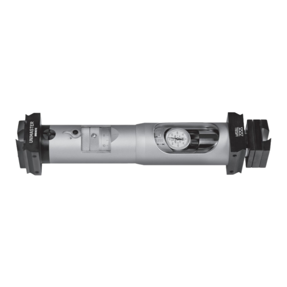
- Page 5 UNIMASTER 1 GÉNÉRALITÉS L'UNIMASTER est un instrument mécanique, à Pour la mesure, l'élément est étalonné séparé- mesure directe, pour le contrôle dimensionnel de ment à l'aide de la jauge livrée avec l'UNIMASTER pièces volumineuses. Il mesure les cotes inté- et complété ensuite par les rallonges nécessaires. rieures et extérieures jusqu'à...
- Page 6 UNIMASTER 2 ASSEMBLAGE DE L'ÉLÉMENT DE MESURE – Nettoyer les surfaces de contact de l'élément de – Adapter le sens de mesure de l'élément de mesure et de la butée fixe. mesure en enlevant la touche de mesure de la –...
- Page 7 UNIMASTER 3 MISE À ZÉRO DE L'ÉLÉMENT DE MESURE – Régler l'élément de mesure de la valeur 250 mm – Chercher le point de rebroussement et amener Mesure intérieure de l'échelle inférieure, en tournant le tambour l'indicateur (2) à zéro en tournant le tambour (3). (Fig.9) (3).
- Page 8 UNIMASTER 5 MESURE – Définir à l'aide du tableau au chapitre 7 de la Amener l'aiguille de l'indicateur au point zéro, page 7, le nombre et la longueur des rallonges par déplacement du tambour (4) et en recher- nécessaires à la mesure et les assembler selon chant le point de rebroussement.
- Page 9 UNIMASTER 6 UTILISATION DES ÉQUERRES DE SUSPENSION Les équerres de suspension facilitent la mise en Pour éviter un frottement trop élevé, des axes cy- place de l'instrument. lindriques peuvent être placée entre la pièce et les – Monter les brides de fixation (16) puis les équerres.
- Page 10 UNIMASTER 8 COMBINAISONS DE MESURE Il est recommandé d'utiliser 3 rallonges au maximum par combinaison. Jeu complet UNIMASTER Capacités, mm Combinaison de mesure Combinaison de mesure avec rallonge comprenant l'élément de mesure (E) supplémentaire de 1000 mm, mm et les rallonges, mm 225 –...
- Page 11 à compter de la date de la vente. Dans de la garantie tous les dommages dus à une utilisa- les cas justifiés de garantie, TESA SA assure à son choix tion erronée, incompétente ou négligente, à un défaut l’une des prestations suivantes: –...
- Page 13 Gebrauchsanleitung UNIMASTER Direktmessgerät für große Dimensionen...
- Page 14 UNIMASTER INHALT Allgemeines Zusammenbau des Messelementes Nulleinstellung des Messelementes Innenmessung (Abb.9) Außenmessung (Abb.10) Verlängerungen Ansetzen der Verlängerungen Trennen der Verlängerungen Messen Messungen mit versetzten Kontaktpunkten Anwendung von Stützrollen (Optionales Zubehör Nr. 01160001) Gebrauch der Aufhängewinekl Fabrikationstoleranzen Messkombinationen Lagerung und Wartung Garantie Konformitätserklärung...
- Page 15 UNIMASTER 1 ALLGEMEINES Der UNIMASTER ist ein mechanisches, direkt Für die Messung wird das Element mithilfe der messendes Gerät zur Kontrolle der Abmessungen im Satz enthaltenen Lehre separat kalibriert und großer Werkstücke. Das Gerät ist für Innen- und anschließend mit den notwendigen Verlängerungen Außenmessungen bis zu einigen Metern verwend- versehen.
- Page 16 UNIMASTER 2 ZUSAMMENBAU DES MESSELEMENTES – Sämtliche Kontaktflächen des Messelementes – Messrichtung am Messelement einstellen; Mes- und des festen Messanschlages reinigen. seinsatz am beweglichen Messanschlag ent- – Sprengring (13) durch Losschrauben der fernen und Einstellschraube in entsprechende Sprengmutter (12) (Spezialschraubenzieher ver- Richtung drehen (Abb.
- Page 17 UNIMASTER 3 NULLEINSTELLUNG DES MESSELEMENTES – Messelement auf den Wert 250 mm der unteren – Umkehrpunkt ermitteln und Messuhr (2) mittels Innenmessung Skale einstellen; Messtrommel (3) drehen. Trommel (3) auf Null stellen. (Abb.9) – Einstellschraube (9) lösen. – Spannhebel (14) anziehen. –...
- Page 18 UNIMASTER 5 MESSEN – Notwendige Verlängerungen gemäß Abschnitt 7 – Messwert ermitteln. Dieser setzt sich aus den auf Seite 7 bestimmen und an das Messelement Längen der Verlängerungen, dem Wert der Mil- gemäß Abschnitt 4 anfügen. limeterskale und der Messtrommel zusammen. –...
- Page 19 UNIMASTER 6 GEBRAUCH DER AUFHÄNGEWINEKL Die Aufhängewinkel erleichtern die Halterung des Um eine zu hohe, die Messsicherheit beein- Instrumentes während der Messung. trächtigende Reibung zwischen Messgerät und – Spannbriden (16) Stützflansche Werkstück zu vermeiden, können Rollen zwischen schrauben, Aufhängewinkel (17) befestigen. Werkstück und Aufnahmewinkel gelegt werden.
- Page 20 UNIMASTER 8 MESSKOMBINATIONEN Es wird empfohlen, nicht mehr als drei Verlängerungen für eine Messkombination zu gebrauchen. Kompletter Satz UNIMASTER Bereich, mm Messkombination einschließlich Mess- Messkombination mit Zusatverlänge- element (E) und Verlängerungen, mm rung 1000 mm, mm 225 – 250 250 – 275 250 –...
- Page 21 Elemente mit einem Stoff, falls notwendig, möglich zu erhalten. mit nicht aggressiver Flüssigkeit. 10 GARANTIE TESA verpflichtet sich im Rahmen der unten auf- Gegenstand. Jede andere Dienstleistung oder geführten Bestimmungen, jegliche Funktionsfehler Entschädigung als Garantie wird ausgeschlossen. zu beheben, die auf Fabrikationsfehlern beruhen. Die Von der Garantie ausgeschlossen sind sämtliche...
- Page 23 Instruction manual UNIMASTER Direct measuring instrument for large dimensions...
- Page 24 UNIMASTER CONTENTS General description Assembling the Measuring head Setting the measuring head to zero Internal measurement (Fig.9) External measurement (Fig.10) Extensions Adding extensions Separating the extensions Measuring Measuring with offset measuring inserts Use of roller supports(option No. 1160001) Use of the supports Manufacturing tolerances Limits on Number of extensions Note to storage and maintenance...
- Page 25 UNIMASTER 1 GENERAL DESCRIPTION The UNIMASTER is a direct measuring, mecha- Before using, the measuring head is calibrated se- nical instrument, for checking the dimensions of parately with the setting gauge supplied, then the large workpieces. Internal and external sizes up to instrument is completed by fitting the number of several metres can be measured.
- Page 26 UNIMASTER 2 ASSEMBLING THE MEASURING HEAD – Clean the contact surfaces of the measuring head – Remove the measuring arm from the mobile stop and the fixed stop. (5), and set the instrument to measure either – Using the special screwdriver provided, slacken internal or external dimensions, by turning the the nut (12) to free the snap ring (13).
- Page 27 UNIMASTER 3 SETTING THE MEASURING HEAD TO ZERO – Rotate the barrel (3) to give 20 mm on the scale. rect contact point is found by observation of the Internal measurement – Slacken the setting screw (9). dial gauge (2). Rotate the barrel (3) to bring the (Fig.9) –...
- Page 28 UNIMASTER 5 MEASURING – Use the table of chapter 7 on page 7 to decide the and find the correct contact point as already des- number and lengths of the extensions necessary, cribed. Rotate the barrel (4) until the dial gauge and assemble as described in chapter 4.
- Page 29 UNIMASTER 6 USE OF THE SUPPORTS The supports simplify the measuring operation, – If necessary, steel cylinders can be placed on the especially when gauging very wide distances. workpiece, and the measuring arms supported – Fit the clamps (16) and introduce the measuring on these to decrease friction while setting to arms (17).
- Page 30 UNIMASTER 8 MEASURING COMBINATIONS It's recommended to use three extensions at the maximum. Complete UNIMASTER Set Range, mm Measuring combination with measu- Measuring combination using supple- ring element (E) and extensions, mm mentary extension 1000 mm, mm 225 – 250 250 –...
- Page 31 TESA SA shall choose one to comply with service instructions,or any other of the following services: – free repair by TESA or hazard, including cases of force majeure. a TESA-certified service shop, or – free replace- (Extract from our general sales conditions 2012 ment, or –...
- Page 32 TESA Technology Bugnon 38 – CH-1020 Renens – Switzerland Tél. +41(0)21 633 16 00 – Fax +41(0)21 635 75 35 www.tesatechnology.com – tesa-info@hexagon.com Imprimé en Suisse – Toutes modifications réservées – 1199.002.1908 – ME1199002...
Need help?
Do you have a question about the HEXAGON UNIMASTER and is the answer not in the manual?
Questions and answers