
Related Manuals for TESA MH3D


Summary of Contents for TESA MH3D
- Page 1 U S E R ' S M A N U A L English User's Manual Page 0-1 MH3D ©2004 TESA Switzerland All Rights Reserved.
- Page 2 User's Manual Page 0-2 MH3D ©2004 TESA Switzerland All Rights Reserved.
-
Page 3: Table Of Contents
Probes .................... 2-14 TESASTAR Probe ................ 2-14 TESASTAR_I Probe ..............2-14 Electronic System ................2-15 Controller ..................2-16 MH3D Rear Connections .............. 2-17 MH3D Control Box............... 2-17 Cables .................... 2-18 CHAPTER 3 - Operation ..............3-1 Operator Safety ................3-3 Using a Desk Mouse................ - Page 4 CHAPTER 5 - Glossary ..............5-1 CHAPTER A - Video Optical Probe ..........A-1 Installation ..................A-3 Mounting Configuration ..............A-4 Connecting Diagram............... A-5 Adjustments ..................A-6 Qualification ................... A-8 Measuring ..................A-9 User's Manual Page 0-4 MH3D ©2004 TESA Switzerland All Rights Reserved.
-
Page 5: Chapter 1 - Introduction
CHAPTER 1 Introduction User's Manual Page 1-1 MH3D ©2004 TESA Switzerland All Rights Reserved. - Page 6 User's Manual Page 1-2 MH3D ©2004 TESA Switzerland All Rights Reserved.
-
Page 7: Foreword
The MH3D is designed to meet production needs and to produce speedy, accurate and economical verification of a variety of work pieces. -
Page 8: Warranty
LOST PROFITS OR OTHER DAMAGES FROM LOSS OF PRODUCTION) CAUSED BY DEFECTIVE MATERIAL, OR BY UNSATISFACTORY PERFORMANCE OF THE PRODUCT, OR BY ANY OTHER BREACH OF CONTRACT BY US. User's Manual Page 1-4 MH3D ©2004 TESA Switzerland All Rights Reserved. -
Page 9: Warranty Service
In the event that you should require information or service assistance for your MH3D, it is recommended that you call the dealer from whom the machine was purchased or one of the TESA regional offices. Due to the complexity of this machine, we recommend only TESA factory authorized service centers be used. -
Page 10: General Safety
General Safety This manual should be read in its entirety by all supervisory and operating personnel before installation, operation and maintenance. The MH3D has been designed to minimize possible hazards to the operator and sources of damage to the machine. While it is impossible to anticipate every situation, strict adherence to the safety rules in this manual will reduce the possibility of injury to personnel and damage to the machine. -
Page 11: Description
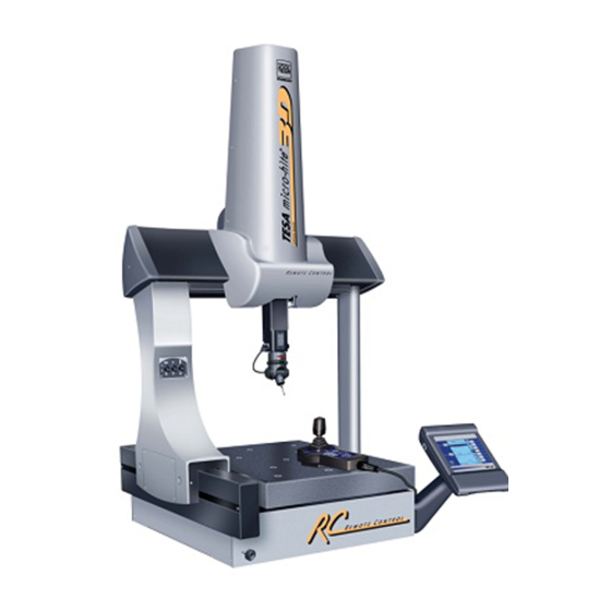
Description The MH3D Machine The MH3D Coordinate Measuring Machine features a lightweight, table top, bridge type design with a removable granite support. This machine is designed to accommodate moderate sized work pieces with an economical table mounted unit. This series of machines incorporates the following features: •... - Page 12 Description 6-13 The MH3D System consists of the following main components: 11. Control Box and VGA Monitor 1. Base 12. Stand (optional) 2. Granite Table 13. ZMouse 3. Y-Axis Rails 14. Air Supply (rear) 4. Bridge 15. Air Bearings (not visible) 5.
- Page 13 8. COUNTERBALANCE ADJUST KNOB -This knob is used to adjust the counterbalance cylinder for the varying probe weights. 9. AXIS LOCK SWITCHES - On the MH3D the switches are used to engage or release the fine adjust mechanism. 10. PROBE - Probes are either hard or touch trigger types and are used to take measurements on the piece being measured.
- Page 14 They are also used to level the granite to the X and Y axes. 20. FINE ADJUSTMENT - Allows precise adjustment of all three axes by means of knurled knobs .(Optional) User's Manual Page 1-10 MH3D ©2004 TESA Switzerland All Rights Reserved.
-
Page 15: Dimensions
Dimensions MH3D MEASUREMENTS ARE LISTED ON THE SPECIFICATIONS SHEETS User's Manual Page 1-11 MH3D ©2004 TESA Switzerland All Rights Reserved. -
Page 16: Specifications
* Machine range when using 75 mm (3.0") long probe. Repeatability, Volumetric and Linear Accuracy is measured with a 325mm (12.8") Ball Bar in the center of machine sytem certified. User's Manual Page 1-12 MH3D ©2004 TESA Switzerland All Rights Reserved. -
Page 17: Chapter 2 - Construction
CHAPTER 2 Construction User's Manual Page 2-1 MH3D ©2004 TESA Switzerland All Rights Reserved. - Page 18 User's Manual MH3D Page 2-2 ©2004 TESA Switzerland All Rights Reserved.
-
Page 19: Base
1mm-1.5mm (.040"-.060") clearance above the top of the bench. These bolts prevent the MH3D from tipping, if it should be bumped or loaded in an unbalanced condition. Note: These anti-tip bolts Must Not touch the bench under normal conditions. -
Page 20: Work Table
Maximum torque is 20.5 Nm. The work table should be kept clean by wiping with alcohol, particularly when this surface is being used as a datum. User's Manual MH3D Page 2-4 ©2004 TESA Switzerland All Rights Reserved. -
Page 21: Y-Rails
It is very important that the rails be kept clean and not be bumped when parts are loaded and unloaded. Never lift the MH3D by the Y-Rails. Note: Although the guide... -
Page 22: Bridge
Bridge The MH3D is a vertical, moving bridge type of CMM. The Bridge travels along the Y-rail at a right angle to the front of the machine. It is of modular construc- tion and consists of a left outboard leg, a right inboard leg and an X-Rail which spans the two legs. -
Page 23: Zx Carriage
X direction. A large knurled knob at the bottom of the carriage is used for the precise adjustment of the Z-rail. User's Manual Page 2-7 MH3D ©2004 TESA Switzerland All Rights Reserved. -
Page 24: Z Rail
The machine is prewired to accept the optional Touch Trigger Probe. A cable is assembled thru the center of the Z-rail with a socket at the lower end of the rail for electronically connecting the Touch Trigger Probe. User's Manual MH3D Page 2-8 ©2004 TESA Switzerland All Rights Reserved. -
Page 25: Air Control And Filter
Hold the Z-rail firmly as it may move suddenly when the brake unlocks. On the MH3D machine the air switches are used both as axis locks and also to engage and release the fine adjust mechanism. The fine adjust mechanisms are used for precisely adjusting the machine's three axes. -
Page 26: Air System
F > droite right (Axe Y) bottom bottom bottom left left (049746) bottom 4,0 bar (58 psi) = 8 mm = 4 mm = 4 mm 4,8 bar (70 psi) User's Manual MH3D Page 2-10 ©2004 TESA Switzerland All Rights Reserved. -
Page 27: Air Bearings
Air Bearings Twenty-two (22) air bearings are used on the MH3D to provide virtually friction- less, noncontact travel along the respective axes. Air supplied to the bearings is forced through an orifice in the active surface and is uniformly distributed throughout the surface by a system of grooves. -
Page 28: Measuring System
Measuring System The measuring system on the MH3D features glass scales which are etched alternately of lines and spaces of equal width. The glass scales are firmly mounted to each of the axes rails. These mountings allow the scale to expand and contract along with the machine. -
Page 29: Reference Offsets
• Values were measured from the center of the hole in the bottom of the probe holder in the MH3D. Values are in terms of machine coordinates. • All values were measured with the probe detent engaged in the probe holder. -
Page 30: Probes
Probes TESASTAR Probe Shank Dia. 9,5 mm 047714 Star Knob 047778 Probe body 047783 Probe Stylus 03969042 TESASTAR 03939020 TESASTAR_I Probe User's Manual MH3D Page 2-14 ©2004 TESA Switzerland All Rights Reserved. -
Page 31: Electronic System
Measurement points can also be taken by deflecting an electronic probe (TTP) on the part surface. User's Manual Page 2-15 MH3D ©2004 TESA Switzerland All Rights Reserved. -
Page 32: Controller
Controller The MH3D control box is a shop-hardened control unit with the following: • A power switch under the front left edge of the console • A MH3D Software Card • A PCMCIA "Smart Card" for storing programs • A 32-bit RISC processor •... -
Page 33: Mh3D Rear Connections
Controller MH3D Rear Connections MH3D Control Box User's Manual Page 2-17 MH3D ©2004 TESA Switzerland All Rights Reserved. -
Page 34: Cables
Cables Printer Power supply User's Manual MH3D Page 2-18 ©2004 TESA Switzerland All Rights Reserved. -
Page 35: Chapter 3 - Operation
CHAPTER 3 Operation User's Manual Page 3-1 MH3D ©2004 TESA Switzerland All Rights Reserved. - Page 36 User's Manual Page 3-2 MH3D ©2004 TESA Switzerland All Rights Reserved.
-
Page 37: Operator Safety
Never operate the machine when its guards are removed. The MH3D has been designed to minimize possible hazards to the operator and sources of damage to the machine. While it is impossible to anticipate every situation, strict adherence to the safety rules in this manual will reduce the possibility of injury to personnel and damage to the machine. - Page 38 Before mounting work holding devices or workpieces, be sure that all mounting surfaces are clean and free of chips. • It is good practice to avoid loading and unloading parts over the rails. User's Manual Page 3-4 MH3D ©2004 TESA Switzerland All Rights Reserved.
- Page 39 • Keep hands away from all guards and openings in covers when moving the bridge or carriage. • Tables, rails, housings and their related parts can create pinch points. Be sure you are clear of such locations before operating the MH3D. • Never remove WARNING and/or INSTRUCTION plates from the machine.
-
Page 40: Using A Desk Mouse
For right handed mice, Button 1 is the leftmost button. This button is used to select button icons on the screen. Button 2: For right handed mice, Button 2 is the center button. On MH3D this button is not used. Button 3: For right handed mice, Button 3 is the rightmost button. -
Page 41: Using A Zmouse
Scan/Abort The Scan/Abort button is used to initiate scanning witha hard probe, and as an Abort/Escape function Select when using a TTP. Cursor Movement User's Manual Page 3-7 MH3D ©2004 TESA Switzerland All Rights Reserved. -
Page 42: Starting & Stopping
If the pressure is not correct, unlock the knob at the bottom of the regulator, adjust the pressure, and relock the knob. • All cables from the machine to the MH3D controller (ie. encoder, ground, ZMouse and, if included, TTP, etc.) are connected (reference the schemtatics). - Page 43 • Plug the power cord for the power supply into an outlet that agrees with the specifications in the Installation Manual. • Power up the machine. For the MH3D controller, push the front panel rocker switch located on the front, left edge of the MH3D control box.
-
Page 44: Moving The Axes
On the MH3D, the axes can be precisely adjusted by means of a rod and bearing arrangement that acts like a fine pitch screw. The rod is turned by means of large, knurled knobs mounted on both ends of the X-axis and Y-axis and at the lower end of the Z-axis. -
Page 45: Homing The Machine
Homing the Machine The home position for the MH3D is in the upper front left corner of the machine. Before any measurements can be made, the machine must be moved to its home position and that position must be recorded in the software. This is so that the machine has a reference position to which it can relate all axes movements. -
Page 46: The Inspection Process
• Ensure that the part to be measured does not exceed the machine’s weight or size capacity. • Locate the part within the measuring envelope of the MH3D, ensuring that the sections to be measured are within the probe measuring range and as close to the operator as possible. -
Page 47: Probe Installation
The procedure for installing your probe may differ from these. Refer to your probe manufacturer's documentation for installation instructions. Note: Each tip must be qualified before it it used for measurements. User's Manual Page 3-13 MH3D ©2004 TESA Switzerland All Rights Reserved. -
Page 48: Measuring With A Ball Probe
After the first point is taken, it is OK to slide the probe on the feature’s surface between taking points. User's Manual Page 3-14 MH3D ©2004 TESA Switzerland All Rights Reserved. -
Page 49: Probe Compensation
Taking Points With a Hard Probe on a Round Surface The approach vector for the first point for a round surface Points taken after should be radial. the intial point can be tangential to the round surface. User's Manual Page 3-15 MH3D ©2004 TESA Switzerland All Rights Reserved. -
Page 50: Measuring With An Electronic Probe
Skidding (probe tip sliding on the part as probe contacts are disturbed) produces inconsistent and non-repeatable results. If probe hits are taken within 20 degrees of perpendicular, skidding errors will be much less than one micron (0.000040 in.). User's Manual Page 3-16 MH3D ©2004 TESA Switzerland All Rights Reserved. -
Page 51: Touch Trigger Probe Repeatability
Parallel to the Probe Body (Along axis Stylus of stylus) Knuckle Very Low Repeatablility (should be avoided) Neither Perpendicular nor Parallel to the Probe Body but along the axis of stylus User's Manual Page 3-17 MH3D ©2004 TESA Switzerland All Rights Reserved. - Page 52 The stylus ruby tip should always be kept free of contaminants. A one micron (0.000040 inch) piece of grime causes a one micron measurement error. Correct Probe Contact Shanking Shanking User's Manual Page 3-18 MH3D ©2004 TESA Switzerland All Rights Reserved.
- Page 53 User's Manual Page 3-19 MH3D ©2004 TESA Switzerland All Rights Reserved.
-
Page 54: Useful Probe Dimensions
Useful Probe Dimensions TESASTAR_i User's Manual Page 3-20 MH3D ©2004 TESA Switzerland All Rights Reserved. -
Page 55: Good Measurement Techniques
Good Measurement Techniques The following are good techniques to use when operating the MH3D: • Operators should qualify their own tips because of differences in style. • Verify probe offsets after qualification. • Clamp the part so that it doesn't move when measuring. - Page 56 MH3D Notes User's Manual Page 3-22 MH3D ©2004 TESA Switzerland All Rights Reserved.
-
Page 57: Chapter 4 - Maintenance
CHAPTER 4 Maintenance User's Manual Page 4-1 MH3D ©2004 TESA Switzerland All Rights Reserved. - Page 58 User's Manual Page 4-2 MH3D ©2004 TESA Switzerland All Rights Reserved.
-
Page 59: General Safety Practices
Safety Proper maintenance, on a regular scheduled basis, is vitally important in a plant safety program. You should be thoroughly familiar with the MH3D, including its controls, safety devices, and operation, before attempting any maintenance work. Since maintenance work often necessitates working on a machine with safety guards and covers removed, you should approach every job with the proper respect for established safety procedures. -
Page 60: Electronics
Serious damage to the machine will result. • Before repressurizing the system after maintenance, be sure the main air line is securely attached to the air supply system inlet port. User's Manual Page 4-4 MH3D ©2004 TESA Switzerland All Rights Reserved. -
Page 61: Maintenance Intervals
Some inspections and adjustments require the Main Power to be in the ON position to provide necessary power. In such cases, use extreme caution to prevent injury and machine damage. User's Manual Page 4-5 MH3D ©2004 TESA Switzerland All Rights Reserved. -
Page 62: Daily Or Every 8 Hours
Hazardous Voltages exist inside the electronic cabinet. Service must be performed by trained, authorized personnel only. Use extreme caution in making tests and adjustments. Safety glasses should be worn while servicing the electronic cabinet. User's Manual Page 4-6 MH3D ©2004 TESA Switzerland All Rights Reserved. -
Page 63: Maintenance Log
Check electronic probes and cables Check measuring scales Check air system Check that the machine is level Three Months Check air system lines Check all machine functions Check electronics Check cable connections User's Manual Page 4-7 MH3D ©2004 TESA Switzerland All Rights Reserved. -
Page 64: Machine Troubleshooting
Machine won’t turn on • Is the power cord plugged in? • Is the voltage supply correct? • Is power supplied to the receptacle? • Is the power switch on? User's Manual Page 4-8 MH3D ©2004 TESA Switzerland All Rights Reserved. - Page 65 If the light remains off after a hit has been taken, gently move the stylus or the probe with your finger. The probe light should turn back • Are the machine and control box cables correct and properly connected? User's Manual Page 4-9 MH3D ©2004 TESA Switzerland All Rights Reserved.
-
Page 66: Troubleshooting
• Check to ensure that the air pressure for the machine is set to 55 psi. • If the machine air pressure is set to 55 psi, consult TESA for help. Oil appears from under the air bearings • Clean the rails as described in “Cleaning the Bearing Surfaces”... -
Page 67: Cleaning Glass Scales
Cleaning Glass Scales If it is necessary to clean the glass scales on the MH3D, proceed as follows: Cleaning the X Axis Scale • Move the bridge to the rear of the machine. X Scale • Move the ZX cariage to one end of its travel. -
Page 68: Changing The Air Filter
• If the filter gets dirty fairly quickly, place another air filter/regulator upstream of the machine. • If excessive water is present within the air system at your facility use a Refrig- erated Air Dryer User's Manual Page 4-12 MH3D ©2004 TESA Switzerland All Rights Reserved. -
Page 69: Chapter 5 - Glossary
CHAPTER 5 Glossary User's Manual Page 5-1 MH3D ©2004 TESA Switzerland All Rights Reserved. - Page 70 User's Manual Page 5-2 MH3D ©2004 TESA Switzerland All Rights Reserved.
- Page 71 Append To add to an existing part program. Applications Software that provides the computer with instructions Software for a specific task, such as inspecting a part. User's Manual Page 5-3 MH3D ©2004 TESA Switzerland All Rights Reserved.
- Page 72 Bolt Circle A measurement routine which constructs a circle through previously measured circle center points. User's Manual Page 5-4 MH3D ©2004 TESA Switzerland All Rights Reserved.
- Page 73 (working plane) between 2 circle center points. Circularity The condition of a circle as it lies in a tolerance zone formed by two concentric circles. Also called roundness. User's Manual Page 5-5 MH3D ©2004 TESA Switzerland All Rights Reserved.
- Page 74 Cylinder A circular three dimensional space. A minimum of five points are required to define a cylinder. User's Manual Page 5-6 MH3D ©2004 TESA Switzerland All Rights Reserved.
- Page 75 A storage device used to store part programs and other data collected by the computer. Disk Drive A device used to read and write information from the computer to a disk. User's Manual Page 5-7 MH3D ©2004 TESA Switzerland All Rights Reserved.
- Page 76 Denotes the menu level feature name, such as Circle, Point, etc. File An organized collection of information stored in the computer as a unit. File Name A name used to store a file in the computer. User's Manual Page 5-8 MH3D ©2004 TESA Switzerland All Rights Reserved.
- Page 77 Can only be used with manual machines. Hardware The physical components of a computer system, includ- ing the CPU, keyboard, disk drive, monitor and printer. User's Manual Page 5-9 MH3D ©2004 TESA Switzerland All Rights Reserved.
- Page 78 To manually inspect a part with all moves and measure- ments being saved for future use under a specifically named program. Least Square The interpolation of a function to all points in a given Method data set. User's Manual Page 5-10 MH3D ©2004 TESA Switzerland All Rights Reserved.
- Page 79 X is the first-named axis and Y is the second-named axis. The Unnamed Axis is the axis not named in the working plane, in this case Z. User's Manual Page 5-11 MH3D ©2004 TESA Switzerland All Rights Reserved.
- Page 80 A point in the machine’s work zone at which machine coordinates are recorded as part of a measurement. Measurement The instruction program that tells the computer how to Software calculate the measurement data. User's Manual Page 5-12 MH3D ©2004 TESA Switzerland All Rights Reserved.
- Page 81 Multiplier A value that effectively pushes the target point deeper into the part. Named Axes The two axes of the machine’s working plane. Same as Machine Named Axes. User's Manual Page 5-13 MH3D ©2004 TESA Switzerland All Rights Reserved.
- Page 82 Origin The zero point or center of the current coordinate system and alignment. It is a designated reference point for all measurements taken of the part. User's Manual Page 5-14 MH3D ©2004 TESA Switzerland All Rights Reserved.
- Page 83 Periodic Error An error in the linear displacement accuracy of a ma- chine that is periodic over an interval which normally coincides with a natural period of the machine scales. User's Manual Page 5-15 MH3D ©2004 TESA Switzerland All Rights Reserved.
- Page 84 Polar Radius The line that measures the distance from zero point to the located point in polar coordinates. User's Manual Page 5-16 MH3D ©2004 TESA Switzerland All Rights Reserved.
- Page 85 A cross-section of a part, projected into some reference plane. Program Listing A line-by-line list on the computer screen or on a printout showing the steps in a part program. User's Manual Page 5-17 MH3D ©2004 TESA Switzerland All Rights Reserved.
- Page 86 Repeatable Socket A socket that allows the accurate repositioning of one end of a ball bar. User's Manual Page 5-18 MH3D ©2004 TESA Switzerland All Rights Reserved.
- Page 87 A modifier to a feature that defines a specific characteristic. Screen The video display on a computer. Seating Probe A hard probe that will maintain its location with respect to a measurement point without operator contact. User's Manual Page 5-19 MH3D ©2004 TESA Switzerland All Rights Reserved.
- Page 88 A sphere is defined by at least four points. Spherical Expressing a point in space by its (r, phi, rho) in relation Coordinates to some fixed origin. User's Manual Page 5-20 MH3D ©2004 TESA Switzerland All Rights Reserved.
- Page 89 The datum established by at least one point of contact between a datum feature and the inspection surface. Tolerance Limiting values added to nominal dimensions that allow variations of a measured feature. User's Manual Page 5-21 MH3D ©2004 TESA Switzerland All Rights Reserved.
- Page 90 In the case of a plane, the vector is orthogonal to the measured surface, pointing in the direction from which the plane was probed. Vibration Amplitude Peak-to-peak amplitude of a given frequency component. User's Manual Page 5-22 MH3D ©2004 TESA Switzerland All Rights Reserved.
- Page 91 Zero Point The point in a coordinate system where the X, Y, and Z axes intersect. Z Rail The vertical moving component that holds the probe. Also called Z Ram. User's Manual Page 5-23 MH3D ©2004 TESA Switzerland All Rights Reserved.
- Page 92 MH3D Notes User's Manual Page 5-24 MH3D ©2004 TESA Switzerland All Rights Reserved.
- Page 93 CHAPTER A Appendix User's Manual Page A-1 MH3D ©2004 TESA Switzerland All Rights Reserved.
- Page 94 User's Manual Page A-2 MH3D ©2004 TESA Switzerland All Rights Reserved.
-
Page 95: Installation
When not in use it should be stored in its original foam lined box with the protective cap on the objective lens. To install the optical video probe on the MH3D refer to the mounting configuration and the connecting diagram and proceed as follows: 1. -
Page 96: Mounting Configuration
RAM Optical Probe - Installation Mounting Configuration User's Manual Page A-4 MH3D ©2004 TESA Switzerland All Rights Reserved. -
Page 97: Connecting Diagram
RAM Optical Probe - Installation Connecting Diagram User's Manual Page A-5 MH3D ©2004 TESA Switzerland All Rights Reserved. -
Page 98: Adjustments
(parfocal) throughout the zooming range as follows: 1. Focus on a part or on the MH3D's granite table using the probe's highest magnification. 2. Zoom to the lowest magnification while observing the image on the monitor screen. - Page 99 Crosshair Alignment It is recommended that the crosshairs on the monitor screen be aligned to the X-axis and Y-axis of the MH3D. To align the crosshairs: 1. Lock the Y-axis. 2. Using a sharp pencil, draw a line on the surface of the granite by holding the pencil tight to the Z-rail and moving the ZX carriage along the X-axis.
-
Page 100: Qualification
CCD Optical Probe - Qualification Note: In order to use a RAM Optical Probe with MH3D you will have to install a desk mouse in addition to the ZMouse. This is because the RAM Optical Probe covers the buttons of the ZMouse. Select the "System Options" softkey and the "Languages, etc."... -
Page 101: Measuring
It is helpful to consider the optical probe as a solid ball with a ball diameter of zero or as an edge probe. You must "tell" the MH3D software when to record the coordinates of the selected point on the part surface. This is done by pressing the right hand button on the desk mouse. - Page 102 4. Focus on the bottom plane of the feature and take a single measurement point. Press "Done". 5. The lower section of the screen now displays the distance along Z. Use the highest practical magnification during this procedure for the best accuracy. User's Manual Page A-10 MH3D ©2004 TESA Switzerland All Rights Reserved.
Need help?
Do you have a question about the MH3D and is the answer not in the manual?
Questions and answers