
Related Manuals for TESA Micro-Hite Plus M


Summary of Contents for TESA Micro-Hite Plus M
- Page 1 Instruction Manual TESA Micro-Hite ® Plus M Base instrument, 1D Control Panel and Accessories...
-
Page 3: Table Of Contents
General cleaning page 42 Recharging batteries page 42 Changing worn-out batteries page 42 Delivery programme page 43 TESA Micro-hite plus M height gauges page 43 Control panels page 44 Optional accessories page 45 Technical data page 50 RS 232 digital interface... -
Page 4: General Features
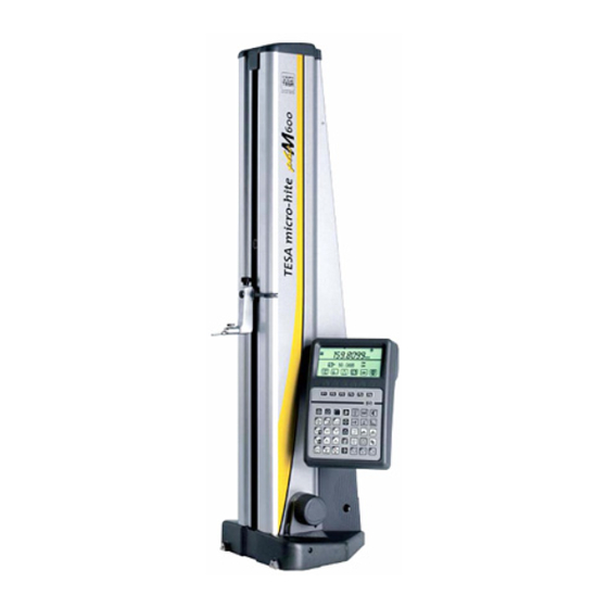
1 GENERAL FEATURES Cover plate 1 Transmission band 2 Housing 3 9 Handle 10 1D control panel Mounting pin 4 Probe fixing arm 5 Probe 6 13 Setting screw for air-cushion 11 Switch for electric pump 12 Rotary power control 8 Three-point cast-iron base Guiding face with resting points 7 Fig. - Page 5 1 GENERAL FEATURES All TESA Micro-hite plus M of the latest generation The heavy cast-iron base features three resting are different from the other height gauges in that points precisely ground to ensure high stability. they have exceptional metrological capabilities and Once integrated, the electric pump generates the can be used intuitively with ease.
-
Page 6: Installation
2 INSTALLATION TESA Micro-hite plus M is supplied in a special – Stand the instrument up on the clear surface Unpacking and box giving protection against shocks and corrosion. plate. setting up Keep this box for use whenever the instrument is –... - Page 7 00760221) Probe insert moves automatically, travels past the reference mark of the precision glass scale for initialisation, then places itself into position at the centre of the master piece. Access mode Is TESA IG-13 for perpendicularity connected? measurement? Probe constant...
-
Page 8: Key Components
The faces 7 (Fig.1, page 4) are specially designed to Height gauge corrosion. The precision ground bottom face allow TESA Micro-hite plus M to rest on or be base includes three supporting points which are finely guided in straight-line along the length of a rule, for lapped to guarantee high stability to your TESA instance. - Page 9 Operating functions using the rotary power control Usually, these functions are identical to those of the probe insert. Ways to move the probe insert – Turn the rotary power control clockwise to move it up (Fig. 1). – Turn the rotary power control counterclockwise to move it down (Fig.
- Page 10 Bore measurement A second short rotation of the power control in the same direction permits bore measurement with detection of the culmination point. – Turn the power control clockwise to start probing the upper point. – Turn the rotary power control counterclockwise, to start probing the lower point first.
-
Page 11: Power Supply
4.13. position errors of the head guides. Length values are corrected based on the actual TESA Micro-hite plus M is able to execute the auto- deviations previously determined step by step at matic correction of the measured values through each probing point throughout the measuring range CAA (computer-aided accuracy) while taking bias using reference gauge blocks. -
Page 12: Control Panels
O F F PRI N T ÷ 4 MEASURING The way TESA Micro-hite plus M will execute a – Measuring perpendicularity and straightness General value acquisition often depends on the measuring with the aid of TESA IG-13 probe (only with application, which is mainly based on the following: connected Power Panel Plus M). - Page 13 Measuring without inversion of the probing direction Making no allowance for the probe constant Measuring with inversion of the probing direction Making allowance for the probe constant – with no storage of the culmination point – with storage of the culmination point Capturing form and position errors Parallelism Radial...
-
Page 14: Control Panel With Function Keys
Press shortly (< 6 s) to probe up. 1D control panel Keep pressing this key (>0,6 s) to move with function keys the probe up quickly (30 mm/s). Probe will (N° 00760216) stop moving as soon as you release it. Press to probe up with detection of the highest culmination point. - Page 15 0.1 µm/0.00001¨ Ext. P = Print Auto 7,5 mm/s Print manual 1 µm/0.0001¨ Ext P = Print 1, 2, n 15 mm/s Measure auto Data French German English Spanish Italian Portuguese Swedish SW10 Dip switch settings Resolution selection (0.1 µm / 1 µm). Probe speed switches over from 7,5 to 15 mm/s before starting measuring.
-
Page 16: Power Panel Plus M With Function Keys
Press to enable mean value from the last Power Panel Plus M two probe contacts or from both num- with function keys bered values selected in the logbook to be (N° 00760220 or calculated and further displayed. 00760221) ÷ Press to cancel both references A and B and return to menu St1/2 to take a new ref- erence A and/or B along with probe con- stant if you wish to. -
Page 17: Probing Procedure At The Contact Point
Press to measure both the centre and Press to enter in statistics menu. diameter of a shaft. Press to enter in configuration menu. Press ENTER to validate your operation. Press to enter in menu for executing Press for value capture from the measur- a programme. - Page 18 Probe contact procedure for value acquisition 1 Move both measuring head and probe insert quickly using the rotary power control or the han- dle 9. You may also enable fast displacement through the keyboard. 2 Position the insert close to the point to be probed. The rotary power control must then regain its neutral position ( ).
- Page 19 4 Constant measuring force is ensured by the fric- tion mechanism as soon as the insert is contact- ing the relevant point. After a wait for stabilisa- tion, the measured value will be registered and further displayed via the control panel. Stabilisation related criteria: with a resolution to 0,1µm: variation <...
-
Page 20: Establishing The Probe Constant
This piece has been specially designed for use with Establishing probe measured with inversion of the probing direction, TESA Micro-hite plus M. The reason for this new constant for length the probe constant has to be taken into account. feature was to reduce the error resulting from the... - Page 21 Probe insert moves into position at the centre of the mark or probe constant key has been activated. master piece automatically as soon as either of the TESA Micro-hite plus M then displays the measured following conditions is met: height gauge is value as shown below.
-
Page 22: Programming Retraction Travel
Displaying after probe constant acquisition When the function for temperature correction has been enabled, the measured temperature value will only be displayed on the Power Panel plus M along with relevant symbol. To prevent excess wearing, the probe insert retracts turing a reference value from menu St1/2. -
Page 23: Capturing A Reference Value
If you press either of these keys within less two probe contacts. than 3 seconds, – TESA Micro-hite plus M will repeat the same func- Examples tion at the new location If you move the probe 1 When activating one of these functions keys insert by rotating the power control. - Page 24 Enabling keys/gauge Displaying Explanation At this point, probing procedure will stop if none of the keys available for fast displacement is activated. Second probe contact will not be executed unless you press either function key again. Reference value will match the mean calculated from the two probe contacts.
-
Page 25: Preset Mode
Enabling keys/gauge Displaying Explanation Reference value obtained from the two probe contacts. Fonction PRESET Enter a PRESET value in relation to an indirect ref- erence through numerical keys (e.g. 50,2 mm). PRESET value is introduced. - Page 26 Activating keys/Instr. Displaying Explanation Capture reference value. Cancel PRESET value. Input zero value by pressing ENTER key twice. Follow the same procedure for entering a PRESET value in either of both modes St1 or St2.
-
Page 27: Measuring Grooves
Enabling keys/gauge Displaying Explanation Measuring grooves Probe contact procedure. Position probe insert into the groove by pressing both positioning keys or rotating the power control. Probe moves up automatically for capturing first value. Auxiliary display shows probe displacement, continuously. First value is being captured with simultaneous dis- playing of related symbol. - Page 28 Enabling keys/gauge Displaying Comments Probing procedure is ended. Probe retraction occurs automatically. Values are normally displayed. Difference between both probe contacts is shown on the main display for a while. Numbered value is incremented providing dip switch 6 is set on ON Difference between both probe contacts is perma- nently shown on main display.
-
Page 29: Measuring Ribs
Enabling keys/gauge Displaying Explanation 4.10 Measuring ribs Probe contact procedure. Position probe insert below the rib by pressing both positioning keys or rotating the power control Probe moves up automatically for capturing first value. Auxiliary display shows probe displacement, continuously. First value is being captured with simultaneous dis- playing of related symbol. -
Page 30: Measuring Bores
Enabling keys/gauge Displaying Explanation Probe contact procedure is completed. Probe insert retracts automatically. Measured values are normally displayed. Main display shows the difference between both probe contacts for a while. Numbered value is incremented providing dip switch 6 is set on ON Main display shows the difference between both probe contacts permanently. - Page 31 Enabling keys/gauge Displaying Explanation Release measurement cycle by pressing function or shortly rotating the power control twice in the direction you wish probe contact to be started. Starting probing operation As probe insert is moving, display shows its dis- placement continuously. Probe symbol appears as soon as the insert has stabilised after contacting the workpiece feature.
-
Page 32: Measuring Shafts
Enabling keys/gauge Displaying Explanation Main display shows the difference between both probe contacts for a while. Numbered value is incremented providing dip switch 6 is set on ON. Main display shows the difference between both probe contacts permanently. Displayed values will not be retained in memory once the height gauge has been switched off. - Page 33 Enabling keys/gauge Displaying Explanation Once first measurement cycle has been completed, probe insert moves clear of the workpiece automat- ically, then stands still. Use both relevant keys or the rotary power control for correct positioning of the insert above the given diameter. Start second measurement cycle by pressing ENTER or rotating the power control.
-
Page 34: Calculating Distances
Enabling keys/gauge Displaying Explanation 4.13 Calculating distances Display shows calculated distance between the last two measured workpiece features. At this point, there are three ways of proceeding 2 Store numbered value M09 by pressing key provided automatic numbering is activated (dip 3 Calculate another distance (M? - M?) by pressing switch 6 on On): function key... - Page 35 Enabling keys/gauge Displaying Explanation Enter second numbered value through numerical keys (e.g. 06), then confirm by pressing ENTER. Bright sign _ following second letter M will blink. At this stage, you may either let another distance be calculated by pressing key or a new measure- ment be taken.
- Page 36 Enabling keys/gauge Display Explanation Press both keys to display all num- bered values subsequently. Press ENTER to confirm. Ready for entering second numbered value. Bright sign _ following second letter M will blink. Enter relevant value number, then press ENTER to confirm.
-
Page 37: Measuring Centre Distances Of Threads
During the probing operations, the probe axis must be, as far as possible, parallel to that of the thread to be inspected. Consequently, TESA Micro-hite plus M has to be positioned very carefully. -
Page 38: Measuring Flatness Or Parallelism On Flat Surfaces
Enabling keys/gauge Displaying Explanation 4.15 The mode enabling both MAX/MIN To leave this menu and return to the reference mode Measuring flatness points to be detected can be accessed previously quitted, press the function key or parallelism on from any position by simply activating flat surfaces function key Use relevant keys or the rotary power control for... - Page 39 Enabling keys/gauge Displaying Explanation Display shows MAX minus MIN value. Display shows MAX value. Display shows MIN value. To quit MAX/MIN mode and return to measuring mode, press function key . References that were active before entering in the MAX/MIN mode will be activated again. If automatic numbering is enabled (dip switch 6 set on ON), displayed values MAX minus MIN, MAX and MIN will be successively registered as M09,...
-
Page 40: Measuring Deviations From Perpendicularity Using A Dial-Test Indicator
13 mm / 0.51 in probe and straightness. It cannot be used in conjunction Signal resolution 0.0005 mm with a TESA Micro-hite plus M unless it is linked to Accuracy 1 µm the Power Panel plus M. The measuring configura- Measuring force 0,45 N (at zero) tion is pictured in Fig. - Page 41 In this case, the perpendicularity error as measured following directions: «frontal», «lateral on the left» on your TESA Micro-hite plus M will match the limit or «lateral on the right». Therefore, each TESA values stated in chapter 7 – Technical data.
-
Page 42: Maintenance
5 MAINTENANCE To get the most of your TESA Micro-hite plus M you respected (see chapter 7 – Technical data). When will need to choose a place where the limit values not in use, we recommend to protect your height given for operating and storage temperature are gauge with the dust cover supplied. -
Page 43: Delivery Programme
0 à 1300 mm with insert-holder S07001622 / 29 in / 39 in / 51 in Each TESA Micro-hite plus M base set consists of the following components: 1 TESA Micro-hite plus M 350 or 00730060 TESA Micro-hite plus M 600 or 00730061... -
Page 44: Control Panels
– RS232 serial interface for bi-directional data transmission. – Input for a measuring instrument with RS232 digital output. – Input for a TESA IG-13 digital probe. – Input for the foot switch used for triggering PRINT function or repeat last measurement ÷... -
Page 45: Optional Accessories
Measuring insert Measuring insert Optional With tungsten carbide measuring face (convex) With disc-shaped, tungsten carbide measuring accessories for inspecting cylindrical bores or establishing face for measuring grooves, turned grooves, internal thread position (metric or similar). centring shoulders etc. E = 1 mm / 4,5 mm dia. 00760074 D = 2,2 mm for M3 to M16 threads 00760066... - Page 46 Measuring insert Measuring insert With a 10 mm dia. tungsten carbide cylindrical With both a flat and spherical tungsten carbide face, 12 mm long. Hardened stainless steel body. measuring face. Hardened stainless steel pin, interchangeable.. R2,5 ø6 00760093* 00760094* Insert holder Insert holder For extending the application range.
- Page 47 PROBE INSERT SET 1 Insert holder 00760177 00760175 1 Hardened steel pin Supplied in a suited plastic case. For grooves, centring shoulders, blind bores etc. Tilted through 8°. 00760178 1 Hardened steel pin For depth measurement. 00760179 3 Measuring inserts ø4 8°...
- Page 48 ACCESSORY SET 0071684849 consisting of: 1 Plug-in panel in plexiglass 0071684848 1 Insert with a 4 mm dia. tungsten carbide ball tip 0071684815 1 Insert with a 6 mm dia. tungsten carbide ball tip 0071684816 1 Insert with a 8 mm dia. tungsten carbide ball tip 0071684832 1 Long insert with a 10 mm dia.
-
Page 49: Technical Data
Accessories for TESA PRINTER SPC TESA PRINTER SPC N 06430000 Battery pack Provided with the following items: 04768035 Trigger for data transfer (to TESA Printer SPC) 1 Thermal paper roll Hand switch 04768000 1 Mains adaptor, 100 to 240 Vac / Foot switch... - Page 50 7 TECHNICAL SPECIFICATIONS MICRO-HITE PLUS M HEIGHT GAUGES, 1D CONTROL PANEL, POWER PANEL PLUS M Measuring span 365 mm 615 mm 920 mm Application range with standard insert holder 00760143 520 mm 770 mm 1075 mm Application range with standard insert holder 00760057...
-
Page 51: Rs 232 Digital Interface
The connecting cable 04761052 is used to link Baud rate 4800 bauds RS232 TESA Micro-hite plus M to SPC printer or a PC. Data bits 7 bits interface Start 1 bit Stop 2 bits Parity even Data transfer may either be trigerred off by activat-... -
Page 52: Declaration Of Conformity
In addition, we certify our Quality Assurance. Declaration of conformity with ISO/CEI Guide 22 as well as EN 45014 Manufacturer Brown & Sharpe TESA SA Full name and address Brown & Sharpe TESA SA Bugnon 38 CH-1020 Renens...
Need help?
Do you have a question about the Micro-Hite Plus M and is the answer not in the manual?
Questions and answers