Table of Contents
Advertisement
Advertisement
Table of Contents

Related Manuals for TESA TESA-hite plus M 400


Summary of Contents for TESA TESA-hite plus M 400
- Page 1 TESA-hite plus M 400 / 700 Instruction manual TESA-hite plus M 400 /...
- Page 2 TESA-hite plus M 400 / 700...
-
Page 3: Table Of Contents
TESA-hite plus M 400 / 700 LIST OF CONTENTS PAGE Main features Installation Unpacking and setting up Starting the instrument Description of the components Instrument base Air-cushion base Vertical column, measuring head and movement of the head Rotary power control... -
Page 4: Main Features
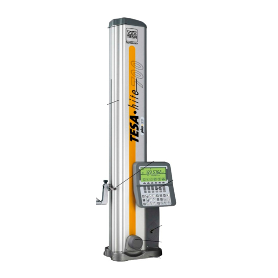
TESA-hite plus M 400 / 700 1 MAIN FEATURES Cap cover 1 Housing 2 Handle 11 Mounting pin 3 Control panel 10 Probe fixing arm 4 Probe 5 Switch for electric pump 9 Rotary power control 8 Guiding and 3-points cast-iron... -
Page 5: Installation
2 INSTALLATION 2.1 Unpacking and setting up The TESA-Hite plus M 400 / 700 is delivered ex factory, packed to protect it from impact and corrosion. Please use the original packing materials for any subsequent transport. IMPORTANT: Your instrument is supplied with a 6V rechargeable battery already inserted. For recharging the battery, see section 12.2. -
Page 6: Starting The Instrument
2.2 Starting the instrument Activate the electric pump using the relevant switch (11) to generate the air-cushion for easy displacement of the TESA-Hite plus M 400 / 700 on the surface plate. Next, start the height gauge by pressing key for more than one second. -
Page 7: Description Of The Components
These lugs form a large surface so that any grooves or other similar irregularities in the surface plate can be comfortably cleared. The lugs 6 (Fig. 1) are designed especially for supporting the TESA-Hite plus M 400 / 700 against a parallel rule or for guiding it along such a rule, for example. - Page 8 TESA-hite plus M 400 / 700 or counterclockwise for approaching the measuring point whether quickly or slowly, probing up and down or performing bore measurement. Operating functions using the rotary power control Usually, these functions are identical to those of the keypad.
- Page 9 TESA-hite plus M 400 / 700 Short rotation (<0,7 s) in the probing direction. Bore measurement A second short rotation of the power control in the same direction permits bore measurement with detection of the culmination point. Turn the power control clockwise to start probing the upper point.
-
Page 10: Power Supply
TESA-hite plus M 400 / 700 3.5 Power supply The TESA-Hite plus M 400 / 700 is powered by a 6V rechargeable battery (N° 00760157). This is recharged using the mains adapter N° 04761054 and the cable EU N° 04761055 or US N°... - Page 11 TESA-hite plus M 400 / 700 Measuring in two coordinate directions. Measuring without inversion of the probing direction Making no allowance for the probe constant Measuring with inversion of the probing direction Making allowance for the probe constant - with no storage of the culmination point...
-
Page 12: Control Panel
TESA-hite plus M 400 / 700 « min » « max »-« min » Measuring in two coordinate directions 4.2 Control panel... -
Page 13: Keyboard
TESA-hite plus M 400 / 700 4.2.1 Keyboard Function keys Press tp switch height gauge on or off. Keep pressing this key ( > 0.6 sec) to get confirmation. Reset the measuring counter to 0. Initialisation of the programme to be saved « Learn ». - Page 14 TESA-hite plus M 400 / 700 Probing down with detection of the highest culmination point. Measure the centre and width of a grove. Measure the centre and diameter of a bore. Measure the centre and diameter of a shaft. Cancel last function or probing operation.
-
Page 15: Display
TESA-hite plus M 400 / 700 Create a « Learn » programme. Executing a programme. Managing programme and data files. Allows the cursor to move up by one position or one field. In measuring mode: Entry in the measurement memory and display the first 4 values with scrolling of the other one by one. - Page 16 TESA-hite plus M 400 / 700 Symbol empty battery Built-in printer (ON) Measured value Date output (ON) Auxiliary measured value Symbols of the function keys...
- Page 17 TESA-hite plus M 400 / 700 Main display Displayed data related to a bore (example) - F1 Prompt for new probe constant. - F2 Prompt for new capture of the relevant reference value (the counter of the measure is not reset to zero).
-
Page 18: Starting Up
TESA-hite plus M 400 / 700 Display format in mode measurement Auxiliary display large format Display the last measured value. Auxiliary display small format Display the last 4 measured values. 4.3 Starting up... - Page 19 TESA-hite plus M 400 / 700 Switching On Press this key (> 0,6 s) to initialise your control panel and load correction values stored in the EEPROM. Firmware V X.XX shows the software version. Searching for the reference mark Move up over a distance of approx.
- Page 20 TESA-hite plus M 400 / 700 Accessing the test menu > Burn in, Moving up and down automatically > Test the internal printer, print all characters > Test the display, show all characters > Test the keyboard > Cancelling all data files >...
- Page 21 TESA-hite plus M 400 / 700 Yes: all data files will deleted along with the programme files. Special case: Special case: communicatio n with EEPROM Accessing the test menu Access measurement mode without correction Possibility : Managing files File transfer...
-
Page 22: Probing Procedure At The Contact Point
TESA-hite plus M 400 / 700 4.4 Probing procedure at the contact point In order to ensure the reliability of the measured values, the following condition must be fulfilled: the probe 5 should be firmly attached to the probe fixing arm 4 which in turn is fixed to the mounting pin 3. - Page 23 TESA-hite plus M 400 / 700 3 Release value capture by means of the rotary power control or by activating the relevant function key. Probe speed: 7,5 or 15 mm/s, selectable in the configuration menu. 4 Constant measuring force is ensured by the friction mechanism as soon as the insert is contacting the relevant point.
-
Page 24: Establishing The Probe Constant For Length Measurements With Inversion Of The Probing Direction
TESA-hite plus M 400 / 700 4.5 Establishing the probe constant for length measurements with inversion of the probing direction Whenever bores, shafts, grooves and the like are measured with inversion of the probing direction, the probe constant has to be taken into account. - Page 25 TESA-hite plus M 400 / 700 Establishing the probe constant for length measurements with inversion of the probe direction Start probe constant acquisition using rotating power control by 1 click for probing the master piece (internal part) pressing For probing the...
- Page 26 TESA-hite plus M 400 / 700 Probe contact 2 (down) Exit constant mode Probe contact 3 Probe contact 3 (up) Exit constant mode Probe contact 4, displayed value after probe contant i iti Probe contact 4 (down). Ready for capturing...
- Page 27 TESA-hite plus M 400 / 700 Probe contact 1 (up) Exit constant mode...
- Page 28 TESA-hite plus M 400 / 700 Position probe insert above the Probe contact 2 upper face of the master piece Probe contact 2 (down) Or rotate the power control by one click Exit constant mode Probe contact 3 Probe contact 3...
- Page 29 TESA-hite plus M 400 / 700 Difference between the four measured values is too high Criteria: Resolution 0,1 µm: Repeatability is checked after probe contact 4 has been <0,5 µm performed. If difference is too high, the last two probe Resolution 1 µm:...
- Page 30 TESA-hite plus M 400 / 700 Difference between the four measured values is too high Criteria: Resolution 0,1 µm: Repeatability is checked after probe contact 6 has been <0,5 µm performed. If difference between the first and the third Resolution 1 µm: couple of measured values is too high, relevant value will <2 µm...
-
Page 31: Programming Retraction Travel
TESA-hite plus M 400 / 700 Assigne New value once number entered 20.0020 New value is registered and remains stored in the memory even after the height gauge has been switched off. Ready for probe constant acquisition 4.6 Programming retraction travel... -
Page 32: Capturing A Reference Value
TESA-hite plus M 400 / 700 New value once entered (example: 10 mm) Ready for capturing reference value with a single probe contact 4.7 Capturing a reference value Measuring without inversion of the probing direction : mode St-1 Capturing reference value St-1 with a single probe contact... - Page 33 TESA-hite plus M 400 / 700 Mode St-1 Display shows one single probe V-shaped signs Or rotate appear according to the power the direction to which control by the carriage moves. one click Number of signs at a speed of 7,5 mm/s = or 15 mm/s = 2.
- Page 34 TESA-hite plus M 400 / 700 Approaching first probing point Mode St-2 Display shows two probes. V-shaped signs Or rotate appear according to the power the direction to control by which the carriage one click moves. Number of signs at...
- Page 35 6 measuring functions available for probing another point. – If the rotary power control is used to move the probe insert, TESA-HITE plus M will repeat the same function at a new location.
-
Page 36: Preset Mode
TESA-hite plus M 400 / 700 4.8 PRESET mode Entering a PRESET value against an indirect reference Input PRESET value PRESET value once entered (example: 35.0066 mm) Ready for capturing indirect reference with a single probe contact... -
Page 37: Measuring Features With Flat Or Cylindrical Surfaces
TESA-hite plus M 400 / 700 4.9 Measuring features with flat or cylindrical surfaces The probes used for contacting flat or cylindrical surfaces are those producing point contacts. Such probes are either ball, barrel or disk shaped (see standard and optional accessories). -
Page 38: Measuring Centre Distances Of Threads
During the probing operations, the probe axis must be, as far as possible, parallel to that of the thread to be inspected. Consequently, TESA-Hite plus M has to be positioned very carefully. The determination of a thread axis using a barrel-shaped contact pin instead of a cone- shaped one is by far more accurate. -
Page 39: Pause And Access To The Configuration Menu
TESA-hite plus M 400 / 700 5 PAUSE AND ACCESS TO THE CONFIGURATION MENU Use this function key to activate the still mode of the instrument and the access to the configuration menu. Once this is done, you may continue measuring based on a new reference C. -
Page 40: Configuration Menu
TESA-hite plus M 400 / 700 5.1 Configuration menu To access this menu, press the F1 key . To exit this menu, press the F6 key Choose your option with then press Enter to confirm . You 1 Unit format... - Page 41 TESA-hite plus M 400 / 700 5.1.2 Language (2) Allows to choose your preferred language. Choose language with Or select then press parameter to confirm. and confirm Langue To cancel all changes and Language: English / Deutsch / Français return to the...
- Page 42 TESA-hite plus M 400 / 700 Speed / Stabilisation Measuring speed: / 15 mm/s to confirm. Quick move: 20 / / 40 mm/s To cancel all Stabilisation: Auto / 0,5s/ 1s / 2s / % changes and Display delay: return to the...
- Page 43 TESA-hite plus M 400 / 700 Choose parameter with Or select then press parameter and confirm Input / Output RS 232 to confirm. Output / Printer SPC / OFF / IN To cancel all Baud Rate : ◄▬►4800 changes and...
- Page 44 TESA-hite plus M 400 / 700 All values captured in this way will be corrected based on the following information: Reference temperature (default value : 20 °C) Height gauge temperature Workpiece temperature α Coefficient of linear expansion of the height gauge (fixed value) α...
- Page 45 TESA-hite plus M 400 / 700 Or select Date and time parameter Date 2007 : 02 : 05 to confirm. and confirm Time : 14 : 22 : 18 To cancel all changes and return to the configuration menu, press 5.1.9 Default parameter (9)
-
Page 46: Measuring Using The Reference C
TESA-hite plus M 400 / 700 Introduce the access code then press to confirm. (Long press) To delete the access code Or select Code d’acces introduce parameter nothing and and confirm Entrez le nouveau code d’acces : press the enter key. - Page 47 TESA-hite plus M 400 / 700 Capture reference value. Displayed value after first probe contact. Displayed value after second probe contact. Calculation of the distance between the last two measured values.
-
Page 48: Measuring Functions
TESA-hite plus M 400 / 700 Displayed value after third probe contact. Quit PAUSE mode and return to previous stage. 6 MEASURING FUNCTIONS 6.1 Measuring grooves Probing procedure... - Page 49 TESA-hite plus M 400 / 700 Position probe insert in the groove pressing both positioning keys or rotating the power control. Probe moves up automatically for first value capture. Single probe symbol appears as first value is being captured. Once retracted,...
-
Page 50: Measuring Bores
TESA-hite plus M 400 / 700 Probing procedure is ended. Probe retraction occurs automatically. Display switches over to normal display. 6.2 Measuring bores Probing procedure Position probe insert into the bore using both positioning keys or the rotary power control. - Page 51 TESA-hite plus M 400 / 700 Probe moves up. Probe symbol appears as soon as probe insert has stabilised after contacting the workpiece feature. Moving the workpiece (or the vertical column) laterally allows automatic detection of the culmination point with a BEEP sound and highlighted probe symbol to warn you.
- Page 52 TESA-hite plus M 400 / 700 Probe moves down. For faster displacement, use the rotary power control. Probe symbol appears as soon as probe insert has stabilised after contacting the workpiece feature. Moving the workpiece (or the vertical column) laterally allows automatic detection of the culmination point with a BEEP sound and highlighted probe symbol to warn you.
-
Page 53: Measuring Shafts
TESA-hite plus M 400 / 700 6.3 Measuring shaft Probing procedure Position probe insert below the diameter to be measured by pressing both positioning keys or rotating the power control. Release the measurement cycle by pressing the relevant function key. - Page 54 TESA-hite plus M 400 / 700 Moving the workpiece (or the vertical column) laterally allows automatic detection of the culmination point with a BEEP sound and highlighted probe symbol to warn you. This point must be probed once (default setting). But, you may choose to travel past this point twice by pressing the ENTER key.
- Page 55 TESA-hite plus M 400 / 700 Probe symbol appears as soon as probe insert has stabilised after contacting the workpiece feature. Moving the workpiece (or the vertical column) laterally allows automatic detection of the culmination point with a BEEP sound and highlighted probe symbol to warn you.
-
Page 56: Calculating Median
TESA-hite plus M 400 / 700 6.4 Calculating median Provided the value numbering option is not selected, you can access this function any time by pressing . The median is usually calculated from the measured values obtained for both part features that were last displayed. - Page 57 TESA-hite plus M 400 / 700 Skip value storage when carrying out the measurement directly. Registring median value as dimension M6 = (M05:M04) Acknowledged median value as dimension M6. Activation of the median function Calculation of the mean value of the two part features you’ve...
- Page 58 TESA-hite plus M 400 / 700 Choose desired values Skip one measured value upwards using the arrow keys or enter Skip one measured value downwards value number through the keyboard. Skip one page (4 values) upwards Skip one page (4 values) downwards...
-
Page 59: Calculating Distance
TESA-hite plus M 400 / 700 Confirm displayed value M2 for the calculation of the median as M7 = M5:M2 6.5 Calculating distance Providing the option Value Numbering was not selected earlier, you can access this function any time by pressing . - Page 60 TESA-hite plus M 400 / 700 Calculation of the distance between both part features you’ve last measured. At this point, the programme gives you the choice between three possibilities: Store distance value as M06 dimension by pressing function key F6...
- Page 61 TESA-hite plus M 400 / 700 Auxiliary display shows the last four values from the table. Higher value is highlighted. Choose desired values using the Skip one measured value upwards arrow keys or enter value Skip one measured value downwards number through the keyboard.
- Page 62 TESA-hite plus M 400 / 700 Choose displayed value M2 as second parameter for calculating distance value. Confirm displayed value M2 for the calculation of distance value M7 = M5-M2...
-
Page 63: Measuring A Diameter Or A Width
TESA-hite plus M 400 / 700 6.6 Measuring a diameter or a width Standard display after each probe contact. The main display shows temporally the difference between the 2 of the measured element and save it as a dimension. Main display will... -
Page 64: Additional Measuring Functions
TESA-hite plus M 400 / 700 7 ADDITIONAL MEASURING FUNCTIONS You may access in this menu by simply activating the function key : Capturing parallelism errors : Measuring angles : Measuring perpendicularity and straightness deviations : 2D measurement : Exit of the additional functions menu... - Page 65 TESA-hite plus M 400 / 700 7.1 Capturing parallelism errors You may access the menu MAX/MIN from any position within part programs by simply activating the function key and then To exit this menu and return to the reference mode you’ve previously...
- Page 66 TESA-hite plus M 400 / 700 Display continuously shows the measured value against active reference. V-sign indicates probe moving direction. Rotary power control may be used for approaching relevant probing Or rotate point. power control Zero value appears once probe insert has stabilised.
- Page 67 TESA-hite plus M 400 / 700 Activation the PAUSE After PAUSE has been prompted, display shows both Min and Max values. Value acquisition is deferred. Measured value reappears. V-sign indicates probe moving direction. Measured value stops fluctuating. Display shows both Max and Min values.
- Page 68 TESA-hite plus M 400 / 700 Registring measured value If you’ve activated value numbering in configuration menu, value shown on main display is added in the register (M = ?). Prompting for value rotation on main display (∆, Max and Min values).
- Page 69 TESA-hite plus M 400 / 700 Exiting the menu of parallelism measurement Return to main display All subsequent measurements will be taken based on the reference value you’ve activated before accessing menu Measuring parallelism errors. Prompting for parallelism measurement in ABS mode...
- Page 70 TESA-hite plus M 400 / 700 Once probe insert has stabilised, display shows absolute value measured against active reference value. Measured value stops fluctuating. Display shows the deviation along with both absolute Max and Min values. M= ? adds or rotating...
- Page 71 TESA-hite plus M 400 / 700 Display shows value measured as probe is being displaced. V-sign indicates probe moving direction. Rotary power control may be used for or rotating approaching the power relevant point. control Once probe insert has stabilised, display shows PRESET value.
-
Page 72: Measuring Angles
TESA-hite plus M 400 / 700 7.2 Measuring angles To access into the angle measuring mode of any inclined surface to the reference surface, simply activate the function keys and then Possible condition before accessing the angles measuring mode (St-2 with value numbering) - Page 73 TESA-hite plus M 400 / 700 Measuring angle of any inclined surface to reference surface Angle calculation based on two probing points. General Probe contacts of any type are allowed in either modes St-1 or St-2. Probe point P1 Probe point P2...
- Page 74 TESA-hite plus M 400 / 700 Probing gauge block Probe first point on the gauge block. Probe second point on the gauge block. Relevant angle = arc tg (P2-P1)/X is being calculated. Display shows calculated value in selected unit. Perform new...
- Page 75 TESA-hite plus M 400 / 700 Angle measurement between the axis passing by two centres and the reference plan Probe bore 1 in the direction of the Y axis. Probe bore 2 in the direction of the Y axis. Turn the part 90° in the clockwise direction.
- Page 76 TESA-hite plus M 400 / 700 Changing units of measurement Temporary conversion into degrees. Temporary conversion into radian. Press F4 to replace radian by the unit you’ve previously selected by pressing F3. Entering gauge block dimension Prompt for value input once you’ve probed point P2.
- Page 77 TESA-hite plus M 400 / 700 Entering Enter desired X value = value. 52.8762 through keyboard Press to confirm Angle = arc tg (P2-P1)/X is calculated. Display shows calculated value in the unit previously selected in configuration Registering gauge block height...
- Page 78 00760222) and connect the output on the interface (N° 04760070), itself connected on the RS connector of the TESA-Hite. It is recommended to use a GT21 inductive probe connected to a TT20. The bidirectional cable (N° 04761049) has to be used. The measuring time is 70ms that means 14 measurements per second.
-
Page 79: Measuring Perpendicularity And Straightness Deviations
TESA-hite plus M 400 / 700 Entering a PRESET value in the Z axis Setting the counter to zero in both X and Z axes Entering the measuring range in the Z axis Entering the measuring range in the X axis (based on the graph scale) - Page 80 TESA-hite plus M 400 / 700 There are several ways to start up your probing operations. Activating this key or rotating the power control clockwise by one click allows you to start probing up. Activating this key or rotating the power control counter clockwise by one click allows you to start probing down.
- Page 81 TESA-hite plus M 400 / 700 Désactivation du mode PAUSE Start data acquisition back again. Affichage général après acquisition des valeurs Full display shows measurement results The main display shows the current probe position. = 0.1560 = 0° 04’41’’ Or rotate...
- Page 82 TESA-hite plus M 400 / 700...
- Page 83 TESA-hite plus M 400 / 700 Prompting for perpendicularity error Main display : Shows perpendicularity error (Max-Min). Auxiliary display: Shows measuring range in Z axis. At this point, you may decide to press either of the following keys: to save measured value in the register (provided value numbering was initially enabled in the configuration menu and the reference St-1/2 has been captured).
- Page 84 TESA-hite plus M 400 / 700 Prompting for highest value Main display: Shows highest value (Max) Auxiliary display: Shows the position of this value in the Z axis From this stage, you may ask for all operations described under « Prompting for perpendicularity error »...
- Page 85 TESA-hite plus M 400 / 700 Save lowest value in the register. Affichage de l’angle de rectitude The main display shows the measured value. At this point, you may press either of the following keys: to change temporarily angle unit into decimal degree or radian.
- Page 86 TESA-hite plus M 400 / 700 Return to measurement ⊥ results of previously displayed. = 0.1560 = 0° 04’41’’ Z= 115.0065 = 0.0259 Prompting for straightness error Main display shows measured straightness error. From this stage, you may ask for all operations described under « Prompting for perpendicularity error »...
- Page 87 TESA-hite plus M 400 / 700 Prompting for graph curve of measured values Auxiliary display shows graph curve along with Z range. The main display shows the measuring Z range From this point, you may press either of the following keys: ⊥...
- Page 88 TESA-hite plus M 400 / 700 Validate PRESET value in Z axis. The position in the Z axis of the PRESET value can be initialized by using the key. Setting counter of both Z and X axes to zero The 0 position is...
- Page 89 TESA-hite plus M 400 / 700 Measuring range in X axis Input graph scale values related to the X range through the keyboard. Both values may be lying within ± 0,0500 and ± 50.0000 mm Confirm by pressing or skip validation and press F5 to quit.
-
Page 90: Measurement
TESA-hite plus M 400 / 700 7.4 2D measurement To access the 2D measuring mode from the standard mode, the following conditions must first be met: Probe constant has to been established prior to access in the 2D mode. Capture of the reference before or at least at the time you were accessing the 2D mode. - Page 91 TESA-hite plus M 400 / 700 Entering in measuring mode 2D M values saved in the register may either be retained or erased if automatic numbering has been selected. In this example, Yes prompts for next value M1. No prompts for...
- Page 92 TESA-hite plus M 400 / 700 7.4.1 Measuring in coordinate direction Y Measuring in Y axis Probe bore 1 with detection of the culmination point. Display shows measured value H1 (Y) Confirm next proposed value or input a new number.
- Page 93 TESA-hite plus M 400 / 700 Input desired number to Hy. Confirm number of next bore to be probed. Probe bore 3 with detection of the culmination point. Enter number of next bore (6) to be probed with detection of the culmination point.
- Page 94 TESA-hite plus M 400 / 700 7.4.2 Measuring in coordinate direction X Prompting for workpiece rotation Confirm default value (angle to 90°) or displayed value if you’ve previously pressed F5. You may also change angle unit or input a new angle value.
- Page 95 TESA-hite plus M 400 / 700 Measuring in X axis Probe bore 1 with detection of the culmination point. Bore that comes next in the table is proposed in the order of the probe contacts made in X axis Display shows...
- Page 96 TESA-hite plus M 400 / 700 Probing bore 7 additionally Rotate X axis to Y axis. Display shows angle value with reverse sign. 90’ Confirm rotation through axis Y. Probe bore 7 without detection of the culmination point in Y axis.
- Page 97 TESA-hite plus M 400 / 700 Repeat workpiece rotation through X axis, then confirm. Display shows height value which was last captured in this axis Probe bore 7 in X axis with detection of the culmination point. Display shows measured value H 7(X) End Measuring in both coordinate directions X and Y.
- Page 98 TESA-hite plus M 400 / 700 7.4.3 Checking 2D measurements Prompting for InSPECt to view Hy and Hx values Use the arrow keys to have measured values displayed or enter desired number directly through the keyboard. Next, press Enter to confirm.
- Page 99 TESA-hite plus M 400 / 700 Keep pressing this key, to print all values of the H elements. Prompting for calculation of a regression circle Number of displayed Px matches that of measured H (max. 12 per page). Number of...
- Page 100 TESA-hite plus M 400 / 700 Confirm and return to InsPECT mode. Display shows coordinate values along with the measured diameter and the difference between both max and min values. At this point, you may either return to the probing mode by pressing...
-
Page 101: Performing 2D Analyses
TESA-hite plus M 400 / 700 7.5 Performing 2D analysis A 2D analysis allows you to execute various operations such as levelling and selecting the coordinate system or the numbered values M you want to print out. First, you need to determine the origin of the coordinate system. - Page 102 TESA-hite plus M 400 / 700 Display shows the feature you’ve selected in the new coordinate system. (H values are converted into d values). Available keys and functions To viw the other part features using the arrow keys Display the next feature...
- Page 103 TESA-hite plus M 400 / 700 7.5.2 Rotation of displayed value through the main system Shift Y value to main display. Shift mean diameter to main display. Shift measured diameter in Y axis to main display. Shift measured diameter in X axis to main display.
- Page 104 TESA-hite plus M 400 / 700 7.5.3 Aligning the coordinate system to the bore axis This function is prompted for once the origin point has been determined Enter number of the relevant bore to proceed in X axis. If you want to...
- Page 105 TESA-hite plus M 400 / 700 Confirm pressing and the display shows feature you’ve selected in the coordinate system. Alignement de l’axe Y Enter desired number. Follow the same procedure as for X axis.
- Page 106 TESA-hite plus M 400 / 700 7.5.4 Changing measured values into polar coordinates Prompting for changing coordinates Display shows the feature you’ve selected in the new polar coordinate system. Changing into cartesian coordinates...
- Page 107 TESA-hite plus M 400 / 700 7.5.5 Registering a measured dimension Use the arrow keys together with to choose the value you want to save in the constant table M – i.e. the distance between both part features 1 and 3 in the example shown below.
- Page 108 TESA-hite plus M 400 / 700 Example : prompting part feature with number Display shows prompted feature 6. From the previous step 7.5.6 Auxiliary geometric functions Have part feature 6 being displayed in polar coordinates before going on.
- Page 109 TESA-hite plus M 400 / 700 Prompt for auxiliary geometric functions. Available functions: Translation of coordinate system to another part feature Rotation of coordinate axes through a given angle Definition of the coordinates of a fictitious point Calculation of the regressions circle...
- Page 110 TESA-hite plus M 400 / 700 7.5.6.1 Translating the coordinate system from the reference axis to new axis Prompt for auxiliary geometric functions. Prompt for translation of coordinate system.
- Page 111 TESA-hite plus M 400 / 700 Enter number of relevant part feature. Confirm translation of origin point and return to analysis (main menu). Display shows origin point in the new coordinate system. 7.5.6.2 Rotating the coordinate system through its origin point...
- Page 112 TESA-hite plus M 400 / 700 Prompt for rotation of coordinate system. Entering Input rotation 36.22 via angle of coordinate keyboard system. Confirm input value. Display shows part feature you’ve previously selected in the new coordinate system.
- Page 113 TESA-hite plus M 400 / 700 7.5.6.3 Creating a fictitious point Prompt for auxiliary geometric functions. Prompt for polar coordinate system. Enter R value, Entering angle value and data feature number through through the keyboard. keyboard Use the arrow keys to move from a field to another.
- Page 114 TESA-hite plus M 400 / 700 Prompt for cartesian coordinate system. Entering Enter both X and data Y values along through with relevant number. keyboard Use the arrow keys to move from a field to another. Display shows both values...
- Page 115 TESA-hite plus M 400 / 700 7.5.6.4 Calculating the regression circle Prompt for auxiliary geometric functions. Number of displayed Px matches that of measured H (max. 12 per page). Number of features used for calculating the regression circle may be within 3 and 64.
- Page 116 TESA-hite plus M 400 / 700 Enter each number. You’ll get a warning message if desired feature has been used or if it was not probed. Use arrow key to move the 10 + cursor to dr= for entering relevant number and validate with Enter.
- Page 117 TESA-hite plus M 400 / 700 7.5.6.5 Calculating the angle between 3 geometric elements Prompt for relevant function. This function may also be prompted from 2D analysis. Enter requested Entering data. data through Special case: Press F2 to enter keyboard...
- Page 118 TESA-hite plus M 400 / 700 7.5.6.6 Calculating the distance between 2 points In cartesian coordinate system : Prompt for relevant function. This function can also be prompted from 2D analysis Entering Enter requested data data. through If your entry...
- Page 119 TESA-hite plus M 400 / 700 In polar coordinate system : Prompt for relevant function. This function can also be prompted from 2D analysis Entering Enter requested data data. through If your entry keyboard needs to be complemented or one of the...
-
Page 120: Saving, Executing A Part Programme And Managing Files
TESA-hite plus M 400 / 700 8 SAVING, EXÉCUTING ADPART PROGRAMME AND MANAGING FILES To access this mode press the key : Creating a part programme « Learn » Possibility of introducing only numbers as a name of a part... - Page 121 TESA-hite plus M 400 / 700 8.1 Creating a part programme « Learn » To create a part programme by learning « Learn », you need just measure as usual, then press the keys as detailed in the example that follows.
- Page 122 TESA-hite plus M 400 / 700 Display tells you that the file is existing while prompting you to answer accordingly. If the answer is NO, you may enter a new file name. Save your file «Learn programme » and return to the measuring mode.
- Page 123 TESA-hite plus M 400 / 700 To create a 2D part programme, proceed in the same way. You may also access this mode after you’ve carry out a number of 1D measurements. Procedure Capture constant value prior to reference value St2 Set counter to zero, if necessary.
- Page 124 TESA-hite plus M 400 / 700 8.2 Executing a part programme The configuration menu provides a number of parameters which may need to be specifically set for each part programme. The settings that need be made for running this part programme are described as follows: Probing speed: 7,5 / 15 mm/s Fast displacement: 20 / 30 / 40 mm/s.
- Page 125 TESA-hite plus M 400 / 700 8.2.1 Programme simple 1D Follow this procedure to execute a simple 1D part programme Accessing the Execution mode Choose desired meaurement programme Select desired file using the arrow keys Press F1 to return St-1/2...
- Page 126 TESA-hite plus M 400 / 700 Display shows next part feature to be probed. Condition: M1: Auto/OFF, M1: Pos/OFF (dependin g on Position probe previous manually. setting) or using the rotary power control Probe relevant bore. or using the rotary...
- Page 127 TESA-hite plus M 400 / 700 Probe is Automatic automatically positioning positioned to the part feature M3. Positioning options : - at the centre of a bore or a groove -3 mm away from the surface to be probed once for...
- Page 128 TESA-hite plus M 400 / 700 Automatic Probe is positioning automatically as set positioned to the next part feature (M4).. Display shows Numbered numbered value value M4 has been captured Response and waiting times are those previously entered in the configuration mode.
- Page 129 TESA-hite plus M 400 / 700 Once each workpiece has been measured, the following options are available: To save the measured values in the relevant data file, close data file, return to first step for selecting another part programme or exit.
- Page 130 TESA-hite plus M 400 / 700 8.2.2 Programme with angle, perpendicularity and 2D measurements The way some specific measurements are carried out is described hereafter: Generaring the capture of a new reference B Activating Display shows numbered value according to set...
- Page 131 TESA-hite plus M 400 / 700 Carrying on with parallelism measurement Activating Access the measuring mode. according to set Programme is parameter waiting until first s in the probe contact is edition started up. mode. Display shows floating value. V-sign indicates...
- Page 132 TESA-hite plus M 400 / 700 Main display shows numbered value M8. Auxiliary display shows next part feature to be probed: M9 Maximum Remark : If MAX and MIN are wished in absolute, the Or using absolute mode the rotary...
- Page 133 TESA-hite plus M 400 / 700 First probe contact Or using the rotary power control...
- Page 134 TESA-hite plus M 400 / 700 Second probe contact Or using the rotary power control At this point, you may go ahead according to the procedure you’ve followed when creating the part programme, i.e.: - Measuring the gauge block(as described in chapter 7.2) - Entering manually the gauge value has (as described in chapter 7.2)
- Page 135 TESA-hite plus M 400 / 700 Numbered value that comes next will be displayed according to selected part programme. In this example, display shows Z value along with the value obtained from the probe. The probe may also be positioned by rotating the power control.
- Page 136 TESA-hite plus M 400 / 700 Release pause and continue the measurement...
- Page 137 TESA-hite plus M 400 / 700 Display shows the curve of the form error as measured Only, if the curve has been acceded during de creation of the Or using Learn the rotary programme. power control Display shows numbered value...
- Page 138 TESA-hite plus M 400 / 700 Activating Display shows angle value M10 according to set parameter s in the edition mode. Activating Display shows straightness according value M11 to set parameter s in the edition mode. Carrying on with 2D measurement...
- Page 139 TESA-hite plus M 400 / 700 Displaying positioning Display shows along with probe position related for value capture probe (H1). contact This sequence may be interrupted using the rotary power control. Displaying positioning Displayed value along with once captured related...
- Page 140 TESA-hite plus M 400 / 700 Displaying positioning Displayed value along with related probe contact This sequence may be interrupted using the rotary power control. Proceed as in 2D mode for entering angle value. Value last input replaces the previous one.
- Page 141 TESA-hite plus M 400 / 700 Display shows numbered value Response time is the one previously entered in configuration mode. Activating Display shows numbered value according to set parameter Response time s in the is the one edition previously mode.
-
Page 142: Managing Files Menu
TESA-hite plus M 400 / 700 8.3 Managing files menu This mode can be accessed from the measuring mode. Prompt for managing files Make your selection using the arrow keys. ON/OFF key cannot be activated when managing or editing files. - Page 143 TESA-hite plus M 400 / 700 8.3.1 Restoring a measurement programme Prompt for managing files Make your selection using the arrow keys. ON/OFF key cannot be activated when managing or editing files. Cursor shows programme file you’ve last created. Confirm both displayed file and data.
- Page 144 TESA-hite plus M 400 / 700 8.3.2 Editing a measurement programme Prompt for managing files Make your selection using the arrow keys. ON/OFF key cannot be activated when managing or editing files. Cursor shows programme file you’ve last created. Edit chosen tolerance and printing options.
- Page 145 TESA-hite plus M 400 / 700 Displayed constant value which may needs to be captured as the programme is started up. If not, jump to the next step. Capture reference value. You may also input a preset value or enter desired retraction travel.
- Page 146 TESA-hite plus M 400 / 700 Automatic prompting of the dimension as soon as the response time of display is over. OFF: In the Execution mode, press F6 to have this done. Automatic positioning of the probe. The relevant value will be captured automatically as soon as the given response time is over.
- Page 147 TESA-hite plus M 400 / 700 Direct access to a dimension Prompt the listed dimensions Select desired dimension using the arrow keys or enter relevant number through the keyboard. Confirm by pressing Inserting a dimension First choose the programme step...
- Page 148 TESA-hite plus M 400 / 700 Input tolerances. Display shows dimension. Inserting the calculation of the bore diameter To have this done, the function you’ve previously selected must include a dual probe contact. Display shows dimension M03 (M02 before inserting).
- Page 149 TESA-hite plus M 400 / 700 Display shows dimension M04. Tolerances may be changed along with both UCL/LCL control limits according to the configuration of this part programme. Display shows dimension M05. Tolerances may be changed along with both UCL/LCL control...
- Page 150 TESA-hite plus M 400 / 700 Display shows the distance M05. Tolerances may be changed along with both UCL/LCL control limits according to the configuration of this part programme. Save your file before exiting the Edit mode. You may create...
- Page 151 TESA-hite plus M 400 / 700 8.3.3 Cancelling a measurement programme Prompt for managing files Select desired programme using the arrow keys. ON/OFF key cannot be activated when managing or editing files. Cursor shows programme file you’ve last created. Confirm your selection by answering Yes.
- Page 152 TESA-hite plus M 400 / 700 8.3.4 Managing measurement files Prompt for managing files Make your selection using the arrow keys. ON/OFF key cannot be activated when managing or editing files. Cursor shows programme file you’ve last created. Prompt for...
- Page 153 TESA-hite plus M 400 / 700 8.3.5 Statistics menu This menu can be directly called from the managing data file menu. Access from the managing files menu Activate the data files Select desired data file using the arrow keys, then activate the statistic menu.
- Page 154 TESA-hite plus M 400 / 700 Use the arrows key to select desired dimension or enter number of desired Palp. Bas 205.0232 dimension Palp. Bas 160.0342 through the Palp. Bas 115.0065 keyboard. Alésage diamètre 84.9040 Prompting for histogram Displayed data...
- Page 155 TESA-hite plus M 400 / 700 Prompting for Xbar card Displayed measuring process for M1. X scale always shows the last 25 samples of n workpieces. Samples that are not within control limits are either marked with the arrow key ↑ or with ↓...
- Page 156 TESA-hite plus M 400 / 700 Prompting for global statistics S t a t i s t i q u e s G l o b a l e s Pi e ce To ta l Bo n R e b u t 1 0 0 % 7 0 .
-
Page 157: Description Of The Rs 232 Interface
TESA-hite plus M 400 / 700 9 DESCRIPTION OF THE RS 232 INTERFACE To link the TESA-Hite plus M 400 / 700 to the Printer SPC or a PC, use the connecting cable 04761052. Data rate 4800 bauds Data bits... -
Page 158: Printing Formats
TESA-hite plus M 400 / 700 10 PRINTING FORMATS 10.1 Internal printer Date: 25/09/2007 Time: 11:01:36 N° Data Type of measurement Mode St1/2 ° 6.35 Master piece ↓ 0.0000 Ref A Probing down 22.8 °C Temperature of the column ↓... - Page 159 TESA-hite plus M 400 / 700 Regression circle /Inspect Type of measurement 60.8692 (<->) Regression circle 60.8694 (<->)> Regression diameter Max 60.8690 (<->)< Regression diameter Min 82.0835 Regression centre 69.1040 Regression centre 60.8692 (<->) Regression diameter δ(<->) Delta regression 0.0004...
- Page 160 TESA-hite plus M 400 / 700 Analyse cartesian fictive point 25.0000 >o< Fictive point 25.0000 >o< Fictive point Analyse polar fictive point 35.3553 >o< Fictive point 45°00’00" DM S >o< Fictive point Analyse cartesian distance δ1 37.0028 Distance C3-1 δX -27.0562...
- Page 161 TESA-hite plus M 400 / 700 10.2 RS 232 output With the option Printer SPC the TESA-Hite plus M 400 / 700 send not only the measuring value on the RS port, but also a description of it. Printout in measuring mode :...
- Page 162 TESA-hite plus M 400 / 700 Numerical statistic : Histogram : Short press = File name: 000222.01 selected dimension : Date: 25/09/2007 Time: 11:20:07 Start Date : 25/09/2007 Time: 11:03:22 Statistics End Date : 25/09/2007 Time: 11:13:33 Probe down M 1...
- Page 163 TESA-hite plus M 400 / 700 Printout of the parts : Global statistics : Short press : Short press : Printout of the selected part File name : 000222.01 File name: 000222.01 Date: 25/09/2007 Time: 11:53:30 Date: 25/09/2007 Time: 11:52:30...
- Page 164 Start the software bye executing the file Micro-Hite Connect.exe Change PC directory : Chose the directory into the files should be copied. Change COM port : Choose the COM on which the TESA-HITE plus M is connected. Refresh : Activate this button to up-date the file’s list.
- Page 165 The files have been copied and are visible in the PC directory. Proceed on the same way to copy files from the PC into the TESA-Hite plus M, select the files in the PC directory and activate the button Copy to Micro-Hite.
- Page 166 TESA-hite plus M 400 / 700 11.1 Data file format The format of the results file created on the PC is the following: Number of measured value, "Description", Value, Nominal, Upper Tol., Lower Tol., Deviation (Value – Nominal), Start Date: 2007/09/25...
-
Page 167: Maintenance
Fully recharging the battery pack with the mains adaptor N° 04761054 requires about 8 hours. The TESA-Hite plus M 400 / 700 can then be used for about 60 hours. If the battery charge is not sufficient (under 5,8 V), the battery symbol appears on the display. The operator can continue with the measurements for about 15 minutes. -
Page 168: Delivery Programme
TESA-hite plus M 400 / 700 For charging batteries, use only the original adaptor N° 04761054 and proceed as follows: – Connect mains adaptor to the socket located on the back of the TESA-Hite plus M 400 / 700. – Connect adaptor to the mains 110 to 240 Vac / 50 to 60 Hz with connecting cable supplied. - Page 169 TESA-hite plus M 400 / 700 13.1 Optional accessories All insert holder and measuring insert from MICRO-HITE can be used with the TESA-Hite plus M. Measuring insert Measuring insert With tungsten carbide ball tip, Ø 10 mm. With tungsten carbide ball tip, Ø 3 N°...
- Page 170 TESA-hite plus M 400 / 700 N° 00760096* Ø 1 mm N° 01860201* Ø 2 mm N° 01860202* Ø 3 mm N° 01860203* N° 01860307* Measuring insert Measuring insert With a Ø 10 mm tungsten carbide cylindrical face With both a flat and spherical tungsten carbide and 12 mm length.
- Page 171 TESA-hite plus M 400 / 700 - Ø 1 mm N° 00760228 - Ø 2 mm N° 00760229 - Ø 3 mm N° 00760230 Holder for GT probes or dial test indicator N° 00760222 Probe insert set N° 00760175 Composition of the set: Supplied in a suited plastic case.
-
Page 172: Technical Data
TESA-hite plus M 400 / 700 00760180 00760181 00760182 00760183 00760184/5 TESA PRINTER SPC N° 06430000 Supplied with: 1 Roll heat sensitive paper N° 04765013 1 Mains adaptor, 100 to 240 Vac / 50 to 60 Hz, 6,6 Vdc / 750 mA N°... -
Page 173: Warranty
TESA-hite plus M 400 / 700 Guidance across the reference surface through mechanical contact Material measure incremental glass scale with reference point Capturing opto-electronic Coefficient of expansion 12±1.5 10 Measuring head Guiding on ball-bearings Head displacement motorised Maximum perm. displacement speed 600 mm/s (manual) –... - Page 174 TESA-hite plus M 400 / 700 We declare under our sole responsibility that this product is in conformity with all technical data as specified in our sales literature (instruction manual, leaflet, general catalogue). In addition, we certify that the measuring equipment used to check this product refers to national reference standards.
- Page 175 TESA-hite plus M 400 / 700 NOTES...
Need help?
Do you have a question about the TESA-hite plus M 400 and is the answer not in the manual?
Questions and answers