Advertisement
Quick Links
AMD Socket A
Declaration of Conformity
VIA KT600 + VT8237
ATX Motherboard
According to 47 CFR, Parts 2 and 15 of the FCC Rules
The following designated product:
User's Guide
EQUIPMENT: MAINBOARD
is a Class B digital device that complies with 47 CFR Parts 2 and 15 of the FCC
Rules. Operation is subject to the following two conditions:
1. This device may not cause harmful interference.
2. This device must accept any interference received, including interference that may
cause undesired operation.
This declaration is given to the manufacturer:
CHAINTECH-EXCEL COMPUTER INC.
4427 Enterprise St. Fremont, CA 94538, U.S.A.
http://www.chaintechusa.com
Chaintech President: Simon Ho
Signature:
Advertisement

Related Manuals for CHAINTECH SKT600


Summary of Contents for CHAINTECH SKT600
- Page 1 1. This device may not cause harmful interference. 2. This device must accept any interference received, including interference that may cause undesired operation. This declaration is given to the manufacturer: CHAINTECH-EXCEL COMPUTER INC. 4427 Enterprise St. Fremont, CA 94538, U.S.A. http://www.chaintechusa.com Chaintech President: Simon Ho Signature:...
- Page 2 Federal Communications Commission Statement TABLE OF CONTENTS This device complies with FCC Rules Part 15. Operation is subject to the following two conditions: * This device may not cause harmful interference. Introduction ..............1 Chapter 1 * This device must accept any interference received, including interference that may cause undesired operation. 1-1 Product Specifications....................
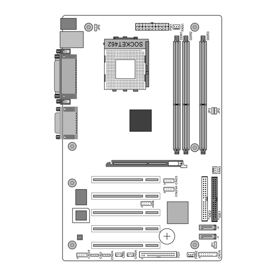
- Page 3 Chapter 1 Chapter 1 1-3 Motherboard Layout Introduction Chapter 1 1-1 Product Specifications Processor Supports AMD Socket A Athlon XP/Duron CPU Supports system clock at 200/266/333/400 MHz Chipset VIA KT600 + VT8237 Main Memory Supports three 184 pin DDR DIMMs up to 3GB Supports PC 2100/2700/3200 DDR SDRAM modules Expansion Slots One Universal AGP slot for both 4X/8X AGP...
- Page 4 Chapter 2 Chapter 2 2-3 Main Memory Configuration Hardware Setup Chapter 2 The DDR SDRAM memory system consists three banks, each bank supports up to 1GB If your motherboard has already been installed in your computer you may still need to of memory.
- Page 5 Chapter 2 Chapter 2 Power Button Operation diagram. PW1 (ATX Power Supply Connector) 2. P-LED (Power LED Connector) The power cord leading from the system's power supply to the The power indicator LED shows the system's power status. It is important to pay external power source must be the very last part connected attention to the correct cables and pin orientation (i.e.
- Page 6 Chapter 2 Chapter 2 JP6 (Enable/Disable USB 0/1 Device Wake-Up Jumper) CN23/23A/23B (Front USB Connector for USB 2/3, 4/5 and 6/7) USB Port 2/3 CN23, USB Port 4/5 CN23A, An USB keyboard hot key or an USB mouse Definition USB Port 6/7 CN23B click can activate this board.
- Page 7 Chapter 3 Chapter 3 3-2 Advanced BIOS Features BIOS Setup Program Chapter 3 By choosing the Advanced BIOS Features option from the CMOS Setup Utility menu Phoenix-Award BIOS ROM has a built-in setup program that allows users to modify the (Figure 3-1), the screen below is displayed.
- Page 8 Chapter 3 Chapter 3 keyboard controller. Available options are [Fast] and [Normal]. Video BIOS Shadow Typematic Rate Setting Enabling this function will allow the BIOS setting of the VGA card to be saved in RAM When enabled, you can set the following two-typematic control items. When disabled, for better performances.
- Page 9 Chapter 3 Chapter 3 3. AGP Driving Control Video RAM Cacheable The [Manual] setting allows you to manually select the AGP driving value. However, it Enabling this function will allows caching of the video RAM, resulting in better system is recommended that you keep the default setting [Auto] to allow the system to performance.
- Page 10 Chapter 3 Chapter 3 4. Primary/Secondary Master/Slave UDMA Super IO Device Ultra DMA implementation is possible only if your IDE device supports it and your This section provides information on setting Super I/O device. Press [Enter] to enter the operating environment contains a DMA driver. If both your hard drive and software sub-menu, which contains the following items for advanced control: support Ultra DMA, select [Auto] to enable BIOS support.
- Page 11 Chapter 3 Chapter 3 Power Management Option Ac Loss Auto Restart Power management allows the computer to save electricity when it is not in use by Available options: [Auto], [On], [Off]. Please leave the default setting [Off] for a stable entering increasingly deep power saving modes.
- Page 12 Chapter 3 Chapter 3 12. IRQs Activity Monitoring Linear Spread Range Please leave the default setting [1] for a stable system operation. This feature allows you to monitor a list of IRQ, Interrupt ReQuests. When an I/O device wants to gain the attention of the operating system, it signals this by causing an CPU Clock IRQ to occur.
- Page 13 Chapter 4 Note DRIVER Setup Chapter 4 NOTE Insert the support CD that come with your motherboard into your CD-ROM driver or double-click the CD drive icon in [My computer] to open the setup screen. 4-1 VIA Service Pack Setup 1.
- Page 14 How To Contact CHAINTECH How To Contact CHAINTECH Please do not hesitate to contact us if you have any problem about our products. Any opinion will be appreciated. For Asia, Africa, Australia and Pacific For Europe: Island: CHAINTECH EUROPE B.V.
Need help?
Do you have a question about the SKT600 and is the answer not in the manual?
Questions and answers