Advertisement
Quick Links
Instruction Manual
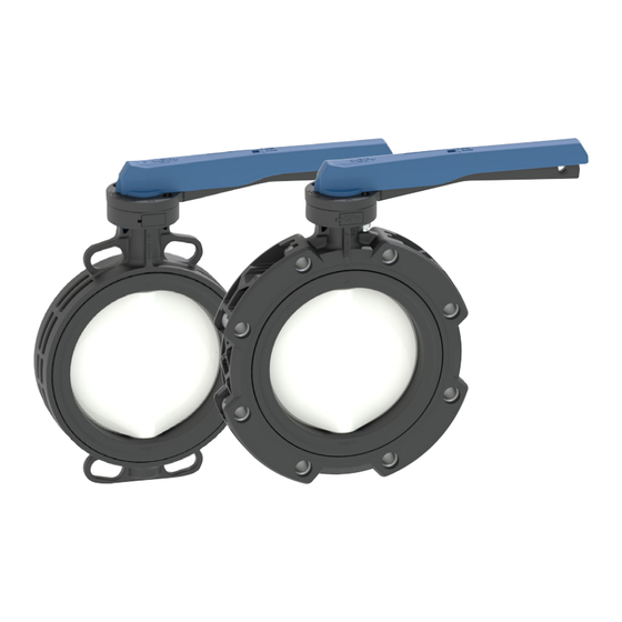
Butterfly Valve Type 565,
manually operated
700278128 / MA_00040 / 06 (08.2024)
© Georg Fischer Rohrleitungssysteme AG
CH-8201 Schaffhausen/Schweiz
Phone +41 52 631 11 11/ info.ps@georgfischer.com / www.gfps.com
1. Safety instructions
1.1 Observe instruction manual
The instruction manual is part of the product and an important component of the safety
concept.
► Read, understand and observe the instruction manual.
► Always keep the instruction manual with the product.
► Pass the instruction manual to subsequent users of the product.
1.2 Abbreviations
DN
Nominal diameter
PN
Nominal pressure
1.3 Safety Instructions and Warnings
Warnings that warn the user of death, injuries or material damage are used in this
instruction manual. Always read and observe these warnings!
WARNING!
Possible danger! Non-observance may result in major injuries.
CAUTION!
Dangerous situation! Non-observance may result in minor injuries.
NOTICE!
Dangerous situation! Non-observance may result in material losses.
1.4 Further symbols and labels
►
Call for action
1.
Call for action in a certain order
1.5 Safety and Responsibility
The safety instructions for the valves are usually the same as for the piping system they
are installed in.
► Products and equipment shall only be put into operation and used by persons who
have the required training, knowledge or experience.
► Make sure that the piping system has been installed professionally and serviced
regularly.
► Never use a damaged or defective product. Immediately sort out damaged or defective
products.
1.6 Transport and Storage
► Transport and/or store product in unopened original packaging.
► Protect product from dust, dirt, dampness as well as thermal and UV radiation.
► Make sure that the product has not been damaged either by mechanical or thermal
influences.
2. Design and definition
2.1 Intended use
The Type 565 Butterfly Valve is designed exclusively to block, pass through or regulate
the flow of approved water-based media in a piping system within the specified pressure
and temperature limits as a butterfly valve. For media other than water-based media
(aggressive, degreasing, containing solids or sticking media, etc.), please consult the
local representative of GF Piping Systems. The maximum limit of operation is 25 years.
2.2 Design
1
Lever
1
2
Spring
3
Grid lever
2
3
4
Screw
5
Index plate
4
6
Washer
7
Nut
5
8
8
Shaft lock
9
O-Ring
11b
12
9
11a
10
Shaft
6
13
14
7
11a
Wafer-style housing
11b
Lug-style housing
12
Cap
10
13
Seat liner
14
Disc
15
Threaded inserts
15
2.3 Operating torque
Operating torques for opening or closing the butterfly valve
(standard values in new condition), see table
.
• For high flow velocities the version with manual gear operator (accessory) is
recommended.
• Depending on the operating conditions, the specified operating torque can increase
up to 4 times.
NOTICE!
Damage due to increased operating torque.
► If increased operating torque occurs, check disc for damage/wear.
► Operate the butterfly valve only with the approved actuating elements (hand lever,
gear operator or actuator).
A butterfly valve is not self-locking.
► Do not disassemble the hand lever, gear operator or actuator as long as there is flow
through the butterfly valve or pressure is applied.
2.4 Disc positions
► Disc positions according to table .
► Adhere to a standard value of 5° for the closed position in order to apply the minimum
required torque and to ensure readjustment possibilities.
► a = distance at closed position.
► The operating angle of actuated butterfly valves is set at the factory.
3. Installation
3.1 Hand lever mounting
► Right hand side mounting of the hand lever.
► To install the hand lever, move disc to closed position (approx. 15°).
► Alignment of the hand lever and index plate to the shaft (alignment of the plate is
visible on the front area of the shaft).
► Tightening torque of the hand lever screws: 15 Nm.
3.2 Actuator mounting
► Before mounting the actuator, set the disc and the actuator to closed position.
3.3 Functional test
► Perform a functional test by closing the butterfly valve completely and opening it
again.
Valves with visible malfunctions must not be installed.
1
2
Dimensions
Operating torque
Dimensionen
Betätigungsmoment
Closed position
DN d
Inch
a (5°)
Zu-Stellung
(mm)
(")
(Nm)
(mm)
Angle 0° - 5°
50 63
2
15
16.8
65 75
2 ½ 20
17.3
80 90
3
25
16.7
100 110 4
40
17.3
125 140 5
50
17.8
150 160 6
60
16.1
200 225 8
160
15.0
250 280 10
250
15.7
300 315 12
300
18.2
*For PVC-U socket flange adaptors and PP-V flange. For other installation combinations see
5
Wafer-Style
A
B
C
Lug-Style
Our General Terms of Sale apply.
The technical data are not binding. They neither constitute expressly warranted
characteristics nor guaranteed properties nor a guaranteed durability. They are
subject to modification. Our General Terms of Sale apply.
Related documents
• Planning Fundamentals Industry
EC declaration of conformity
The manufacturer, Georg Fischer Piping Systems Ltd, CH-8201 Schaff-
hausen (Switzerland) declares, in accordance with the harmonized DIN
EN ISO 16136 that the Butterfly Valves Type 565 are pressure-bearing
components in the sense of the EC Directive 2014/68/EU concerning
pressure equipment and that they meet the requirements pertaining to
valves as states in this directive.
The CE-emblem on the valve refers to this accordance (as per the direc-
tive on pressure equipment, only valves larger than DN 25 can be labeled
with CE). Operation of these butterfly valves is prohibited until conformity
of the entire system into which the butterfly valves have been installed is
established according to one of the above mentioned EC-Directives.
Modifications on the butterfly valves which have an effect on the given
technical specifications and the intended use render this declaration of
conformity null and void.
Additional information is contained in the «Georg Fischer Planning
Fundamentals».
Schaffhausen, 22.08.2024
Bastian Lübke
Head of Global R&D
Georg Fischer Piping Systems Ltd.
CH-8201 Schaffhausen (Switzerland)
3.4 Installation into the piping system
► Use Wafer-Style type only as intermediate butterfly valve.
► Use Lug-Style type as intermediate or end-of-line butterfly valve.
CAUTION!
Observe compatibility!
► Ensure that only butterfly valves are installed whose pressure class, connection type,
connection dimensions and materials correspond to the operating conditions.
Clean sealing surfaces!
► The sealing surfaces of the fitting and the connecting parts must be free of impurities,
especially hard or sharp-edged particles and must not be damaged.
Recommended connecting parts
As connecting parts socket flange adaptors or butt fusion flange adaptors with a flat
sealing surface are recommended, otherwise use additional flat gasket. The inside
diameter of the socket flange adaptor/butt fusion flange adaptor must be larger than the
disc outlet dimension Q2, see .
Installation
Process according to picture
:
Fig. Description
A
Provide sufficient distance between the flange ends. Note that Butterfly
Valve opens counterclockwise
B
Put the Butterfly Valve between the pipe ends without force with the disc in a
open position in angle 5-15°.
C
Make sure that pipes and the Butterfly Valve are aligned and the disc can be
opened and closed completely.
D
Tighten the flange screws crosswise to the specified tightening torque.
Standard values see table . If stainless steel screws are used, the thread
must be pre-treated with suitable assembly paste.
Use of type 565L (Lug-Style) as an end-of-line butterfly valve:
► For long-term use, a blind flange must also be attached to the loose side
(see Figure
D).
► Without a blind flange (see Figure
C), the following maximum pressures
may prevail in the pipe for a short time when the valve is closed. The tighte-
ning torques of the flange screws must be checked in advance.
• DN50 - DN200: max. 3 bar
• DN250 - DN300: max. 2 bar
E
Optional: Remove cap (12) and insert double sensor for electrical position
feedback into housing (11).
4. Commissioning and operation
4.1 Commissioning
► Perform a functional test by closing the butterfly valve completely and opening it
again.
Pressure test according to EC Directive 2014/68/EU
1. Check whether all valves are in the required position.
2. Fill pipe with test medium and vent them completely.
3. The component with the lowest PN determines the maximum allowed test pressure in
the performance section.
4. During the pressure test, check valves and connections for leaks.
5. After successful test: remove test medium and retighten the flange screws with the
tightening torque, specified in table
.
CAUTION!
Maximum permissible test pressure!
For the pressure test of valves in the open position, the same instructions apply as for
the piping system (max. 1.5 x PN, and max. PN + 5 bar), but the test pressure in the
closed valve position must not exceed max. 1.1 x PN.
► For detailed information, please see the GF Planning Fundamentals Industry.
4.2 Operation
CAUTION!
Avoid pressure surges!
► Ensure that opening and closing is not jerky and that pressure surges in the pipe
system are avoided.
Periodic check
► Periodic check that no medium escapes to the outside. If medium escapes at the
flange connections, tighten them.
► Operate valves which are constantly in the same position 1-2 times a year to check
their functionality.
5. Maintenance
5.1 Periodic maintenance
It is recommended to service the butterfly valves periodically, at the latest after 5000
operating cycles.
► Depending on the operating conditions, the seat liner should be periodically lubricated
with grease (silicone based).
► Each time the valve is removed it is recommended to check the O-rings for damage
and replace them if necessary.
CAUTION!
Material damage due to unsuitable lubricants!
Unsuitable lubricants (e.g. mineral oil or petrolatum) can attack the materials of butterfly
valves and/or seals.
► Lubricate all seals with silicone or polyol-based grease. Other lubricants are not
permitted.
5.2 Removal from pipe
WARNING!
Risk of injury due to pressure in piping system!
If the pressure has not been completely relieved and the pipe is not completely emptied,
the medium can escape uncontrolled.
► Before disassembly, the pressure in the pipe must be completely relieved and the
medium safely collected.
Procedure for removal
1. Move butterfly valve to open position
2. Ensure that the pipe on both sides of the valve is drained and depressurized.
3. Move the butterfly valve to closed position.
4. Loosen flange screws.
5. Push the flanges apart.
6. Carefully remove Butterfly Valve, ensuring that gaskets/sealing surfaces are not
damaged.
5.3 Disassembly/Assembly of the butterfly valve
► Follow illustrated steps
.
► Assembly: steps A - F ; Disassembly in reverse order.
► Lubricate
marked areas with grease (silicone based).
6. Disposal
Properly dispose of the product after it has reached the end of its service life in
accordance with country-specific regulations, standards and guidelines.
3
Disc positions
Disc outlet dimension
Teller-Stellungen
Teller-Austrittsmass
Open position
Lg
Auf-Stellung
Q2
Angle 90°
(mm)
(mm)
28.8
43
44.9
46
63.7
46
83.9
52
110.5
56
90°
137.7
56
5°
192.2
60
235.6
68
a
Lg
286.4
78
https://www.gfps.com/perfectflangeconnection
D
E
1, 2, 3, ...
1, 2, 3, ...
Betriebsanleitung
Absperrklappe Typ 565,
handbetätigt
1. Sicherheitshinweise
1.1 Betriebsanleitung beachten
Die Betriebsanleitung ist Teil des Produkts und ein wichtiger Baustein im
Sicherheitskonzept.
► Betriebsanleitung lesen, verstehen und befolgen.
► Betriebsanleitung stets für Produkt verfügbar halten.
► Betriebsanleitung an alle nachfolgenden Verwender des Produkts weitergeben.
1.2 Abkürzungen
DN
Nenndurchmesser
PN
Nenndruck
1.3 Sicherheits- und Warnhinweise
In dieser Anleitung werden Warnhinweise verwendet, um den Anwender vor Tod,
Verletzungen oder vor Sachschäden zu warnen. Lesen und beachten Sie diese
Warnhinweise immer!
WARNUNG!
Möglicherweise drohende Gefahr! Bei Nichtbeachtung drohen schwere
Verletzungen.
VORSICHT!
Gefährliche Situation! Bei Nichtbeachtung drohen leichte Verletzungen.
HINWEIS!
Gefährliche Situation! Bei Nichtbeachtung drohen Sachschäden.
1.4 Weitere Symbole und Auszeichnungen
►
Handlungsaufforderung
1.
Handlungsaufforderung in einer Handlungsabfolge
1.5 Sicherheit und Verantwortung
Für Armaturen gelten in der Regel dieselben Sicherheitsvorschriften wie für das
Rohrleitungssystem, in welches sie eingebaut werden.
► Produkt und Zubehör nur von Personen in Betrieb nehmen und benutzen lassen, die
die erforderliche Ausbildung, Kenntnis oder Erfahrung haben.
► Fachgerechte Verlegung des Rohrleitungssystems sicherstellen und regelmässig
überprüfen.
► Kein beschädigtes oder defektes Produkt verwenden. Beschädigtes oder defektes
Produkt sofort austauschen.
1.6 Transport und Lagerung
► Produkt in ungeöffneter Originalverpackung transportieren und lagern.
► Produkt vor schädlichen physikalischen Einflüssen wie Licht, Staub, Wärme, Feuchtig-
keit und UV-Strahlung schützen.
► Produkt und seine Komponenten dürfen weder durch mechanische, noch durch
thermische Einflüsse beschädigt werden.
2. Aufbau und Definition
2.1 Bestimmungsgemässe Verwendung
Die Absperrklappe Typ 565 ist ausschliesslich dazu bestimmt, zugelassene
wasserbasierte Medien in einem Rohrleitungssystem innerhalb der vorgegebenen
Druck- und Temperatur-Grenzen als Absperrklappe abzusperren, durchzuleiten oder den
Durchfluss zu regeln. Bei anderen als wasserbasierten Medien (Agressive, entfettende,
mit Feststoffen versehene oder verklebende Medien etc.) muss Rücksprache mit der
lokalen Vertretung von GF Piping Systems gehalten werden. Die maximale Betriebsdauer
beträgt 25 Jahre.
2.2 Aufbau
1
2
3
8
11b
9
11a
10
2.3 Betätigungsmoment
Betätigungsmomente zum Öffnen oder Schliessen der Absperrklappe
(Richtwerte im Neuzustand), siehe Tabelle
• Bei hohen Strömungsgeschwindigkeiten wird die Ausführung mit Handgetriebe
(Zubehör) empfohlen.
• Abhängig von den Betriebsbedingungen kann das angegebene Betätigungsmoment
bis zum 4-fachen ansteigen.
HINWEIS!
Schäden durch erhöhtes Betätigungsmoment.
► Wenn erhöhtes Betätigungsmoment auftritt, Absperrklappe auf Beschädigung/Ver-
schleiss prüfen.
► Absperrklappe nur mit vorgesehenen Betätigungsmitteln (Handhebel, Handgetriebe
oder Antrieb) betätigen.
Eine Absperrklappe ist nicht selbsthemmend.
► Handhebel, Handgetriebe oder Antrieb nicht demontieren, solange die Absperrklappe
durchströmt oder mit Druck beaufschlagt ist.
2.4 Teller-Stellungen
► Teller-Stellungen im Neuzustand gemäss Tabelle .
► Richtwert 5° für Zu-Stellung einhalten, um minimal nötiges Drehmoment einzusetzen
und Nachjustiermöglichkeit zu gewährleisten.
► Mass a = Abstand bei Zu-Stellung.
► Bei angetriebenen Absperrklappen ist der Stellwinkel werksseitig eingestellt.
3. Installation
3.1 Montage Handhebel
► Rechtsseitige Montage des Handhebels.
► Handhebel bei Zu-Stellung (ca. 15°) des Tellers montieren.
► Ausrichtung Handhebel und Rasterelement zur der Achse (Ausrichtung Teller ist auf
Stirnfläche der Achse erkennbar).
► Anzugsmoment der Handhebel-Verschraubung: 15 Nm.
3.2 Montage Antrieb
► Vor Montage des Antriebs den Teller sowie den Antrieb auf Zu-Stellung setzen.
3.3 Funktionsprüfung
► Funktionsprüfung durchführen, indem die Absperrklappe vollständig geschlossen und
wieder geöffnet wird.
Ventile mit erkennbarer Funktionsstörung dürfen nicht eingebaut werden.
4
Tightening torque for flange screws type 565W wafer-style
Anzugsmomente für Flanschschrauben Typ 565W Wafer-Style
Screws*
Max. tightening torque
Schrauben*
Max. Anzugsmoment
(mm)
(inch)
(Nm)
4x M16 x 140
4x UNC ⅝" x 5 ½"
25
4x M16 x 140
4x UNC ⅝" x 5 ½"
25
8x M16 x 150
4x UNC ⅝" x 6"
25
8x M16 x 160
8x UNC ⅝" x 6 ½"
30
8x M16 x 170
8x UNC ¾" x 6 ¾"
35
8x M20 x 180
8x UNC ¾" x 7"
40
8x M20 x 200
8x UNC ¾" x 8"
60
12x M20 x 220
12x UNC ⅞" x 8 ½" 80
12x M20 x 250
12x UNC ⅞" x 10"
80
/ *Für PVC-U Bundbuchse und PP-V Flansch. Für andere Einbaukombinationen siehe
6
A
B
Es gelten unsere Allgemeinen Verkaufsbedingungen.
Die technischen Daten sind unverbindlich. Sie gelten nicht als zugesicherte
Eigenschaften oder als Beschaffenheits- oder Haltbarkeitsgarantien. Änderungen
vorbehalten.
Mitgeltende Dokumente
• GF Planungsgrundlagen Industrie
EG-Konformitätserklärung
Der Hersteller Georg Fischer Rohrleitungssysteme AG, 8201 Schaffhausen
(Schweiz) erklärt, dass die Absperrklappen des Typ 565 gemäss der
harmonisierten Bauart-Norm DIN EN ISO 16136 druckhaltende Ausrüstungsteile im
Sinne der EG-Druckgeräterichtlinie 2014/68/EU sind und solchen Anforderungen
dieser Richtlinie entsprechen, die für Armaturen zutreffen. Das CE-Zeichen an der
Armatur zeigt diese Übereinstimmung an (nach Druckgeräterichtlinie dürfen nur
Armaturen grösser DN 25 mit CE gekennzeichnet werden).
Die Inbetriebnahme dieser Absperrklappen ist so lange untersagt, bis die
Konformität der Gesamtanlage, in die die Rückschlagklappen eingebaut sind, mit
einer der genannten EG-Richtlinien erklärt ist.
Änderungen an den Absperrklappen, die Auswirkungen auf die angegebenen
technischen Daten und die bestimmungsgemässe Verwendung haben, machen
diese Konformitätserklärung ungültig.
Zusätzliche Informationen können den «Georg Fischer Planungsgrundlagen»
entnommen werden.
Schaffhausen, 22.08.2024
Bastian Lübke
Head of Global R&D
Georg Fischer Piping Systems Ltd.
CH-8201 Schaffhausen (Switzerland)
3.4 Einbau in die Rohrleitung
► Wafer-Style Typ nur als Zwischenbauklappen verwenden.
► Lug-Style Typ als Zwischen- oder Endeinbauklappe verwenden.
VORSICHT!
Kompatibilität beachten!
► Sicherstellen, dass nur Absperrklappen eingebaut werden, deren Druckklasse,
Anschlussart, Anschlussabmessungen und Werkstoffe den Einsatzbedingungen
entsprechen.
Dichtflächen säubern!
► Die Dichtflächen der Armatur sowie der Anschlussteile müssen frei von Verun-
reinigungen, insbesondere frei von harten oder scharfkantigen Partikeln sein und
dürfen nicht beschädigt werden.
Empfohlene Anschlussteile
Als Anschlussteile werden Bundbuchsen oder Vorschweissbunde mit glatter
Dichtfläche empfohlen, ansonsten zusätzliche Flachdichtung verwenden. Der
Innendurchmesser der Bundbuchsen/Vorschweissbunde muss grösser als das Teller-
Austrittsmass Q2 sein, siehe .
Einbau
Ablauf gemäss Abbildung
Beschreibung
A
Genügend Abstand zwischen den Flansch-Enden vorsehen. Beachten, dass
Absperrklappe gegen den Uhrzeigersinn öffnet.
B
Absperrklappe ohne Kraftaufwand zwischen die Rohr-Enden schieben,
Tellerposition dabei geöffnet im Winkel 5-15°.
C
Sicherstellen, dass Rohrleitungen und Absperrklappe fluchten und sich der
Teller ganz öffnen und schliessen lässt.
D
Flanschschrauben mit angegebenem Anzugsmoment über Kreuz
festziehen. Richtwerte siehe Tabelle . Bei der Verwendung von
Edelstahlschrauben Gewinde mit geeigneter Montagepaste vorbehandeln.
Verwendung von Typ 565L (Lug-Style) als Endeinbauklappe:
► Bei langzeitlicher Anwendung ist auch an der losen Seite ein Gegenflansch
► Ohne Gegenflansch (siehe Abbildung
• DN50 - DN200: max.3 bar
• DN250 - DN300: max. 2 bar
E
Optional: Abdeckung (12) entfernen und Doppelsensor zur elektrischen
Positionsrückmeldung in Gehäuse (11) einschieben.
4. Inbetriebnahme und Anwendung
4.1 Inbetriebnahme
► Funktionsprüfung durchführen, indem die Absperrklappe vollständig geschlossen
und wieder geöffnet wird.
Druckprüfung nach EG-Druckgeräterichtlinie 2014/68/EU
1. Kontrollieren, ob alle Ventile in erforderlicher Stellung sind.
2. Leitungssysteme mit Prüfmedium füllen und vollständig entlüften.
3. Die Komponente im Rohrleitungssystem mit dem niedrigsten PN bestimmt den
maximal zulässigen Prüfdruck im Leitungsabschnitt.
4. Während der Druckprüfung Armaturen und Anschlüsse auf Dichtheit prüfen.
5. Nach erfolgreicher Druckprüfung: Prüfmedium entfernen und Flanschschrauben
mit dem in Tabelle
VORSICHT!
Maximal zulässiger Prüfdruck!
Für die Druckprüfung von Armaturen in Offenstellung gelten dieselben Anweisungen
wie für die Rohrleitungen (max. 1.5 x PN, bzw. max. PN + 5 bar), jedoch darf der
Prüfdruck in Geschlossenstellung max. 1.1 x PN nicht überschreiten.
1
Hebel
► Detaillierte Informationen, siehe GF Planungsgrundlagen Industrie.
2
Feder
3
Rasterhebel
4.2 Anwendung
4
4
Schraube
VORSICHT!
5
Rasterelement
5
6
Unterlegscheibe
Druckstösse vermeiden!
12
7
Mutter
► Sicherstellen, dass das Öffnen und Schliessen nicht ruckartig erfolgt und dass
13
14
8
Achssicherung
6
Druckstösse im Rohrleitungssystem vermieden werden.
7
9
O-Ring
Periodische Überprüfung
10
Achse
► Periodische Überprüfung, dass nach aussen kein Medium austritt. Tritt Medium an
11a
Wafer-Style Gehäuse
den Flanschverbindungen aus, diese nachziehen.
11b
Lug-Style Gehäuse
► Absperrklappen, die dauernd in der gleichen Stellung sind, 1-2x pro Jahr betätigen,
12
Abdeckung
um ihre Funktionsfähigkeit zu prüfen.
13
Manschette
14
Teller
5. Wartung
15
15
Gewinde-Einsätze
5.1 Periodische Wartung
Es wird empfohlen, die Absperrklappen periodisch, spätestens aber nach 5000
Stellzyklen zu warten.
► Abhängig der Betriebsbedingungen sollten die Manschetten periodisch mit Fett
(Silikonbasis) geschmiert werden.
.
► Bei jedem Ausbau des Ventils wird empfohlen die O-Ringe auf Beschädigungen zu
prüfen und ggf. zu ersetzen.
VORSICHT!
Sachschaden durch ungeeignete Schmiermittel!
Ungeeignete Schmiermittel (z.B. Mineralöl oder Petrolatum) können die Werkstoffe
von Absperrklappen und/oder Dichtungen angreifen.
► Alle Dichtungen mit Fett auf Silikon- oder Polyolbasis schmieren. Andere Schmier-
stoffe sind nicht zulässig.
5.2 Ausbau aus Rohrleitung
WARNUNG!
Verletzungsgefahr durch Druck in Rohrleitungen!
Wurde der Druck nicht vollständig abgebaut und die Rohrleitung nicht vollständig
entleert, kann das Medium unkontrolliert entweichen.
► Vor Ausbau Druck in der Rohrleitung vollständig abbauen und Medium sicher
auffangen.
Vorgehen beim Ausbau
1. Absperrklappe in Auf-Stellung bringen.
2. Sicherstellen, dass Rohrleitung beidseitig der Armatur entleert und drucklos ist.
3. Absperrklappe in Zu-Stellung bringen.
4. Flanschschrauben lösen.
5. Flansche auseinander drücken.
6. Absperrklappe vorsichtig entfernen, darauf achten, dass Dichtungen/Dichtflächen
nicht beschädigt werden.
5.3 Demontage/Zusammenbau der Absperrklappe
► Illustrierten Schritten
► Zusammenbau: Schritte A - F; Demontage in umgekehrter Reihenfolge.
► Mit
6. Entsorgung
Produkt nach Erreichen des Lebensendes gemäss den länderspezifischen
Vorschriften, Normen und Richtlinien sachgerecht entsorgen.
Tightening torque for flange screws type 565L Lug-Style
Anzugsmomente für Flanschschrauben Typ 565L Lug-Style
Screws*
Max. tightening torque
Schrauben*
Max. Anzugsmoment
(ft-lb)
(mm)
(inch)
(Nm)
18
8x M16 x 55
8x ⅝" x 2"
20
18
8x M16 x 60
8x ⅝" x 2 1/4"
20
18
16x M16 x 60
16x ⅝" x 2 1/4" 20
22
16x M16 x 65
16x ⅝" x 2 ½" 25
26
16x M16 x 70
16x ¾" x 2 ¾" 30
30
16x M20 x 75
16x ¾" x 2 ¾" 35
44
16x M20 x 85
16x ⅞" x 3 ½" 45
59
24x M20 x 90
24x ⅞" x 3 ½" 50
59
24x M20 x 100 24x ⅞" x 4 1/4" 50
https://www.gfps.com/perfectflangeconnection
C
D
:
zu befestigen (siehe Abbildung
D).
C) dürfen am geschlossenen Ventil
kurzzeitig folgende maximale Drücke in der Rohrleitung herrschen. Vorab
sind die Anzugsmomente der Flanschschrauben zu prüfen.
angegebenen Anzugsmoment nachziehen.
folgen.
markierte Stellen mit Fett (Silikonbasis) schmieren.
Markings on Type
565L Lug-Style
Markierungen
Legend
auf Typ 565L
(ft-lb)
Legende
Lug-Style
15
15
1. Tightening sequence
1
15
Anzugs-Reihenfolge
18
22
26
2
2. Max. thightening torque
33
Max. Anzugsmoment
37
37
E
F
Advertisement

Related Manuals for GF 565L


Summary of Contents for GF 565L
- Page 1 3. Die Komponente im Rohrleitungssystem mit dem niedrigsten PN bestimmt den wasserbasierte Medien in einem Rohrleitungssystem innerhalb der vorgegebenen local representative of GF Piping Systems. The maximum limit of operation is 25 years. 5. After successful test: remove test medium and retighten the flange screws with the maximal zulässigen Prüfdruck im Leitungsabschnitt.
- Page 2 3. El componente del sistema de tuberías con la PN más baja determina la presión de Consulter le représentant local de GF Piping Systems en cas d'utilisation de fluides à que contienen sólidos o adhesivos) debe consultarse al representante local de ment.
Need help?
Do you have a question about the 565L and is the answer not in the manual?
Questions and answers