Advertisement
Available languages
Available languages
Quick Links
π
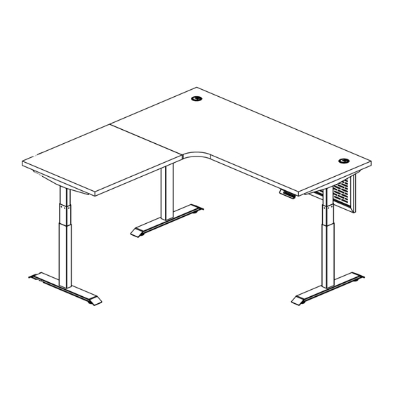
H-11113, H-11686
METRO COLLECTION –
ADJUSTABLE HEIGHT L-DESK
TOOLS NEEDED
Phillips
4 mm Allen Wrench
Screwdriver
(included)
10
5
4
11
5
4
3
NOTE: Count and inspect all pieces before
disposing of any carton or packing materials.
• Install bolts using 4 mm Allen wrench.
• Install screws using Phillips screwdriver.
CAUTION! Adjustable frame is heavy and
care should be used when moving it during
assembly.
PAGE 1 OF 24
1-800-295-5510
uline.com
Two Person Assembly
Recommended
1
6
7
8
3
9
PARTS
PARTS
#
DESCRIPTION
1
Desktop
2
Metal Modesty Panel
3
Foot with Leveling Glides
2
4
Lifting Column
5
Top Support Bracket
6
Center Frame
5
7
Control Box
8
Cable Management Tray
9
Programmable Handset
10
Return Top
4
11
Return Frame
3
A
Grommet
Cap x 2
D
M6 x 40 mm
Bolt x 12
G
ST5 x 16 mm
Screw x 2
J
Extension
Wire x 2
Para Español, vea páginas 9-16.
Pour le français, consulter les pages 17-24.
Hardware Kit
B
C
Modesty Panel
Modesty Panel
Bracket x 2
Connector x 2
E
F
M6 x 10 mm
M6 x 14 mm
Bolt x 30
Bolt x 48
H
I
ST3.5 x 16 mm
Cable
Screw x 10
Clip x 10
K
L
Power Cord x 1
Mounting
Plate x 2
1024 IH-11113
QTY.
1
1
3
3
3
1
1
1
1
1
1
Advertisement

Subscribe to Our Youtube Channel
Related Manuals for U-Line METRO H-11686


Summary of Contents for U-Line METRO H-11686
- Page 1 Para Español, vea páginas 9-16. Pour le français, consulter les pages 17-24. π H-11113, H-11686 1-800-295-5510 uline.com METRO COLLECTION – ADJUSTABLE HEIGHT L-DESK TOOLS NEEDED Phillips 4 mm Allen Wrench Two Person Assembly Screwdriver (included) Recommended PARTS PARTS DESCRIPTION QTY. Desktop Metal Modesty Panel Foot with Leveling Glides...
- Page 2 ASSEMBLY Place one lifting column (4) upside down on a 3. Attach foot with leveling glides (3) to lifting smooth, non-marring surface. Attach lifting column column (4) using four M6 x 40 mm bolts (D). Repeat to center frame (6) using four M6 x 10 mm bolts (E). on remaining lifting columns.
- Page 3 ASSEMBLY CONTINUED 5. Insert top support bracket (5) into the outside of With a second person, carefully place assembled return frame (11). Install using two M6 x 10 mm main desk frame on top of desktop (1). Adjust bolts (E). (See Figure 5) position of frame so that it aligns with corresponding holes in main desktop.
- Page 4 ASSEMBLY CONTINUED 9. Install eight M6 x 10 mm bolts (E) to tighten support 11. Connect the power cord (K), programmable bars in the return frame (11). (See Figure 9) handset (9) and lifting column cables to the control box (7). (See Figures 11-12) Figure 9 NOTE: Two of the pre-installed lifting column cables will not reach control box (7).
- Page 5 ASSEMBLY CONTINUED 12. Position loose cords underneath the cable 15. Align holes in the modesty panel brackets (B) and management tray (8) in center frame (6). Attach the connectors (C) with pre-threaded holes in the cable management tray to the center frame using desktop (1).
- Page 6 OPERATION Display Down Four Preset Setting Button Button Position Buttons Button Charger 2 3 4 1 2 3 4 M CAUTION! Ensure there are no obstacles in the desk's height adjustment path, and ensure the desk is not touching any walls. CAUTION! Ensure all cords are at the appropriate length to accommodate changes in height.
- Page 7 OPERATION CONTINUED LOCKING OPERATION • To lock the desk, press the "M" button to display " ". Hold the "M" button for 10 seconds until " " is displayed. • To unlock the desk, press and hold the "M" button for 10 seconds while " "...
- Page 8 TROUBLESHOOTING CONTINUED OPERATING ISSUE RECOMMENDATIONS Desk does not go up or down, but handset Faulty height limits may be programmed and displays digits that are flashing. should be canceled. Press the "M" setting button to display " " on the handset. Press and hold the "M"...
- Page 9 π H-11113, H-11686 800-295-5510 uline.mx ESCRITORIO EN L DE ALTURA AJUSTABLE – COLECCIÓN METROPOLITANA HERRMIENTAS NECESARIAS Desarmador Llave Allen de 4 mm Two Person Assembly de Cruz (incluida) Recommended PARTS PARTS DESCRIPTION QTY. Cubierta Recato de Metal Pata con Tapas Niveladoras Columna de Elevación Soporte Superior Armazón Cental...
- Page 10 ENSAMBLE Voltee una columna de elevación (4) y colóquela 3. Fije la pata con tapas niveladoras (3) a la columna sobre una superficie lisa que no deje marcas. Fije de elevación (4) utilizando cuatro tornillos la columna de elevación al armazón central (6) M6 x 40 mm (D).
- Page 11 CONTINUACIÓN DEL ENSAMBLE 5. Instale el soporte superior (5) en la parte exterior Con ayuda de otra persona, coloque el armazón del armazón del retorno (11). Instale utilizando dos ensamblado con cuidado encima de la cubierta (1). pernos M6 x 10 mm (E). (Vea Diagrama 5) Ajuste la posición del armazón de modo que se alinee con los orificios correspondientes de la cubierta.
- Page 12 CONTINUACIÓN DEL ENSAMBLE 9. Utilice ocho pernos M6 x 10 mm (E) para apretar las 11. Conecte el cable eléctrico (K), el control de barras de soporte en el armazón del retorno (11). programación (9) y los cables de las columnas (Vea Diagrama 9) de elevación a la caja de control (7).
- Page 13 CONTINUACIÓN DEL ENSAMBLE 12. Coloque los cables sueltos debajo de la bandeja 15. Alinee los orificios de los soportes del recato (B) y los para organizar cables (8) en el armazón central (6). conectores (C) con los orificios preperforados de la Instale la bandeja para organizar cables al armazón cubierta (1).
- Page 14 FUNCIONAMIENTO Pantalla Botón Botón Cuatro Botones de Botón de Cargador Arriba Abajo Posiciones Preprogramadas Ajuste 2 3 4 1 2 3 4 M ¡PRECAUCIÓN! Asegúrese de que no haya obstáculos en la trayectoria de la altura ajustable del escritorio y asegúrese de que no esté tocando ninguna pared. ¡PRECAUCIÓN! Asegúrese de que el largo de los cables se encuentre de tal manera que permita los cambios de altura.
- Page 15 CONTINUACIÓN DE FUNCIONAMIENTO OPERACIÓN DE BLOQUEO • Para bloquear el escritorio, presione el botón de ajuste "M" para mostrar "S-". Sostenga el botón "M" durante 10 segundos hasta que la pantalla muestre "LOC". • Para desbloquear el escritorio, presione y sostenga el botón "M" durante 10 segundos mientras la pantalla muestra "LOC".
- Page 16 CONTINUACIÓN DE SOLUCIÓN DE PROBLEMAS PROBLEMA DE FUNCIONAMIENTO RECOMENDACIONES El escritorio no sube ni baja, pero el control Los límites de altura podrían estar mal manual muestra dígitos que parpadean. programados y se deben cancelar. Presione el botón de ajuste "M" para mostrar "S-" en el control manual.
- Page 17 π H-11113, H-11686 1 800 295-5510 uline.ca COLLECTION METRO – BUREAU EN L À HAUTEUR RÉGLABLE OUTILS REQUIS Tournevis Clé Allen de 4 mm Montage à deux cruciforme (inclus) personnes recommandé PIÈCES PIÈCES DESCRIPTION QTÉ Surface de bureau Panneau cache-jambes en métal Pied avec patins de nivellement Colonne de levage Ferrure de support de la surface...
- Page 18 MONTAGE Placez une colonne de levage (4) à l'envers sur une 3. Fixez un pied avec patins de nivellement (3) à la surface lisse qui ne marque pas. Fixez la colonne colonne de levage (4) avec quatre boulons de levage au cadre central (6) avec quatre boulons M6 x 40 mm (D).
- Page 19 MONTAGE SUITE 5. Insérez une ferrure de support de la surface (5) dans 7. À deux, placez le cadre de bureau principal la partie extérieure du cadre de retour (11). Fixez-la assemblé avec soin sur la surface de bureau (1). avec deux boulons M6 x 10 mm (E).
- Page 20 MONTAGE SUITE 9. Installez huit boulons M6 x 10 mm (E) pour serrer les 11. Branchez le cordon d'alimentation (K), le contrôleur barres de support au cadre de retour (11). programmable (9) et les câbles de colonne de (Voir Figure 9) levage au boîtier de commande (7).
- Page 21 MONTAGE SUITE 12. Placez le surplus des cordons sous le plateau de 15. Alignez les trous des supports de panneau cache- gestion des câbles (8) dans le cadre central (6). jambes (B) et ceux des connecteurs (C) sur les trous Fixez le plateau de gestion des câbles au cadre filetés de la surface de bureau (1).
- Page 22 FONCTIONNEMENT Affichage Touche Touche Quatre touches de position Touche de Chargeur haut préréglée réglage 2 3 4 1 2 3 4 M MISE EN GARDE! Assurez-vous que le bureau ne touche aucun mur et qu'aucun obstacle n'entrave son mouvement. MISE EN GARDE! Assurez-vous que tous les cordons ont une longueur appropriée convenant au changement de hauteur.
- Page 23 FONCTIONNEMENT BLOCAGE DU FONCTIONNEMENT • Pour bloquer le bureau, appuyez sur la touche « M » pour afficher « ». Appuyez longuement sur la touche « M » pendant 10 secondes jusqu'à ce que « » s'affiche. • Pour débloquer le bureau, appuyez longuement sur la touche « M » pendant 10 secondes jusqu'à ce que « ...
- Page 24 DÉPANNAGE SUITE PROBLÈME RECOMMANDATIONS Le bureau ne monte ni ne descend, mais le Des limites de hauteur erronées peuvent être contrôleur affiche des chiffres qui clignotent. programmées et doivent être annulées. Appuyez sur la touche de réglage « M » pour afficher « ...
Need help?
Do you have a question about the METRO H-11686 and is the answer not in the manual?
Questions and answers