Advertisement
Quick Links
IT SERIES
I
ndustrial
AC Power Inverter
IT12-1400
IT12-2000
IT12-1600
IT12-2200S
IT12-1800
IT12-2400
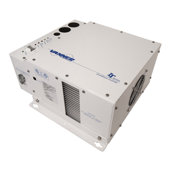
IT SERIES Industrial True Sine Wave Inverter
T
rue Sine Wave
Models
IT12-2600
IT12-2800
IT12-3000
Typical Installation
Owners Manual
IT12-3200
IT12-3600PL
IT24-3500
Owners Manual
1
Advertisement

Related Manuals for Vanner IT Series


Summary of Contents for Vanner IT Series
- Page 1 Owners Manual IT SERIES ndustrial rue Sine Wave AC Power Inverter Models IT12-1400 IT12-2000 IT12-2600 IT12-3200 IT12-1600 IT12-2200S IT12-2800 IT12-3600PL IT12-1800 IT12-2400 IT12-3000 IT24-3500 Typical Installation IT SERIES Industrial True Sine Wave Inverter Owners Manual...
- Page 2 IT SERIES Owner's Manual Alternator OEM Wire OEM Wire OEM Wire Charging Fuse 250 Amp Minimun Battery Common OEM Ground at Starter or Engine Block Charging Fuse 250 Amp Minimum Inverter Fuse See Figure 10 for Fuse and Wire Size...
- Page 3 (32.3) Auto Throttle Control (Volt Guard) Terminal 6 ................... 18 (32.5) Remote Low Battery Warning Terminal 8 .................... 19 (33) GFCI D ........................... 19 UPLEX ECEPTACLE (34) AC O ......................19 UTPUT IRING OMPARTMENT IT SERIES Industrial True Sine Wave Inverter Owners Manual...
- Page 4 ) ............18 IGURE HROTTLE ONTROL IAGRAM UARD EATURE ......................19 IGURE EMOTE ATTERY ARNING DC C ....................21 IGURE ABLE AND IZING HART UL L DC C ...................22 IGURE ISTED ERMINALS FOR ABLES IT SERIES Industrial True Sine Wave Inverter Owners Manual...
- Page 5 Introduction 1 INTRODUCTION Thank you for purchasing a Vanner IT SERIES Inverter. We are confident that you will be satisfied with its performance and its many features. With proper installation and care, you can look forward to years of service from this high performance product.
- Page 6 AC Output Voltage as needed to limit the AC Output Current. If the inverter reduces output voltage below 108 volts for 10 seconds, the inverter will shut itself OFF for Overload. IT SERIES Industrial True Sine Wave Inverter Owners Manual...
- Page 7 AC Output Voltage as needed to limit the AC Output Current. If the inverter reduces output voltage below 108 volts for 10 seconds, the inverter will shut itself OFF for Overload. ** At 77ºF(25ºC) the IT12-3600 can produce 3600 watts for at least 30 minutes before overheating. IT SERIES Industrial True Sine Wave Inverter Owners Manual...
- Page 8 ‘stand-by mode’ or ‘sleep mode’. While in the ‘Load Demand Mode’ 12-volt models consume approximately 0.5 amps of DC and 24-volt models consume approximately 0.25 amps of DC. IT SERIES Industrial True Sine Wave Inverter Owners Manual...
- Page 9 NEMA L5-20P plug. D07924 30 Amp AC Output Cord NEMA L5-30R receptacle (120 volt, 30 amp, twist- lock) receptacle on 1' long 10/3 SO cable with ring terminals. IT SERIES Industrial True Sine Wave Inverter Owners Manual...
- Page 10 4. To avoid the risk of fire, electrical shock, or injury to persons, do not use attachments not recommended or sold by the Vanner Power Group. 5. Vanner recommends that all AC and DC electrical wiring be performed by a licensed electrician or a qualified technician to ensure compliance with all applicable national and local wiring regulations.
- Page 11 5. NEVER smoke or allow a spark or flame near a battery. Gases produced by batteries are explosive. 6. Be careful when working with metal tools around batteries. Potentials exist for sparks or short-circuit of the battery or other electrical part which could cause an explosion. IT SERIES Industrial True Sine Wave Inverter Owners Manual...
- Page 12 4 COMPONENT IDENTIFICATION and DESCRIPTION of OPERATION Figure 3 Inverter Top View (1) Top entry for positive DC input cable (2) Top entry for negative DC input cable (3) Top entry for Remote Control Terminal Block IT SERIES Industrial True Sine Wave Inverter Owners Manual...
- Page 13 Feature will insure that the vehicle’s alternator operates at maximum output when needed. The Volt Guard circuit is designed to provide ‘ground control’ for a Bosch relay, Vanner part number 05235 or equal. Use the Bosch relay to operate the automatic throttle, Vanner 73-46 Automatic Throttle or equal.
- Page 14 (11) Bottom entry for positive DC input cable (12) Bottom entry for negative DC input cable (13) Positive DC Input Contact (14) Negative DC Input Contact (15) Bottom entry for Remote Control Terminal Block IT SERIES Industrial True Sine Wave Inverter Owners Manual...
- Page 15 (21) Side entry for AC output cable (24) Factory set-up jack (25) Air Exhaust Vents Figure 5 Inverter Front and Left Side View (26) Mounting Brackets ( 2 ) (27) Air Exhaust Vents IT SERIES Industrial True Sine Wave Inverter Owners Manual...
- Page 16 Provides ground control for a remote Low Battery Warning LOW DC Device. See item (32.5) & Fig 9. WARNING connection _____________________________________________ Terminal 7 and 9 Terminals 7 and 9 are NOT USED. IT SERIES Industrial True Sine Wave Inverter Owners Manual...
- Page 17 Component Identification and Description of Operation (32.1) Remote ON/OFF Switch Terminals 1, 2 and 3 The IT SERIES Inverter allows five styles of remote control wiring for customers who wish to supply and install a remote control switch or switches. Figure 7...
- Page 18 Use the Bosch relay to control the automatic throttle, Vanner 73-46 Automatic Throttle or equal. Install a ½ amp in-line fuse near the inverter as shown. The sketch below follows the 73-46 Automatic Throttle wiring instructions as for a Dynamic Inverter installation.
- Page 19 (See also item (5) Low Battery Warning Indicator Light (Low DC Warning) Terminal 8 is designed to provide ground control for a Bosch relay, Vanner part number 05235 or equal, to operate in conjunction with the Low DC Warning Indicator Light. Use the Bosch relay to operate an audible alarm, lights or other warning device.
- Page 20 6. If passing through steel or other ferrous metal walls, the DC input cables need to pass through the same hole to prevent causing a transformer effect. If two holes are required, cut a slot to connect the two holes to prevent heating of the ferrous metal. IT SERIES Industrial True Sine Wave Inverter Owners Manual...
- Page 21 (see figures 1,2,and 3). Two cable clamps and four plastic hole plugs are provided. Bolts are provided for connecting 5/16 diameter ring terminals to the DC Input Contacts. Optional compression lugs (Vanner part no. D08241) are available for cables sizes up to 250 MCM.
- Page 22 10. Verify that the inverter will turn ON but do not leave the inverter connected to the battery at this time (remove the fuse). Final battery connections will be made after all control and AC output installation issues have been inspected. IT SERIES Industrial True Sine Wave Inverter Owners Manual...
- Page 23 6. Refer to the description of operation of the indicator lights, Section 2, items 4 through10 to follow and verify correct inverter operation. 7. If the inverter is not operating as described, see Trouble Shooting Procedures IT SERIES Industrial True Sine Wave Inverter Owners Manual...
- Page 24 The following are the most common questions heard by Vanner service professionals. If your situation does not apply to the following categories, please contact your local Vanner Power Group Service Center or the Vanner Power Group Customer Service Department: 1-800-AC-POWER (1-800-227-6937). Please have your model and serial number available when consulting customer service.
- Page 25 Verify AC load specifications are not exceeded. Problem: Unit does not operate and a “burnt wire” smell emits from inverter. Check: Disconnect AC loads and battery immediately. Unit may require service, contact Vanner service department. IT SERIES Industrial True Sine Wave Inverter Owners Manual...
- Page 26 3. The product was purchased after January 1, 2000. Vanner does not warrant its products against any and all defects when: defect is a result of material or workmanship not provided by Vanner; normal wear and tear, or defects caused by misuse or use in contrary to instructions supplied, neglect, accident, reversed polarity, unauthorized repairs and/or replacements.
- Page 27 For maximum protection against electrical shock hazard, operate the Test Switch on the Ground Fault Circuit Interrupter at least once a month and record the values in this supplied table. Figure 12 GFCI Test Record YEAR 20___ IT SERIES Industrial True Sine Wave Inverter Owners Manual...
- Page 28 IT Series Owner's Manual Vanner Incorporated 4282 Reynolds Drive Hilliard, Ohio 43026 1-800-AC POWER (1-800-227-6937) Tel: 614-771-2718 Fax: 614-771-4904 www.vanner.com e-mail: pwrsales@vanner.com Owner's Manual Part Number D98494 Rev C August 30, 2022 Printed in USA IT SERIES Industrial True Sine Wave Inverter...
Need help?
Do you have a question about the IT Series and is the answer not in the manual?
Questions and answers